
Models:
80-200REOZJF
125/180REOZJG
230-275REOZJE
300-500REOZJ
350-500REOZJB
350-500REOZJC
350/400REOZJD
500REOZVC
550/600REOZVB
Controller:
APM603
Industrial Generator Set
TP-7100 2/21b
Operation

2 TP-7100 2/21
WARNING: This product can expose you to chemicals, including carbon monoxide and
benzene, which are known to the State of California to cause cancer and birth defects or
other reproductive harm. For more information go to www.P65warnings.ca.gov
WARNING: Breathing diesel engine exhaust exposes you to chemicals known to the
State of California to cause cancer and birth defects or other reproductive harm.
Always start and operate the engine in a well-ventilated area.
If in an enclosed area, vent the exhaust to the outside.
Do not modify or tamper with the exhaust system.
Do not idle the engine except as necessary.
For more information go to www.P65warnings.ca.gov/diesel
Product Identification Information
Product identification numbers determine service parts. Record the product identification numbers in the spaces below
immediately after unpacking the products so that the numbers are readily available for future reference. Record field-installed
kit numbers after installing the kits.
Generator Set Identification Numbers
Record the product identification numbers from the engine nameplate(s).
Model Designation _________________________________________________________
Specification Number _______________________________________________________
Serial Number: ____________________________________________________________
Controller Identification
Record the controller description from the generator set operation manual, spec sheet, or sales invoice.
Controller Description________________________________________________________
Engine Identification
Record the product identification information from the engine nameplate.
Manufacturer_________________________________________________________________
Model Designation___________________________________________________________
Serial Number_______________________________________________________________
Accessory Number
Accessory Description
Accessory Number
Accessory Description

TP-7100 2/21 3
Table of Contents
Safety Precautions and Instructions ........................................................................................................................................ 5
Introduction ................................................................................................................................................................................ 9
Service Assistance................................................................................................................................................................... 10
Section 1. Controller Specifications and Features ............................................................................................... 11
1.1 Introduction ............................................................................................................................................................ 11
1.2 Controller Specifications ......................................................................................................................................... 11
1.3 Controller Features................................................................................................................................................. 11
1.3.1 Switches and Controls ............................................................................................................................. 12
1.3.2 Annunciator LEDs .................................................................................................................................... 12
1.3.3 Touchscreen Display ............................................................................................................................... 13
1.3.4 Access Levels .......................................................................................................................................... 15
1.4 Touchscreen Calibration ........................................................................................................................................ 16
1.5 Using a Mouse with the APM603 Controller ........................................................................................................... 16
1.6 Inputs and Outputs ................................................................................................................................................. 17
1.7 Run Relay .............................................................................................................................................................. 17
Section 2. Operation ................................................................................................................................................ 19
2.1 Prestart Checklist ................................................................................................................................................... 19
2.2 Generator Set Operation ........................................................................................................................................ 20
2.2.1 Starting and Stopping Functions for a Single Generator Set.................................................................... 20
2.2.2 Start Signal .............................................................................................................................................. 20
2.2.3 Stop Signal............................................................................................................................................... 20
2.2.4 Engine Cooldown ..................................................................................................................................... 20
2.2.5 Emergency Stop ...................................................................................................................................... 21
2.2.6 Starting and Stopping Functions for a Generator Set in a Paralleled System .......................................... 22
2.3 Operation in Cold Weather Climates ...................................................................................................................... 23
2.4 Exercising the Generator Set ................................................................................................................................. 23
2.5 Warnings and Faults .............................................................................................................................................. 24
2.5.1 Yellow System Warning LED and Fault Messages .................................................................................. 24
2.5.2 Red System Fault Shutdown LED and Fault Messages .......................................................................... 24
2.5.3 Fault, Notice, and Status Displays ........................................................................................................... 24
2.5.4 Notifications (Bell icon) ............................................................................................................................ 25
2.6 Resetting the Controller (Following System Shutdown) ......................................................................................... 36
2.7 Controller Settings .................................................................................................................................................. 36
2.8 Screen Shots .......................................................................................................................................................... 38
2.9 Menu Navigation .................................................................................................................................................... 39
Section 3. Metering Menu and Screens ................................................................................................................. 41
3.1 Metering Screens ................................................................................................................................................... 41
3.1.1 Home ....................................................................................................................................................... 42
3.1.2 Customizing the Home Screens ............................................................................................................... 43
3.1.3 Favorites .................................................................................................................................................. 46
3.2 Electrical ................................................................................................................................................................. 48
3.2.1 Metering Screens, Electrical, Generator .................................................................................................. 48
3.2.2 Input Metering .......................................................................................................................................... 50
3.2.3 Output Metering ....................................................................................................................................... 52
3.2.4 Battery Charger ........................................................................................................................................ 54
3.3 Engine .................................................................................................................................................................... 56
3.4 Operation Records ................................................................................................................................................. 58
3.5 Load Management ................................................................................................................................................. 60
3.5.1 Metering, Load Management Overview Screen ....................................................................................... 61

4 TP-7100 2/21
3.5.2 Metering, Load Management, Status ....................................................................................................... 62
3.5.3 Load Management Setup Details ............................................................................................................. 67
Section 4. Setup Menus ........................................................................................................................................... 69
4.1 Setup Menus .......................................................................................................................................................... 69
4.1.1 Changing Settings .................................................................................................................................... 69
4.2 Electrical Setup ...................................................................................................................................................... 70
4.2.1 Generator Electrical Setup ....................................................................................................................... 70
4.2.2 Battery Charger Setup ............................................................................................................................. 71
4.2.3 Paralleling Setup ...................................................................................................................................... 72
4.3 Engine Setup .......................................................................................................................................................... 73
4.4 Setup, Communication Screen ............................................................................................................................... 75
4.5 Event Configuration ................................................................................................................................................ 77
4.5.1 Generator Set Information (Genset Info) .................................................................................................. 80
4.6 Data Log Screens................................................................................................................................................... 81
Section 5. Paralleling ............................................................................................................................................... 83
5.1 Introduction ............................................................................................................................................................ 83
5.2 Metering ................................................................................................................................................................. 84
5.2.1 Paralleling, Metering, Overview ............................................................................................................... 84
5.2.2 Paralleling, Metering Status ..................................................................................................................... 85
5.2.3 Paralleling, Metering, Details ................................................................................................................... 87
5.2.4 Paralleling, Metering, PGEN .................................................................................................................... 89
5.3 Setup ...................................................................................................................................................................... 90
5.3.1 Paralleling, Setup, PGEN ......................................................................................................................... 90
5.3.2 Paralleling, Setup, Protect Relay Screen ................................................................................................. 91
5.4 Generator Management ......................................................................................................................................... 93
5.4.1 Paralleling, Generator Management Status ............................................................................................. 95
5.4.2 Gen Management Modes......................................................................................................................... 96
5.4.3 Gen Management System Status, Generator .......................................................................................... 97
5.4.4 Paralleling, Gen Management, Setup Details .......................................................................................... 99
Section 6. Troubleshooting ................................................................................................................................... 101
6.1 Introduction .......................................................................................................................................................... 101
6.2 Generator Set and Controller ............................................................................................................................... 101
6.3 Engine .................................................................................................................................................................. 101
6.4 Transfer Switch .................................................................................................................................................... 101
6.5 General Troubleshooting Chart ............................................................................................................................ 102
6.6 Controller Display and Voltage Regulation Troubleshooting Chart ....................................................................... 106
Section 7. Accessories .......................................................................................................................................... 107
7.1 Battery Chargers .................................................................................................................................................. 107
7.2 Common Failure Relay ......................................................................................................................................... 108
7.3 Four-Input/Fifteen-Output Module ........................................................................................................................ 109
7.4 Manual Key Switch ............................................................................................................................................... 110
7.5 Remote Emergency Stop Kit ................................................................................................................................ 111
7.5.1 Remote emergency stop kit. .................................................................................................................. 111
7.5.2 Lockable Emergency Stop Switch .......................................................................................................... 111
7.6 Remote Serial Annunciator .................................................................................................................................. 113
7.7 Shunt Trip Line Circuit Breaker ............................................................................................................................ 115
Appendix A. Abbreviations ....................................................................................................................................... 117
Appendix B. Controller Displays from the Engine ECM ......................................................................................... 121
Appendix C. Alternator Protection ........................................................................................................................... 122
Appendix D. Operating Hour Service Log ............................................................................................................... 123

TP-7100 2/21 5
Safety Precautions and Instructions
IMPORTANT SAFETY INSTRUCTIONS. Electromechanical equipment, including generator sets, transfer switches, switchgear,
and accessories, can cause bodily harm and pose life-threatening danger when improperly installed, operated, or maintained.
To prevent accidents be aware of potential dangers and act safely. Read and follow all safety precautions and instructions.
SAVE THESE INSTRUCTIONS.
This manual has several types of safety precautions and instructions: Danger, Warning, Caution, and Notice.
DANGER
DANGER indicates a hazardous situation which, if not avoided, will result in death or serious injury.
WARNING
WARNING indicates a hazardous situation which, if not avoided, could result in death or serious injury.
CAUTION
CAUTION indicates a hazardous situation which, if not avoided, could result in minor or moderate injury.
NOTICE
NOTICE is used to address practices not related to physical injury.
Safety decals affixed to the equipment in prominent places alert the operator or service technician to potential hazards and
explain how to act safely. The decals are shown throughout this publication to improve operator recognition. Replace missing or
damaged decals.
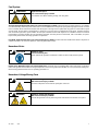
Accidental Starting
WARNING
Accidental starting.
Can cause severe injury or death.
Disconnect the battery cables before working on the generator set. Remove the
negative (–) lead first when disconnecting the battery. Reconnect the negative (–)
lead last when reconnecting the battery.
Disabling the generator set. Accidental starting can cause severe injury or death. Before working on the generator set or
equipment connected to the set, disable the generator set as follows: (1) Press the generator set off/reset button to shut down
the generator set. (2) Disconnect the power to the battery charger, if equipped. (3) Remove the battery cables, negative (–) lead
first. Reconnect the negative (–) lead last when reconnecting the battery. Follow these precautions to prevent the starting of the
generator set by the remote start/stop switch.
Note:
For Volvo units, Estop button must be pressed before disconnecting/reconnecting the batteries.
Battery
WARNING
Explosion.
Can cause severe injury or death.
Relays in the battery charger cause arcs or sparks.
Locate the battery in a well‐ventilated area. Isolate the battery charger from explosive
fumes.

6 TP-7100 2/21
Engine Backfire/Flash Fire
WARNING
Risk of fire.
Can cause severe injury or death.
Do not smoke or permit flames or sparks near fuels or the fuel system.
Combustible materials. A fire can cause severe injury or death. Generator set engine fuels and fuel vapors are flammable
and explosive. Handle these materials carefully to minimize the risk of fire or explosion. Equip the compartment or nearby area
with a fully charged fire extinguisher. Select a fire extinguisher rated ABC or BC for electrical fires or as recommended by the
local fire code or an authorized agency. Train all personnel on fire extinguisher operation and fire prevention procedures.
Exhaust System
WARNING
Carbon monoxide.
Can cause severe nausea, fainting, or death.
The exhaust system must be leakproof and routinely inspected.
Generator set operation. Carbon monoxide can cause severe nausea, fainting, or death. Carbon monoxide is an odorless,
colorless, tasteless, nonirritating gas that can cause death if inhaled for even a short time. Avoid breathing exhaust fumes when
working on or near the generator set. Never operate the generator set inside a building unless the exhaust gas is piped safely
outside. Never operate the generator set where exhaust gas could accumulate and seep back inside a potentially occupied
building.
Carbon monoxide symptoms. Carbon monoxide can cause severe nausea, fainting, or death. Carbon monoxide is a
poisonous gas present in exhaust gases. Carbon monoxide is an odorless, colorless, tasteless, nonirritating gas that can cause
death if inhaled for even a short time. Carbon monoxide poisoning symptoms include but are not limited to the following:
Light-headedness, dizziness
Physical fatigue, weakness in joints and muscles
Sleepiness, mental fatigue, inability to concentrate or speak clearly, blurred vision
Stomachache, vomiting, nausea
If experiencing any of these symptoms and carbon monoxide poisoning is possible, seek fresh air immediately and remain active.
Do not sit, lie down, or fall asleep. Alert others to the possibility of carbon monoxide poisoning. Seek medical attention if the
condition of affected persons does not improve within minutes of breathing fresh air.

TP-7100 2/21 7
Fuel System
WARNING
Explosive fuel vapors.
Can cause severe injury or death.
Use extreme care when handling, storing, and using fuels.
The fuel system. Explosive fuel vapors can cause severe injury or death. Vaporized fuels are highly explosive. Use extreme
care when handling and storing fuels. Store fuels in a well-ventilated area away from spark-producing equipment and out of the
reach of children. Never add fuel to the tank while the engine is running because spilled fuel may ignite on contact with hot parts
or from sparks. Do not smoke or permit flames or sparks to occur near sources of spilled fuel or fuel vapors. Keep the fuel lines
and connections tight and in good condition. Do not replace flexible fuel lines with rigid lines. Use flexible sections to avoid fuel
line breakage caused by vibration. Do not operate the generator set in the presence of fuel leaks, fuel accumulation, or sparks.
Repair fuel systems before resuming generator set operation.
Fuel tanks. Explosive fuel vapors can cause severe injury or death. Gasoline and other volatile fuels stored in day tanks or
subbase fuel tanks can cause an explosion. Store only diesel fuel in tanks.
Hazardous Noise
CAUTION
Hazardous noise.
Can cause hearing loss.
Never operate the generator set without a muffler or with a faulty exhaust system.
Engine noise. Hazardous noise can cause hearing loss. Generator sets not equipped with sound enclosures can produce
noise levels greater than 105 dBA. Prolonged exposure to noise levels greater than 85 dBA can cause permanent hearing loss.
Wear hearing protection when near an operating generator set.
Hazardous Voltage/Moving Parts
DANGER
Hazardous voltage.
Will cause severe injury or death.
Disconnect all power sources before opening the enclosure.
DANGER
Hazardous voltage. Moving parts.
Will cause severe injury or death.
Operate the generator set only when all guards and electrical enclosures are in place.

8 TP-7100 2/21
Hot Parts
WARNING
Hot engine and exhaust system.
Can cause severe injury or death.
Do not work on the generator set until it cools.

TP-7100 2/21 9
Introduction
This manual provides operation instructions for the diesel generator sets listed on the front cover when equipped with the
APM603 controller.
This manual contains generator set operation instructions for readers with user-level or operator-level access to the APM603
controller. Selected accessory information is also included.
Refer to the generator set maintenance manual and the engine operation manual for scheduled maintenance information.
Information in this publication represents data available at the time of print. Kohler Co. reserves the right to change this
publication and the products represented without notice and without any obligation or liability whatsoever.
Read this manual and carefully follow all procedures and safety precautions to ensure proper equipment operation and to avoid
bodily injury. Read and follow the Safety Precautions and Instructions section at the beginning of this manual. Keep this manual
with the equipment for future reference.
The equipment service requirements are very important for safe and efficient operation. Inspect the parts often and perform
required service at the prescribed intervals. Maintenance work must be performed by appropriately skilled and suitably trained
maintenance personnel familiar with generator set operation and service.
List of Related Materials
Separate literature contains installation and maintenance information not provided in this manual. Figure 1 lists the available
literature part numbers.
The engine electronic controls indicate engine fault codes in addition to the generator set controller. The engine operation and
service literature provide information for identifying engine fault codes. For the latest literature part numbers, see the generator
set parts catalog.
Literature Description
Literature Part No.
Generator Set Installation Manual
TP-5700
Generator Set Maintenance Manual
TP-7138
Generator Set/Controller Wiring Diagram Manual
80-300 kW (John Deere Units)
350-500 kW (John Deere Units)
500-600 kW (Volvo Units)
TP-6798
TP-6797
TP-6777
Communications Protocol Operation Manual
TP-7151
SiteTech
TM
Software Manual
TP-6701
Remote Serial Annunciator III (RSA III) Instructions
TT-1625
Figure 1 Related Literature
Abbreviations
This publication makes use of numerous abbreviations. Typically, the word(s) are spelled out along with the abbreviation in
parentheses when shown for the first time in a section. Appendix A, Abbreviations, also includes many abbreviation definitions.
SiteTech
TM
Software
A personal computer and Kohler SiteTech
TM
software may be required for programming the APM603 controller if the factory
default settings are not appropriate for the application. SiteTech software is also needed for assigning configurable inputs/outputs
and for updating the controller application code. Kohler SiteTech software is available only to Kohler-trained and authorized
distributors and dealers. Contact your local distributor/dealer for assistance.

10 TP-7100 2/21
Service Assistance
For professional advice and conscientious service, please
contact your nearest Kohler distributor or dealer.
Visit the Kohler Co. website at KOHLERPower.com.
Look at the labels and decals on your Kohler product
or review the appropriate literature or documents
included with the product.
Call toll free in the US and Canada 1-800-544-2444.
Outside the US and Canada, call the nearest
regional office.
Headquarters Europe, Middle East, Africa (EMEA)
Kohler EMEA Headquarters
Netherlands B.V.
Kristallaan 1
4761 ZC Zevenbergen
The Netherlands
Phone: (31) 168 331630
Fax: (31) 168 331631
Asia Pacific
Kohler Asia Pacific Headquarters
Singapore, Republic of Singapore
Phone: (65) 6264-6422
Fax: (65) 6264-6455
China
North China Regional Office, Beijing
Phone: (86) 10 6518 7950
(86) 10 6518 7951
(86) 10 6518 7952
Fax: (86) 10 6518 7955
East China Regional Office, Shanghai
Phone: (86) 21 6288 0500
Fax: (86) 21 6288 0550
India, Bangladesh, Sri Lanka
India Regional Office
Bangalore, India
Phone: (91) 80 3366208
(91) 80 3366231
Fax: (91) 80 3315972
Japan, Korea
North Asia Regional Office
Tokyo, Japan
Phone: (813) 3440-4515
Fax: (813) 3440-2727

TP-7100 2/21 11
Section 1. Controller Specifications and Features
1.1 Introduction
The specification sheet for each generator set provides model-specific generator and engine information. The controller
specification sheet provides specifications for this controller. Refer to the respective specification sheet for data not supplied in
this manual. Refer to the generator set service manual, installation manual, engine operation manual, and engine service manual
for additional specifications.
1.2 Controller Specifications
APM603 Controller
Power source with circuit protection
12 or 24VDC
Power draw
800 mAmps at 12VDC
400 mAmps at 24VDC
Humidity range
5-95% non-condensing
Operating temperature
-40° to 70°C (-40° to 158°F)
Storage temperature
-40° to 85°C (-40° to 185°F)
1.3 Controller Features
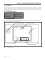
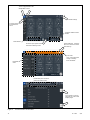
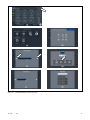
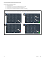
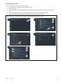
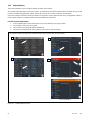
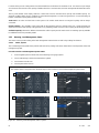
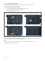
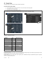
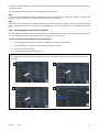
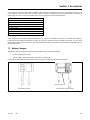
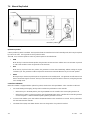
The controller features include the annunciator LED, touchscreen display, USB ports, switches and controls, and terminal blocks.
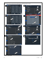
See Figure 2 for an illustration of the controller front panel.
Figure 2 APM603 Controller
Warning and shutdown LEDs
Touchscreen
Generator master control buttons:
OFF/RESET, AUTO, and RUN
Alarm Silence/Lamp Test button
USB ports (one USB and one mini-B)

12 TP-7100 2/21
Controller Features:
Large color touchscreen provides:
o Intuitive operation
o System status and metering displays
o Data logging and trending
o Event display and fault reset
Master control buttons with status LEDs
Fault LEDs:
o Yellow = Warning
o Red = Shutdown
Alarm horn and alarm silence button with LED
USB connector for downloading data files, uploading files, and data logging
Mini USB connector for controller setup using a PC with SiteTech
TM
software
The controller features, accessories, and menu displays depend upon the engine electronic control module (ECM) setup and
features.
1.3.1 Switches and Controls
Alarm Horn. The alarm horn alerts the operator or other attendants that a warning or shutdown condition exists.
Alarm (Horn) Silence. The alarm silence switch silences the alarm horn at the operator’s discretion. Press the master control
switch AUTO button before pressing the alarm silence button. The alarm horn cannot be silenced unless the master control
switch AUTO button is pressed.
Restore alarm horn switches at all locations, including those on remote annunciators, after correcting the fault condition and
resetting the controller. See Resetting the Controller in Section 2 for instructions to reset the controller.
Generator Set Master Control (OFF/RESET-AUTO-RUN). These buttons reset the controller fault LEDs and start/stop the
generator set. Additional information is shown in Section 2, Operation.
LED Test. Press and hold the Alarm Silence/Lamp Test button to test the controller indicator LEDs and fault LEDs.
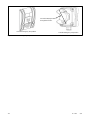
1.3.2 Annunciator LEDs
The controller has red and yellow annunciator fault LEDs that provide visual indication that a warning or shutdown is active. In
addition, each master control button has a status-indicating LED. See Figure 3.
LED/Button
LED Color
Description
Alarm (Fault) LED
Yellow (Warning) or
Red (Shutdown)
Yellow LED indicates a fault condition that does not shut down the generator set.
Correct all system warnings as soon as practical.
Red LED indicates that the generator set has shut down because of a fault condition.
The unit will not start until the condition is corrected and the controller is reset.
Off/Reset Button
Blue
Indicates the generator set is stopped.
Auto Button
Blue (System Ready)
Indicates the system is in standby mode and senses no faults. The unit is ready to start
by remote command.
Run Button
Blue
Indicates the generator set is cranking or running from a local command.
Alarm Silence Button
Orange
Indicates the alarm horn was silenced.
Figure 3 Annunciator LEDs

TP-7100 2/21 13
1.3.3 Touchscreen Display
The touchscreen display provides generator set and engine data, parameter settings, system status, and fault information. Some
values will display zero or N/A (not available) if the generator set is not running.
The main menus are listed below. Within each main menu are multiple submenus as described in Section 3.
Metering
Setup
Data Log
Paralleling (if enabled)
Active Events (Bell icon)
Controller Settings
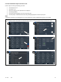
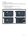
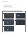
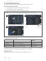
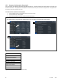
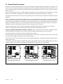
Figure 4 shows the important parts of the touchscreen.
Two tabs in the upper left corner allow the viewer to toggle between two independent screens.
The navigation menu on the left side of the screen can be expanded and contracted as shown.
The breadcrumb panel at the top identifies the current screen and the path.
The bell icon at the upper right indicates active alerts. Touch to view active events and event history.
The controller settings icon allows access to settings such as display brightness and date/time. This icon also contains
the link to the logon screen for the different access levels.
A scroll bar appears on the right side of the screen when there are multiple pages that can be viewed or accessed.
The boxes on the bottom of the Home screens allow the viewer to move between two screens.

14 TP-7100 2/21
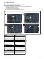
Figure 4 Screen Features and Functions
Expanded
menu
Touch to expand
and contract the
menu.
Touch to toggle between two
independent screens.
Touch the open square to move
to the other metering screen.
Breadcrumb panel shows the
path to the active screen.
Touch arrows to scroll up
and down on screens with
multiple pages.
Controller settings
Event notification. Touch the
bell icon to view active alerts
and event log.
Color Code:
Gray = No Active Faults
Orange = Warning
Red = Shutdown
Controller software version
number
Date and time

TP-7100 2/21 15
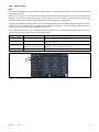
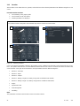
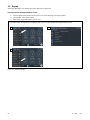
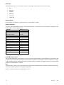
1.3.4 Access Levels
Note:
Have setup and adjustments of the controller performed only by an authorized Kohler distributor. The setup and adjustments
are password protected.
Different access levels are used to protect the controller from inadvertent changes that can adversely affect the generator set
operation. Access levels are described in Figure 5. The current access level is shown in the upper left corner of the screen
when the navigation menu is expanded as shown in Figure 6. The User level is the default level.
Some parameter settings are displayed at the user level but require operator access or higher to change the setting. Password-
controlled access is granted to trained, qualified Kohler distributors and dealers. See the Controller Settings Section for
instructions to log on at the Operator or Distributor access level.
After a set amount of time, the access automatically returns to the User level. The default session time duration is one hour.
The session time can be changed in the Controller Settings menu.
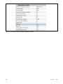
Access Level
Password
Description
User (0)
None
Can start and stop the generator set. Can navigate through the controller
menus and view, but not change, the settings..
Operator (1)
9879
Includes all User level functions, plus allows trained maintenance personnel to
adjust selected settings.
Technician (2)
Provided to Kohler trained and
authorized distributors and dealers.
Includes all Operator level functions, plus allows trained and authorized Kohler
distributors or dealers to adjust controller settings.
Factory (3)
Confidential
For factory use only.
Figure 5 Access Levels
Figure 6 Access Level Indication

16 TP-7100 2/21
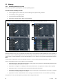
1.4 Touchscreen Calibration
Use your finger, the blunt end of a pen, or a stylus to navigate through the controller menus. Press or gently touch the words or
symbols on the screen as described in the procedures in this manual. Do not use a sharp instrument on the touchscreen; it may
damage the surface.
The touchscreen surface is calibrated at the factory. However, if touching an area on the screen seems to open the wrong menu,
or if there are other problems navigating the screen, it may be necessary to recalibrate the screen.
Procedure to Recalibrate the Touchscreen Display
1. Press and hold the ALARM SILENCE/LAMP TEST button for 5 seconds.
2. A window appears, asking “Do you want to recalibrate the touchscreen?” Touch Yes.
3. A spinning circle with a red dot in the center will appear on the screen. Carefully touch the center of the circle to define its
position on the screen. A small stylus may be more accurate than your finger for this operation. Do not use a sharp pencil or
other sharp tool.
4. Repeat step 3 for each circle that appears on the screen.
5. Touch Accept in the window that appears on the screen.
6. The controller will take a few minutes to reset. Wait for the Home screen to appear.
7. To check the touchscreen calibration, touch a few items on the screen, including items near the edges of the screen, to see
if the controller responds as expected. Repeat the calibration process, if necessary.
1.5 Using a Mouse with the APM603 Controller
A computer mouse can be used to navigate the menus, select parameters, and enter settings on the APM603 Controller. The
mouse can also be used to change controller settings such as date and time or to log on with a password.
Because of the large number of available mouse brands and styles, there is no guarantee that every mouse will work with the
controller.
A wired or wireless mouse can be used. Connect the mouse to the USB (type A) port on the front of the APM603 controller. See
the APM603 controller illustration on the previous page for the USB port location. A cursor appears on the controller’s display.
Use the mouse to move the cursor on the screen and click the left mouse button to select menus and parameters. Most of the
actions that can be performed by touching an item on the screen can also be accomplished using the mouse.
Note: A mouse and a flashdrive cannot be connected to the controller at the same. When a flash drive is needed for data logging,
taking screenshots, saving data files, or uploading files to the controller, the mouse must be disconnected.

TP-7100 2/21 17
1.6 Inputs and Outputs
The controller is equipped with the standard, dedicated inputs and outputs shown in Figure 7 and Figure 8. These onboard
inputs and outputs are factory set and cannot be adjusted.
Inputs
Input Type
Remote Engine Start
Two-Wire Input
Coolant Temperature, Degrees
Analog Input
Fuel Level, %
Auxiliary Fault (Shutdown)
Digital Input
Auxiliary Warning
Battery Charger Fault
Breaker Closed
Breaker Tripped
Excitation Overvoltage
Fuel Leak Alarm
Ground Fault Relay
Key Switch Auto
Key Switch Run
Low Fuel Level Switch
Remote Emergency Stop
Speed Bias
Analog Voltage Input,
Scalable up to +/- 10 VDC
Voltage Bias
Figure 7 Standard Dedicated User Inputs
Outputs
Output Type
Run
RDO1
Crank (John Deere models)
ECU Wakeup/Keyswitch (Volvo models)
RDO2
Horn
RDO3
Common Fault
RDO4
Reserved
RDO5
Reserved
RDO6
Close Breaker
RDO7
Trip Breaker
RDO8
Figure 8 Standard Dedicated User Outputs
An optional four-input, fifteen-output module is available. See the Accessories section for more information. A personal computer
and Kohler SiteTech™ software are required to assign input and output functions to the inputs and outputs on the I/O modules.
SiteTech is available to Kohler authorized distributors and dealers.
1.7 Run Relay
The run relay is provided as standard equipment with the APM603 controller. The run relay kit energizes only when the generator
set runs. Use the run relay kit to control air intake and radiator louvers, alarms, and/or other signaling devices. Refer to the
generator set Installation Manual and the generator set wiring diagrams for connections.

18 TP-7100 2/21

TP-7100 2/21 19
Section 2. Operation
2.1 Prestart Checklist
To ensure continued satisfactory operation, perform the following checks or inspections before or at each startup, as designated,
and at the intervals specified in the service schedule. In addition, some checks require verification after the unit starts.
DANGER
Hazardous voltage. Moving parts.
Will cause severe injury or death.
Operate the generator set only when all guards and electrical enclosures are in place.
Note:
Use the procedures in this document after the generator set has been installed according to the instructions in the generator set
Installation Manual.
Air Cleaner. Check for a clean and installed air cleaner element to prevent unfiltered air from entering engine.
Air Inlets. Check for clean and unobstructed air inlets.
Battery. Check for tight battery connections. Consult the battery manufacturer’s instructions regarding battery care and maintenance.
Coolant Level. Check the coolant level according to the cooling system maintenance information.
Note: Block Heater Damage.
The block heater will fail if the energized heater element is not immersed in coolant. Fill the cooling system before turning on the block
heater. Run the engine until it is warm, and refill the radiator to purge the air from the system before energizing the block heater.
Diesel Exhaust Fluid (DEF) Tank, if equipped. Ensure that there is an adequate DEF supply; keep the DEF tank full. When filling, watch
that the DEF tank is not overfilled.
Drive Belts. Check the belt condition and tension of the radiator fan, water pump, and battery charging alternator belt(s) according to the
drive belt system maintenance information.
Enclosure Doors, if equipped. Check that the service access doors are closed and secured. Leaving the doors open will create
excessive noise. Check that the enclosure door to the load connection panel is closed and secured. Some units have a micro switch
safety feature that will trip (by shunt trip) the main line circuit breaker if the load connection panel is open.
Exhaust System. Check for exhaust leaks and blockages. Check the silencer and piping condition and check for tight exhaust system
connections.
Inspect the exhaust system components (exhaust manifold, exhaust line, flexible exhaust, clamps, silencer, and outlet pipe) for
cracks, leaks, and corrosion.
Check for corroded or broken metal parts and replace them as needed.
Check for loose, corroded, or missing clamps and hangers. Tighten or replace the exhaust clamps and/or hangers as needed.
Check that the exhaust outlet is unobstructed.
Visually inspect for exhaust leaks (blowby). Check for carbon or soot residue on exhaust components. Carbon and soot residue
indicates an exhaust leak. Seal leaks as needed.
Fuel Level. Check the fuel level and keep the tank(s) full to ensure adequate fuel supply. (diesel models)
Lamp Test. Press the lamp-test button to verify all controller LEDs are operational.
Oil Level. Check the oil level. Maintain the oil level at or near, not over, the full mark on the dipstick.
Operating Area. Check for obstructions that could block the flow of cooling air. Keep the air intake area clean. Do not leave rags, tools, or
debris on or near the generator set.
Radiator. Check that the radiator fins and air inlets/outlets are clean of leaves, insects, dirt, and other debris. Use compressed air to clear
the obstructed passages as needed.
Visual Inspection. Walk around the generator set and look for leaking fluids, loose or dangling wiring, and loose or missing hardware.
Repair as needed before starting the generator set. Repeat the visual inspection routinely while the unit is running.

20 TP-7100 2/21
2.2 Generator Set Operation
The controller allows operation of the generator set as detailed below.
2.2.1 Starting and Stopping Functions for a Single Generator Set
There are three primary modes of operation, selected by pressing the controller buttons.
Button
Description
OFF/RESET
Press the OFF/RESET button to stop the generator set immediately, with no engine cooldown.
The generator set remains off and will not respond to a remote start signal.
Press and HOLD the OFF/RESET button for 3 seconds to reset an active fault (shutdown). Be
sure to identify and correct the problem that caused the shutdown before clearing the fault.
AUTO
Press AUTO to place the generator set into automatic (standby) mode. The generator set will
respond to remote start and remote stop signals.
RUN
Press the RUN button to start the generator set. The generator set runs until the OFF/RESET or
AUTO button is pressed or until a fault condition causes the generator set to shut down.
Figure 9 Controller Button Operation
Notes:
The alarm horn sounds and the Not-In-Auto Warning display appears whenever the generator set is not in the AUTO
mode.
The transient start/stop function of the controller prevents accidental cranking of the rotating engine. The generator set
stops and recranks when the OFF/RESET button is momentarily pressed and then the RUN button is pressed.
The controller provides up to 30 seconds of programmable cyclic cranking and up to 60 seconds rest with up to 6
cycles. The default setting is 15 seconds cranking and 15 seconds rest for 3 cycles. An authorized Kohler distributor or
dealer can make cyclic cranking adjustments using SiteTech
TM
software.
2.2.2 Start Signal
When the generator set is in AUTO mode, it can respond to a start signal. A start signal can include any of the following:
A remote start signal via contacts 3 and 4 (closing a contact between 3 and 4 on terminal block TB-12), typically
received from an automatic transfer switch (ATS) or a remote panel. A closed contact across 3 and 4 takes precedence
over all other start signals. If the generator set is already running, it will keep running and the original source of that
start signal will be ignored.
System Start (AUTO-START). Press AUTO and RUN simultaneously to send a start signal.
Communications-based start command from SiteTech
TM
or a Modbus-based remote panel.
2.2.3 Stop Signal
A stop signal can include any of the following:
Removal of start signal via contacts 3 and 4 (opening the contact between 3 and 4).
System Stop (AUTO-OFF). Press AUTO and OFF simultaneously on any controller in the system to send a stop
signal to cancel the system start.
Note:
Pressing AUTO and OFF simultaneously has no effect if the system start is not active or if the system is receiving a
start signal from another source.
Communications-based stop command from SiteTech
TM
or a Modbus-based remote panel.
2.2.4 Engine Cooldown
The engine cooldown cycle runs the generator set with no load to allow hot engine components time to cool slowly before the
engine is stopped.
When the generator set is running in AUTO mode, an engine cooldown cycle begins when the remote start input is deactivated
or a stop signal is received.
Page is loading ...
Page is loading ...
Page is loading ...
Page is loading ...
Page is loading ...
Page is loading ...
Page is loading ...
Page is loading ...
Page is loading ...
Page is loading ...
Page is loading ...
Page is loading ...
Page is loading ...
Page is loading ...
Page is loading ...
Page is loading ...
Page is loading ...
Page is loading ...
Page is loading ...
Page is loading ...
Page is loading ...
Page is loading ...
Page is loading ...
Page is loading ...
Page is loading ...
Page is loading ...
Page is loading ...
Page is loading ...
Page is loading ...
Page is loading ...
Page is loading ...
Page is loading ...
Page is loading ...
Page is loading ...
Page is loading ...
Page is loading ...
Page is loading ...
Page is loading ...
Page is loading ...
Page is loading ...
Page is loading ...
Page is loading ...
Page is loading ...
Page is loading ...
Page is loading ...
Page is loading ...
Page is loading ...
Page is loading ...
Page is loading ...
Page is loading ...
Page is loading ...
Page is loading ...
Page is loading ...
Page is loading ...
Page is loading ...
Page is loading ...
Page is loading ...
Page is loading ...
Page is loading ...
Page is loading ...
Page is loading ...
Page is loading ...
Page is loading ...
Page is loading ...
Page is loading ...
Page is loading ...
Page is loading ...
Page is loading ...
Page is loading ...
Page is loading ...
Page is loading ...
Page is loading ...
Page is loading ...
Page is loading ...
Page is loading ...
Page is loading ...
Page is loading ...
Page is loading ...
Page is loading ...
Page is loading ...
Page is loading ...
Page is loading ...
Page is loading ...
Page is loading ...
Page is loading ...
Page is loading ...
Page is loading ...
Page is loading ...
Page is loading ...
Page is loading ...
Page is loading ...
Page is loading ...
Page is loading ...
Page is loading ...
Page is loading ...
Page is loading ...
Page is loading ...
Page is loading ...
Page is loading ...
Page is loading ...
Page is loading ...
Page is loading ...
Page is loading ...
Page is loading ...
Page is loading ...
Page is loading ...
Page is loading ...
Page is loading ...
-
 1
1
-
 2
2
-
 3
3
-
 4
4
-
 5
5
-
 6
6
-
 7
7
-
 8
8
-
 9
9
-
 10
10
-
 11
11
-
 12
12
-
 13
13
-
 14
14
-
 15
15
-
 16
16
-
 17
17
-
 18
18
-
 19
19
-
 20
20
-
 21
21
-
 22
22
-
 23
23
-
 24
24
-
 25
25
-
 26
26
-
 27
27
-
 28
28
-
 29
29
-
 30
30
-
 31
31
-
 32
32
-
 33
33
-
 34
34
-
 35
35
-
 36
36
-
 37
37
-
 38
38
-
 39
39
-
 40
40
-
 41
41
-
 42
42
-
 43
43
-
 44
44
-
 45
45
-
 46
46
-
 47
47
-
 48
48
-
 49
49
-
 50
50
-
 51
51
-
 52
52
-
 53
53
-
 54
54
-
 55
55
-
 56
56
-
 57
57
-
 58
58
-
 59
59
-
 60
60
-
 61
61
-
 62
62
-
 63
63
-
 64
64
-
 65
65
-
 66
66
-
 67
67
-
 68
68
-
 69
69
-
 70
70
-
 71
71
-
 72
72
-
 73
73
-
 74
74
-
 75
75
-
 76
76
-
 77
77
-
 78
78
-
 79
79
-
 80
80
-
 81
81
-
 82
82
-
 83
83
-
 84
84
-
 85
85
-
 86
86
-
 87
87
-
 88
88
-
 89
89
-
 90
90
-
 91
91
-
 92
92
-
 93
93
-
 94
94
-
 95
95
-
 96
96
-
 97
97
-
 98
98
-
 99
99
-
 100
100
-
 101
101
-
 102
102
-
 103
103
-
 104
104
-
 105
105
-
 106
106
-
 107
107
-
 108
108
-
 109
109
-
 110
110
-
 111
111
-
 112
112
-
 113
113
-
 114
114
-
 115
115
-
 116
116
-
 117
117
-
 118
118
-
 119
119
-
 120
120
-
 121
121
-
 122
122
-
 123
123
-
 124
124
-
 125
125
-
 126
126
-
 127
127
-
 128
128


Ask a question and I''ll find the answer in the document
Finding information in a document is now easier with AI
Related papers
-
Kohler 300REZXD Operating instructions
-
Kohler KD1250-4 Operating instructions
-
Kohler Generator Sets 20--2800 kW User manual
-
-
-
Kohler KG60 Operating instructions
-
-
-
-
Other documents
-
Rubbermaid 2032729 User guide
-
Rubbermaid 1812251 User manual
-
 tio 230V User manual
-
Generac 6873 Operating instructions
-
Smartgen HSC941 Owner's manual
-
 Active Thermal Management 00-301-03 Datasheet
-
 Ista AMF2.0 User manual
-
Alpha AlphaGen Curbside Owner's manual
-
Marathon GPN017 Owner's manual
-
Planet 1-Bay User manual


