KitchenAid KUBL314KSS Operating instructions
- Type
- Operating instructions

W11530526
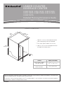
Panel ready models
(with 3/4” panel)
Stainless and
black stainless
23
13
/16” (60.7 cm)
23
5
/8” (60.2 cm)
Variant Depth (no handle)
*
Add 5/8” (1.6 cm) to the height dimension
when leveling legs are fully extended.
**
For custom panel models, this will vary.
†
Add 1/4” (6.4 mm) to the height dimension
for height with hinge covers.
Product Dimensions
1
Depth
(no handle)
23
7
/8”
(60.72 cm)
34
3
/8”
(87.32 cm)
*
†
30
5
/8”
(77.75 cm)
**
3
9
/16”
(9 cm)
*
Because Whirlpool Corporation policy includes a continuous commitment to improve our products, we reserve the
right to change materials and specifications without notice.
Dimensions are for planning purposes only. For complete details, see Installation Instructions packed with product.
Specifications subject to change without notice.
UNDER COUNTER
BEVERAGE CENTER
KUBR314KSS, KUBL314KSS, KUBR314KBS,
KUBL314KBS, KUBR214KSB, KUBL214KSB,
KUBR214KPA
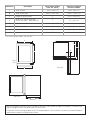
Detailed Planning Dimensions Guide

Dimension Description
Panel ready models
(with 3/4” panel)
Stainless and black
stainless models
A
Width of door
B
Width of the grille
C Height to top of handle
D
Width from side of beverage
center to handle - door open 90°
E Depth without door
F Depth with door
G Depth with handle
H
23
3
/4” (60.3 cm) 23
3
/4” (60.3 cm)
23
13
/16” (60.5 cm) 23
13
/16” (60.5 cm)
**
31
1
/8” (78.85 cm)
**
2
1
/3” (5.95 cm)
21
11
/16” (55.1 cm) 21
11
/16” (55.1 cm)
23
13
/16” (60.7 cm)
23
5
/8” (60.2 cm)
**
26
7
/16” (67.15 cm)
47
15
/16” (121.8 cm) 47
15
/16” (121.8 cm)
Depth with door open 90°
**
For custom panel models, this will vary.
2
Front
view
A
C
B
Side view
22
3
/8”
(56.8 cm)
Because Whirlpool Corporation policy includes a continuous commitment to improve our products, we reserve the
right to change materials and specifications without notice.
Dimensions are for planning purposes only. For complete details, see Installation Instructions packed with product.
Specifications subject to change without notice.
E
F
G
D
H
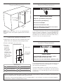
Top view

C
A
F
A
F
E
B
D
Back wall
Recessed
receptacle
locations
Lighter grey area indicates recommended necessed
power outlet (located behind the beverage center).
Power cord length is 60” (152.4 cm).
For fl ush
installation,
the power
outlet can
be installed
in adjacent
cabinetry with
a cutout on the
power cord
side for routing
of the power
cord.
A
B
C
3” (7.55 cm)
4
1
/2” (11.37 cm)
9
1
/4” (23.47 cm)
Electrical Supply Location
Electrical Requirements
A 115 V, 60 Hz, AC only, 15 A or 20 A fused, grounded
electrical supply is required. It is recommended that a
separate circuit serving only your beverage center be
provided. Use an outlet that cannot be turned off by a
switch. Do not use an extension cord.
Electrical Shock Hazard
Plug into a grounded 3 prong outlet.
Do not remove ground prong.
Do not use an adapter.
Do not use an extension cord.
Failure to follow these instructions can result in
death, fire, or electrical shock.
Dimensions
For the beverage center to be fl ush with the front of the
base cabinets, remove any baseboards or moldings
from the rear of the opening.
Flooring under product must be at the same level as
the room. If the fl oor of the opening is not level with the
kitchen fl oor, shim the opening to make it level with the
kitchen fl oor.
Location Requirements
Explosion Hazard
Keep flammable materials and vapors, such as
gasoline, away from beverage center.
Failure to do so can result in death, explosion, or fire.
3
Because Whirlpool Corporation policy includes a continuous commitment to improve our products, we reserve the
right to change materials and specifications without notice.
Dimensions are for planning purposes only. For complete details, see Installation Instructions packed with product.
Specifications subject to change without notice.
NOTE: Make sure there is 3” (7,6 cm) space between
beverage center and adjacent appliance/wall for door
swing.
Opening Dimensions
12
1
/16” (30.64 cm)
21
3
/4” (55.16 cm)
1
3
/4” (4.44 cm)
D
E
F
34
1
/2” (87.6 cm)
min
35” (88.9 cm)
max
.
24”
(60.96 cm)
min
24”
(60.96 cm)
min

IMPORTANT:
The graphics in following sections show a custom
panel for a door with the hinges installed on the right-
hand side. If your beverage center has the hinges
installed on the left-hand side, rotate the custom
frame 180° so the hinge markings will be on the left.
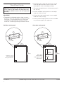
Wood Panel Guide
CAUTION: Installation of door panels with less than
a 3/8” (0.95 cm) gap between the door panel and
the adjacent cabinet increases the risk of potential
pinching.
Glass door overlay panel
Glass door
overlay panel
and hinge routing
dimensions.
4
Solid door overlay panel
Solid door overlay
panel and hinge
routing dimensions.
2"
(53 mm)
1/4"
(7 mm)
1/8"
(3 mm)
1/2"
(12 mm)
4
15
/16”
(125 mm)
23
3
/4”
(60.3 cm)
30
5
/8”
(77.75 cm)
2"
(53 mm)
1/4"
(7 mm)
1/8"
(3 mm)
1/2"
(12 mm)
4
15
/16”
(125 mm)
23
3
/4”
(60.3 cm)
17
1
/16”
(43.3 cm)
21
13
/16”
(55.4 cm)
30
5
/8”
(77.75 cm)
Panel dimensions shown are the minimum size to
cover the appliance door. Panels can be made
taller/wider to match surrounding cabinetry.
The recommended thickness of the overlay panel is
3/4” (19 mm).
Custom solid door overlay panel must not weigh
more than 20 lb (9.07 kg).
Custom glass door overlay panel must not weigh
more than 10 lb (4.54 kg).
Overlay panels weighing more than recommended
may cause damage to your appliance.
W11530526 12/2020
®
/™ ©2020 All rights reserved. Used under license in Canada.
-
 1
1
-
 2
2
-
 3
3
-
 4
4


KitchenAid KUBL314KSS Operating instructions
- Type
- Operating instructions
Ask a question and I''ll find the answer in the document
Finding information in a document is now easier with AI
Related papers
Other documents
-
JennAir JUBFR242HL User guide
-
JennAir JUWFL242HM User guide
-
Jenn-Air JUGFL242HM00 Owner's manual
-
-
-
-
-
JennAir JDTSS246GM Specification
-
-