MicroNet TMR
®
5009
Digital Control System
Volume 2
Installation/Hardware Manual
Manual 85580V2 (Revision E)

WARNING—DANGER OF DEATH OR PERSONAL INJURY
WARNING—FOLLOW INSTRUCTIONS
Read this entire manual and all other publications pertaining to the work to be performed
before installing, operating, or servicing this equipment. Practice all plant and safety
instructions and precautions. Failure to follow instructions can cause personal injury and/or
property damage.
WARNING—OUT-OF-DATE PUBLICATION
This publication may have been revised or updated since this copy was produced. To verify
that you have the latest revision, be sure to check the Woodward website:
www.woodward.com/pubs/current.pdf
The revision level is shown at the bottom of the front cover after the publication number. The
latest version of most publications is available at:
www.woodward.com/publications
If your publication is not there, please contact your customer service representative to get
the latest copy.
WARNING—OVERSPEED PROTECTION
The engine, turbine, or other type of prime mover should be equipped with an overspeed
shutdown device to protect against runaway or damage to the prime mover with possible
personal injury, loss of life, or property damage.
The overspeed shutdown device must be totally independent of the prime mover control
system. An overtemperature or overpressure shutdown device may also be needed for
safety, as appropriate.
WARNING—PROPER USE
Any unauthorized modifications to or use of this equipment outside its specified
mechanical, electrical, or other operating limits may cause personal injury and/or property
damage, including damage to the equipment. Any such unauthorized modifications: (i)
constitute "misuse" and/or "negligence" within the meaning of the product warranty
thereby excluding warranty coverage for any resulting damage, and (ii) invalidate product
certifications or listings.
CAUTION—POSSIBLE DAMAGE TO EQUIPMENT OR PROPERTY
CAUTION—BATTERY CHARGING
To prevent damage to a control system that uses an alternator or battery-charging device, make
sure the charging device is turned off before disconnecting the battery from the system.
CAUTION—ELECTROSTATIC DISCHARGE
Electronic controls contain static-sensitive parts. Observe the following precautions to
prevent damage to these parts.
• Discharge body static before handling the control (with power to the control turned off,
contact a grounded surface and maintain contact while handling the control).
• Avoid all plastic, vinyl, and Styrofoam (except antistatic versions) around printed circuit
boards.
• Do not touch the components or conductors on a printed circuit board with your hands
or with conductive devices.
IMPORTANT DEFINITIONS
• A WARNING indicates a potentially hazardous situation which, if not avoided, could result in
death or serious injury.
•
A CAUTION indicates a potentially hazardous situation which, if not avoided, could result in
damage to equipment or property.
•
A NOTE provides other helpful information that does not fall under the warning or caution
categories.
Revisions—Text changes are indicated by a black line alongside the text.
Woodward Governor Company reserves the right to update any portion of this publication at any time. Information
provided by Woodward Governor Company is believed to be correct and reliable. However, no responsibility is
assumed by Woodward Governor Company unless otherwise expressly undertaken.
© Woodward 1997
All Rights Reserved

Manual 85580V2 5009 Installation/Hardware
Woodward i
Contents
REGULATORY COMPLIANCE........................................................................ IV
ELECTROSTATIC DISCHARGE AWARENESS ..................................................V
CHAPTER 1. GENERAL INFORMATION...........................................................1
CHAPTER 2. HARDWARE DESCRIPTION........................................................2
Introduction.............................................................................................................2
Main Control Chassis .............................................................................................2
System Power Supplies .........................................................................................3
Module Descriptions...............................................................................................4
Cabinet (optional) .................................................................................................13
OpView™ Operator Interface (optional)...............................................................13
CHAPTER 3. MECHANICAL INSTALLATION...................................................14
Storage .................................................................................................................14
Unpacking.............................................................................................................14
Unit Location.........................................................................................................16
Install Cabinet (If included)...................................................................................16
Install 5009 Control and Power Chassis ..............................................................18
Install Modules......................................................................................................19
Install Analog Termination Modules .....................................................................24
Install Discrete Field Termination Modules ..........................................................26
Install OpView™ Interface (if included) ................................................................29
CHAPTER 4. ELECTRICAL INSTALLATION....................................................31
Introduction...........................................................................................................31
Cabinet (if included)..............................................................................................31
System Cables (if cabinet is not included) ...........................................................31
Shields and Grounding.........................................................................................32
Input Power ..........................................................................................................33
Speed Sensor Inputs............................................................................................35
Analog Inputs........................................................................................................39
Analog Outputs.....................................................................................................41
Actuator Outputs...................................................................................................41
DTM Contact Inputs (F/T Relay–Discrete In) .......................................................43
DTM Relay Outputs (F/T Relay Outputs) .............................................................46
Serial Communications ........................................................................................53
Printer ...................................................................................................................56
OpView .................................................................................................................56
Control Wiring Diagrams ......................................................................................57
System Power-Up.................................................................................................69
CHAPTER 5. TROUBLESHOOTING AND MODULE REPLACEMENT..................70
Introduction...........................................................................................................70
Main Power Supply...............................................................................................70
Kernel Power Supply (A1) ....................................................................................72
CPU Module .........................................................................................................73
Analog and Discrete I/O Modules.........................................................................74
Serial Input/Output (SIO) Module .........................................................................75
Termination Modules............................................................................................76
Diagnostics ...........................................................................................................78
System Troubleshooting Guide ............................................................................79
CHAPTER 6. HARDWARE SPECIFICATIONS..................................................86

5009 Installation/Hardware Manual 85580V2
ii Woodward
Contents
CHAPTER 7. SYSTEM MAINTENANCE ..........................................................92
Cables and Connections ......................................................................................92
Fans......................................................................................................................92
Air Filter Maintenance...........................................................................................92
Battery Check .......................................................................................................92
CHAPTER 8. MICRONET TMR
®
COMPATIBLE PRODUCTS ............................93
Operator Control Panel (OCP) .............................................................................94
DSLC™ Digital Synchronizer & Load Control ......................................................96
Real Power Sensor (RPS)....................................................................................98
CHAPTER 9. SERVICE OPTIONS................................................................102
Product Service Options.................................................................................... 102
Returning Equipment for Repair........................................................................ 103
Replacement Parts ............................................................................................ 104
How to Contact Woodward................................................................................ 104
Engineering Services......................................................................................... 105
Technical Assistance......................................................................................... 106
DECLARATIONS .......................................................................................108
Illustrations and Tables
Figure 2-1. Control and Power Chassis .................................................................3
Figure 2-2. Kernel Power Supply Block Diagram...................................................5
Figure 2-3. CPU Module.........................................................................................6
Figure 2-4. CPU Communications Port Filter Kit Installation Instructions..............7
Figure 2-5. MPU and Analog I/O Module ...............................................................8
Figure 2-6. Analog Termination Module Diagram ..................................................9
Figure 2-7. Discrete Input/Output Module ............................................................10
Figure 2-8. DTM Block Diagram...........................................................................12
Figure 2-9. SIO Module Block Diagram................................................................13
Figure 3-1. Hardware Identification ......................................................................15
Figure 3-2. Cabinet Dimensions...........................................................................17
Figure 3-3. Chassis-to-Chassis Power Cable W1-B ............................................18
Figure 3-4a. Outline Drawing of 5009 Main Chassis............................................20
Figure 3-4b. Outline Drawing of 5009 Main Chassis............................................21
Figure 3-4c. Outline Drawing of 5009 Power Chassis .........................................22
Figure 3-5. Outline Diagram of Module with Label...............................................23
Figure 3-6. Module Location Diagram ..................................................................23
Figure 3-7. DIN Rail & ATM Outline Drawing.......................................................25
Figure 3-8. ATM Grounding Diagram ...................................................................26
Figure 3-9. DTM Outline Drawing.........................................................................27
Figure 3-10. DTM Mounting Configuration ...........................................................28
Figure 3-11. OpView Outline Drawing..................................................................29
Figure 3-12. Mounting Template ..........................................................................30
Figure 4-1. Shield Termination Diagram ..............................................................33
Figure 4-2. Example MPU Interface Wiring Diagram ...........................................36
Figure 4-3a. Example 24 V Proximity Probe Wiring Diagram ..............................37
Figure 4-3b. Example 12 V Proximity Wiring Diagram.........................................37
Figure 4-4. Example Analog Input Wiring Diagrams ............................................40

Manual 85580V2 5009 Installation/Hardware
Woodward iii
Illustrations and Tables
Figure 4-5. Example Analog Output Wiring Diagram...........................................41
Figure 4-6. Example Single Coil Actuator Wiring Diagram ..................................42
Figure 4-7. Example Dual Coil Actuator Wiring Diagram.....................................43
Figure 4-8. Optional Internal 24Vdc Contact Wetting Configuration ....................44
Figure 4-9. Optional External Contact Wetting Configurations ............................45
Figure 4-10. Latent Fault Detection Verification Graph—18–32 Vdc Circuitry ....48
Figure 4-11. Latent Fault Detection Verification Graph—88–132 Vac Circuitry ..49
Figure 4-12. Latent Fault Detection Verification Graph—100–150 Vdc Circuitry 49
Figure 4-13. Jumper and Relay Location Diagram ..............................................51
Figure 4-14. DTM Labels......................................................................................52
Figure 4-15. Example Relay Output Wiring Diagram...........................................53
Figure 4-16. CPU Communications Port..............................................................55
Figure 4-17. Typical Communications Cable Connections ..................................55
Figure 4-18a. Cabinet—Device Location Diagram ..............................................58
Figure 4-18b. Cabinet—Device Location Diagram ..............................................59
Figure 4-19. System Cable Layout Diagram ........................................................60
Figure 4-20. Power Supply Wiring Diagram.........................................................61
Figure 4-21. ATM–1 Wiring Diagram ...................................................................62
Figure 4-22. ATM–2 Wiring Diagram ...................................................................63
Figure 4-23. DTM–1 Wiring Diagram ...................................................................64
Figure 4-24. DTM–2 Wiring Diagram ...................................................................65
Figure 4-25. DTM–3 Wiring Diagram ...................................................................66
Figure 4-26. DTM–4 Wiring Diagram ...................................................................67
Figure 4-27. OpView Wiring Diagram ..................................................................68
Figure 4-28. OpView Cable Diagram ...................................................................68
Figure 4-29. Optional Alarm Printer Diagram.......................................................68
Figure 4-30. Cabinet Fan Diagram.......................................................................69
Figure 5-1. ATM Fuse Locations ..........................................................................77
Figure 8-1. MicroNet™ Compatible Products ......................................................93
Figure 8-2. Operator Control Panel......................................................................95
Figure 8-3. Inside View of Door............................................................................96
Figure 8-4. DSLC Mounting..................................................................................97
Figure 8-5. DSLC Control.....................................................................................98
Figure 8-6. Real Power Sensor ..........................................................................100
Figure 8-7. Plant Wiring Diagram for the Real Power Sensor ...........................101
Table 3-1. System Components...........................................................................14
Table 4-1. Fuse/Breaker Requirements ...............................................................34
Table 5-1. Off-Line Diagnostic Messages ............................................................78
Table 5-2. On-Line Test Failure Messages..........................................................78
Table 5-3. Discrete In Cable Connections ...........................................................81
Table 5-4. Relay Cable Connections ...................................................................82
Table 5-4. Relay Cable Connections (cont.) ........................................................83
Table 5-5. Analog Combo Module........................................................................84
Table 5-6. DTM Interconnect Cables W14, W15, W16........................................85

5009 Installation/Hardware Manual 85580V2
iv Woodward
Regulatory Compliance
Unless otherwise specified, this equipment is suitable for use in Class I, Division
2, Groups A, B, C, and D or non-hazardous locations only.
Suitability for installation of this equipment for installation in Class I, Division 2,
Group A, B, C, D hazardous locations is indicated by the presence of a third
party safety agency logo along with the hazardous area classification affixed to
the equipment model to which it pertains. Absence of a hazardous area
classification indicates the equipment is only to be installed or used in ordinary
(non-hazardous) locations.
Relay modules—such as Discrete Termination Modules (F/T Relay–Discrete
In)—are NOT suitable for use in hazardous locations and must be located in a
non- hazardous area or use a suitable method of protection approved by the
local safety authority.
Wiring must be in accordance with Class I, Division 2 wiring methods and in
accordance with the authority having jurisdiction. UL approved branch circuit protection
not exceeding 250% of rated full load input current for the 5009 main power supply
must be provided and must be acceptable for the applicable area classification.
WARNING—EXPLOSION HAZARD
This equipment is not suitable for use in Class I, Division 2 hazardous
locations if an F/T Relay module is installed in the cabinet. It is to be used in
Ordinary or non-hazardous locations only.
Substitution of components may impair suitability for Class I, Division 2.
Do not remove or install power supply, modules, or other equipment while
the circuit is live unless area is known to be non-hazardous.
Do not connect or disconnect equipment while circuit is live, unless area is
known to be non-hazardous.
AVERTISSEMENT—RISQUE D’EXPLOSION
La substitution de composants peut rendre ce matériel inacceptable pour
les emplacements de Classe I, Division 2.
Ne pas enlever ni installer l’alimentation électrique, les cartes, ou d’autre
équipement pendant que le circuit est sous tension avant de s’assurer que
la zone est non dangereuse.
Ne pas raccorder ni débrancher tant que l’installation est sous tension, sauf
en cas l’ambiance est décidément non dangereux.
WARNING—PROPER USE
If the equipment is used or applied in a manner not specified here-in, the
protection provided by the equipment may be impaired.
WARNING—HIGH VOLTAGE
If 125 Vdc is present on the DTM terminal blocks, there will be 125 Vdc on
the discrete module cables. If power cannot be removed from the DTM,
extreme care must be taken to avoid contact with the cables.
CAUTION—MAXIMUM VOLTAGE
To comply with CE Marking under the European Low Voltage Directive
(LVD), the maximum external circuit voltage for both the Discrete Inputs and
Relay Output circuit are limited to 18–32 Vdc maximum.

Manual 85580V2 5009 Installation/Hardware
Woodward v
Electrostatic Discharge Awareness
All electronic equipment is static-sensitive, some components more than others.
To protect these components from static damage, you must take special
precautions to minimize or eliminate electrostatic discharges.
Follow these precautions when working with or near the control.
1. Before doing maintenance on the electronic control, discharge the static
electricity on your body to ground by touching and holding a grounded metal
object (pipes, cabinets, equipment, etc.).
2. Avoid the build-up of static electricity on your body by not wearing clothing
made of synthetic materials. Wear cotton or cotton-blend materials as much
as possible because these do not store static electric charges as much as
synthetics.
3. Keep plastic, vinyl, and Styrofoam materials (such as plastic or Styrofoam
cups, cup holders, cigarette packages, cellophane wrappers, vinyl books or
folders, plastic bottles, and plastic ash trays) away from the control, the
modules, and the work area as much as possible.
4. Do not remove the printed circuit board (PCB) from the control cabinet
unless absolutely necessary. If you must remove the PCB from the control
cabinet, follow these precautions:
• Do not touch any part of the PCB except the edges.
• Do not touch the electrical conductors, the connectors, or the
components with conductive devices or with your hands.
• When replacing a PCB, keep the new PCB in the plastic antistatic
protective bag it comes in until you are ready to install it. Immediately
after removing the old PCB from the control cabinet, place it in the
antistatic protective bag.
CAUTION—ELECTROSTATIC DISCHARGE
To prevent damage to electronic components caused by improper handling,
read and observe the precautions in Woodward manual 82715, Guide for
Handling and Protection of Electronic Controls, Printed Circuit Boards, and
Modules.

5009 Installation/Hardware Manual 85580V2
vi Woodward

Manual 85580V2 5009 Installation/Hardware
Woodward 1
Chapter 1.
General Information
The technical documentation for the 5009 control system consists of the
following volumes:
Volume 1—provides information on system application, control functionality, fault
tolerant logic, control logic, PID setting instructions, and system operation
procedures.
Volume 2—provides hardware descriptions, mechanical and electrical
installation instructions, hardware specifications, hardware troubleshooting help,
and basic repair procedures.
Volume 3—provides installation procedures for the 5009 control’s personal
computer based interface software program (PCI), information on all PCI
features and modes (Program, Service and Run), and a lists of the control’s
Modbus
®
* registers and DDE tag names.
*—Modbus is a registered trademark of Modicon, Inc.
Volume 4—provides details on installation and operation of the OpView™
operator control station, if provided with your system.
Active 5009 part numbers covered in this manual are: 9907-794, 9907-795,
9907-796, 9907-797, 9907-846, 9907-847, 9907-848, 9907-849, 9907-850,
9907-886, 9907-887, 9907-889, 9907-890, 9907-991, 9907-1000, 9907-1001,
9907-1002, 9907-1003, 9907-1004, 9907-1005, 9907-1006, 9907-1007,
9907-1011, 9907-1012.
This volume provides hardware description, installation, and troubleshooting
information for the Woodward 5009 Control System. It includes:
• A list of all system hardware
• A description of all hardware
• Mechanical installation instructions
• Electrical installation instructions
• Troubleshooting Guide, including diagnostic tests
• Maintenance procedures (module replacement)
This hardware manual applies to all 5009 control systems but does not include
information that is unique to your system only.

5009 Installation/Hardware Manual 85580V2
2 Woodward
Chapter 2.
Hardware Description
Introduction
The 5009 digital control system can be provided in a number of hardware
configurations; with different power supply configurations, with or without a
cabinet and with or without an OpView™ operator control station. Because this
manual addresses all configurations, many of the following hardware
descriptions may not apply to your 5009 system. Refer to Table 3-1 for a
complete listing of standard and optional system components.
When a cabinet is included with a system, the control is shipped fully assembled
within the cabinet. When a system is provided without a cabinet, it is shipped
disassembled. After a control system is received each item must be located and
installed via this manual’s instructions.
Main Control Chassis
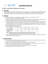
Figure 2-1 shows a 5009 control system’s main chassis. The system is housed in
a chassis which may be mounted (by flanges on its back side) either to a panel
or within a cabinet. This chassis consists of three six-slot kernel sections. Each
kernel section is isolated from the other two. With this configuration the failure of
any one section will not cause a shutdown.
Each kernel section includes a kernel power supply, a CPU, an analog I/O
module, and a discrete I/O module. Slot-to-slot logic and power connections are
made through an etched-circuit motherboard located on the back of the chassis.
See Figure 2-1. The motherboard and modules are all VERSAmodule Eurocard
(VME) type. I/O connections are made through cables from the front of the
modules to termination modules in the cabinet. See Figures 4-18 and 4-19 for an
overview of the main chassis, control modules, and termination modules.
From a module connector standpoint, any I/O module can be installed in any of
the chassis slots designated for I/O modules. However, when the application
software is designed, each module is assigned to a specific slot, thus the
software expects each specific I/O module to always be in its designated slot.
The 5009 control chassis is cooled by forced air. In order not to starve modules
of air flow, either a module or a blank module must be installed and secured in
each slot. Cooling fans are located on the top of the main chassis; with one fan
per 6-slot card rack. The power supply chassis contains two cooling fans: one on
top and one on the bottom of the chassis. See Figure 2-1. These fans run any
time the 5009 chassis is powered up.

Manual 85580V2 5009 Installation/Hardware
Woodward 3
Figure 2-1. Control and Power Chassis
System Power Supplies
The 5009 control contains two types of power supplies; main power supplies and
kernel power supplies. The control’s power chassis contains two plug-in main
power supplies, which provide 24 V to each kernel section (A, B, C) of the 5009
control. Mounted in the main control chassis are three Kernel Power Supplies,
which convert 24 V to 5 V at 10 A for their kernel’s CPU and I/O modules.

5009 Installation/Hardware Manual 85580V2
4 Woodward
The system’s main power supplies are housed in a chassis that may be mounted
(by flanges on its back side) either to a panel or within a cabinet. See Figure 2-1.
This chassis contains slots for two 5009 main power supplies, and allows any
main power supply to be used in either slot. A motherboard located on the back
of the chassis allows the two main power supplies to form a fault-tolerant power
system providing six separately regulated, 24 V, 6 A outputs (three from each
power supply) to the control. The six separate outputs are then wired together to
provide load-shared Pwr “A”, Pwr “B”, and Pwr “C” outputs. Each output provides
up to 6A that are wired to the MicroNet TMR
®
chassis (reference Figure 3-3).
Power output regulation, including line, load, and temperature effects, is better
than ± 5%.
When both main power supplies are running, current sharing circuitry balances
the load to reduce heat and improve reliability of the power supplies. In the event
one supply needs replacement, this feature also ensures bumpless hot
replacement of the power supplies, without disrupting the operation of the
control. Latent fault detection is used to detect and report any power supply
failures to the CPU’s in the control.
Input power connections are made to the main power supply through terminals
on the front of the power supplies. For convenience, when a system is provided
with a cabinet, input power connections are made through panel mounted
Phoenix type terminal blocks. See Figure 4-20. A standard 50-pin ribbon cable is
used for connecting the power supply chassis to the 5009 control chassis.
A set of two main power supplies are provided with each system. Each power
supply set can consist of any two of the three available power supply models,
and in any combination. For instance, a set of one 24Vdc power supply and one
120 Vac power supply may be used to power the 5009 control depending on
whichever power source is available. Different models of power supplies allow
the control to interface with different input source voltages.
Main power supplies are available in the following models:
LVDC – 18-32 Vdc
AC/DC – 88–132 Vac or 100–150 Vdc
HVAC/DC – 180–264 Vac or 200–300 Vdc
Each Main Power Supply has four LEDs to indicate power supply health (OK,
Input Fault, Overtemperature, Power Supply Fault). Refer to Chapter 5 of this
manual for detailed explanations of all LEDs.
Module Descriptions
Physical Description
All chassis mounted control modules are VME-type (VERSAmodule Eurocard)
modules.
Modules slide into card guides in the 5009 control’s chassis and plug into the
motherboard. All modules have their circuitry on a single printed-circuit board.
Each module has a front panel extending from the bottom to the top of the
cabinet.
The modules are held in place by two screws: one at the top and one at the
bottom. Also at the top and bottom are two handles which, when toggled, move
the modules out just far enough for the boards to disengage the motherboard
connectors. Each module is protected with a molded plastic cover to prevent
accidental component damage.

Manual 85580V2 5009 Installation/Hardware
Woodward 5
Kernel Power Supply Module (A1)
Each Kernel Power Supply module receives 24 Vdc from the main power
supplies and provides regulated 5 Vdc and 5 V pre-charge power sources to the
other kernel modules (CPU and I/O modules). The 5 Vdc power source is used
by each module in the kernel section to power its microprocessor. The 5 V pre-
charge power supply is only used as a pre-charge power source to allow all I/O
modules to be hot replaceable. The 24 Vdc power from the main power supplies
is routed through this module to the other kernel modules to allow all kernel
power to be completely removed when this module is not installed. This module’s
health and operation is monitored and verified by its respective kernel CPU.
Figure 2-2. Kernel Power Supply Block Diagram
Central Processor Unit (CPU) Module (A2)
This module, following the instructions of the application program, controls the
circuits of the 5009 control so that they perform all the required control and
sequencing functions. There are three CPU modules provided with each system.
Figure 2-3 is a diagram of a 5009 CPU module. Each CPU utilizes a Motorola
68040 microprocessor to perform its data processing. The VME bus arbitrator
block controls the VME bus and determines what device may use the bus when
there is a conflict.
An RS-232 Serial Port is located on the front of each CPU to interface with the
PCI engineering workstation, OpView or other RS-232 compatible devices.
The CPU has a PCMCIA (Personal Computer Memory Card International
Association) slot on its front panel. The PCMCIA slot is used to down load
application files to the CPU module.

5009 Installation/Hardware Manual 85580V2
6 Woodward
The CPU module has a battery to power the Real Time Clock, even when power
to the control is off. This battery is not user-replaceable. During normal operation
onboard circuitry keeps the battery charged at all times. Once the battery is fully
charged (16 hours) the battery will continue to run the clock for a minimum of
three months without power to the control. Should the CPU not be powered for
several months and the battery loses it’s charge, the Real Time Clock will need
to be set once the CPU is powered up. The module will automatically recharge
the battery once powered. See the battery specifications in Chapter 6.
Figure 2-3. CPU Module
CPU Port Filter Assembly
The CPU module’s front serial port is sensitive to cable noise. Noise form
external sources (relays, breakers, ESD, etc.) couples onto the attached serial
cable, and into the CPU. Noise of this nature can cause temporary CPU failures.
Three filter assemblies (one per CPU) are provided with each system to protect
the CPU from external system noise. These filter assemblies are shipped
separately from the control and can be easily installed if use of the CPU port is
required.

Manual 85580V2 5009 Installation/Hardware
Woodward 7
Figure 2-4. CPU Communications Port Filter Kit Installation Instructions

5009 Installation/Hardware Manual 85580V2
8 Woodward
MPU and Analog I/O Module (A3)
Each analog module contains circuitry for four speed sensor inputs, eight analog
inputs, four analog outputs, and two proportional actuator outputs. An on-board
micro-controller scales inputs and outputs using calibration constants stored in
EEPROM, and schedules outputs to occur at the proper time. Refer to Figure
2-5. This module includes no potentiometers and requires no calibration. When a
channel or module fault is detected, the control annunciates the fault, disables
the channel or module and does not use the channel/module’s data in system
calculations or control.
Each CPU sends and receives information to and from its respective MPU &
Analog I/O module via the VME bus. Each input value is stored in a register and
addressed by the CPU as required. Outputs are driven by the CPU, through the
module’s associated output drivers.
Figure 2-5. MPU and Analog I/O Module
Analog Termination Modules
Analog Termination Modules (ATMs) mount external to the 5009 chassis on a
standard DIN rail. The analog termination modules are used to connect analog
field wiring to the 5009 control. An ATM houses circuitry to:
• route each input signal to the system’s three independent (rack mounted)
analog modules
• produce each output signal by summing the three independent analog
modules’ respective outputs

Manual 85580V2 5009 Installation/Hardware
Woodward 9
Two ATMs are provided and used with each 5009 control. Refer to Figure 4-19
for an overview of modules and ATMs used. Each ATM connects to the control’s
three independent “MPU & Analog I/O” modules through individual cables, and
provides a common cage-clamp terminal connection for customer field wiring. An
ATM contains circuitry for two speed sensor inputs, four analog inputs, two
analog outputs, and one proportional actuator output.
Because of the differences between sensing circuitry required to interface with
passive (MPUs) and active (proximity) probes, separate ATM terminations are
provided for each probe type. This allows a simple method of field selecting the
type of speed input based on the type of probe used. Depending on a MPU’s
limitations, each MPU input can be jumper-configured to allow it to drive either
two or three inputs (some MPUs cannot drive three inputs). See Chapter 6 of this
manual for MPU input impedance information. A fused 24 Vdc source, with
isolation diodes on the power, common, and output source lines, is provided for
each speed input to power system proximity probes. Each ATM contains circuitry
to interface with 12 V or 24 V proximity probes.
Analog inputs may be used with two-wire ungrounded (loop powered)
transducers or isolated (self-powered) transducers.
All analog and actuator output circuits allow each kernel to contribute one third of
the output’s total current. For dual coil actuators, kernels A and B drive one coil
and kernel C drives the second coil. Current readback circuitry identifies failed
modules and allows the remaining outputs to be adjusted accordingly.
Figure 2-6. Analog Termination Module Diagram

5009 Installation/Hardware Manual 85580V2
10 Woodward
Discrete I/O Module (A4)
Each Discrete input/output (I/O) module receives status information from 24
discrete inputs, controls 12 relay outputs and provides latent fault detection for
each relay output. Field wiring is isolated from the 5009 circuitry through optical
isolators on each input channel, and relays on each output channel.
Figure 2-7 is a diagram of the Discrete I/O module. Each CPU sends and
receives information to and from its respective Discrete I/O module via the VME
bus. Each input status is stored in a register and addressed by the CPU as
required. Output commands are driven by the CPU to the Discrete I/O module’s
associated output latches. These latches control the state of output drivers to
energize and de-energize relays. Output Relays are located on the Discrete
Termination Modules.
Each output channel has a readback buffer that stores and indicates the status of
the output driver and associated relays. The CPU compares this status to the
value written to the channel and generates a fault signal if these values are
different.
Figure 2-7. Discrete Input/Output Module
Discrete Termination Modules (F/T Relay Module)
Discrete Termination Modules (DTMs) mount external to the 5009 chassis on a
panel or in a cabinet. The discrete termination modules are used to connect
discrete field wiring to the 5009 control. Four DTMs are provided and used with
each 5009 control. Refer to Figure 4-19 for an overview of modules and DTMs
used. Each DTM connects to the control’s three independent Discrete I/O
modules through individual cables, and provides a common cage-clamp terminal
connection for customer field wiring. A DTM contains circuitry for six contact
inputs, three relay outputs and houses circuitry to:

Manual 85580V2 5009 Installation/Hardware
Woodward 11
• route each contact input signal to the system’s three independent (rack
mounted) discrete modules
• provide an open / closed contact output based on associated discrete
module commands
• indicate the health of all relays (latent fault detection)
WARNING—HAZARDOUS LOCATIONS
This equipment is not suitable for use in Class I, Division 2 hazardous
locations if an F/T Relay module is installed in the cabinet. It must be used in
ordinary or non-hazardous locations only.
Discrete input power (contact wetting voltage) can be supplied by the 5009
control or from an external source. The 5009 control provides an isolated 24 Vdc
power source for contact wetting. The external source may be 24 Vdc or 125 Vdc
(North American installations only). Separate discrete input terminals are
provided based on the level of contact wetting voltage used. See Figure 4-9.
CAUTION—MAXIMUM VOLTAGE
To comply with CE Marking under the European Low Voltage Directive
(LVD), the maximum external circuit voltage for both the Discrete Inputs and
Relay Output circuit are limited to 18–32 Vdc maximum.
The discrete output relays are mounted on sockets, with 18 relays per DTM. Six
relays, are used to create each relay output (normally open and normally closed
contacts) and allow latent fault detection. See Figure 4-15. This configuration
allows independent testing of each relay output (latent fault detection) without
concern of relay position. Customer power is connected to one side of the
configuration and load to the other.
Discrete outputs can be configured to use latent fault detection to identify output
relay failures without affecting operation. When the contacts are closed, they are
periodically opened in pairs, to ensure that they are in the correct state, and that
they change state. When they are open, they are periodically closed individually,
to ensure that they close. Any failures are annunciated, and further testing is
disabled.

5009 Installation/Hardware Manual 85580V2
12 Woodward
Figure 2-8. DTM Block Diagram
SIO Module
The SIO module is provided with the system. This control system is capable of
utilizing two SIO modules at any time. These modules are installed in slot 5 of
the A and B kernels. Each SIO module includes four serial ports. Ports 1 and 2
are RS-232 communications based ports only. Ports 3 and 4 can be configured
for RS-232, RS-422, or RS-485 communications. Refer to Chapter 4 of this
volume for port related communication capabilities.
Page is loading ...
Page is loading ...
Page is loading ...
Page is loading ...
Page is loading ...
Page is loading ...
Page is loading ...
Page is loading ...
Page is loading ...
Page is loading ...
Page is loading ...
Page is loading ...
Page is loading ...
Page is loading ...
Page is loading ...
Page is loading ...
Page is loading ...
Page is loading ...
Page is loading ...
Page is loading ...
Page is loading ...
Page is loading ...
Page is loading ...
Page is loading ...
Page is loading ...
Page is loading ...
Page is loading ...
Page is loading ...
Page is loading ...
Page is loading ...
Page is loading ...
Page is loading ...
Page is loading ...
Page is loading ...
Page is loading ...
Page is loading ...
Page is loading ...
Page is loading ...
Page is loading ...
Page is loading ...
Page is loading ...
Page is loading ...
Page is loading ...
Page is loading ...
Page is loading ...
Page is loading ...
Page is loading ...
Page is loading ...
Page is loading ...
Page is loading ...
Page is loading ...
Page is loading ...
Page is loading ...
Page is loading ...
Page is loading ...
Page is loading ...
Page is loading ...
Page is loading ...
Page is loading ...
Page is loading ...
Page is loading ...
Page is loading ...
Page is loading ...
Page is loading ...
Page is loading ...
Page is loading ...
Page is loading ...
Page is loading ...
Page is loading ...
Page is loading ...
Page is loading ...
Page is loading ...
Page is loading ...
Page is loading ...
Page is loading ...
Page is loading ...
Page is loading ...
Page is loading ...
Page is loading ...
Page is loading ...
Page is loading ...
Page is loading ...
Page is loading ...
Page is loading ...
Page is loading ...
Page is loading ...
Page is loading ...
Page is loading ...
Page is loading ...
Page is loading ...
Page is loading ...
Page is loading ...
Page is loading ...
Page is loading ...
Page is loading ...
Page is loading ...
Page is loading ...
Page is loading ...
/