Page is loading ...

OPERATING and MAINTENANCE
INSTRUCTIONS
MAXIS® 6K Puller
(M6K-M)
READ AND UNDERSTAND ALL OF THE
INSTRUCTIONS AND SAFETY INFORMATION IN
THIS MANUAL BEFORE OPERATING OR
SERVICING THIS TOOL
04/17 (M6K-M)

1
TABLE OF CONTENTS
Important Safety Information.................................................2 - 5
Description of Operation.............................................................6
Identification................................................................................6
Setup and Operation............................................................7 - 17
Troubleshooting and Maintenance............................................17
Warranty.............................................................................19 - 20
SAFETY FIRST
Safety is essential in the use and maintenance of Southwire™
Contractor Equipment. This instruction manual and any markings
on the tool provide information for avoiding hazards and unsafe
practices related to the use of this tool. Observe all of the safety
information provided.
SAFETY ALERT SYMBOLS
These symbols are used to call attention to hazards or unsafe
practices related that could result in injury or property damage.
The three safety words defined below indicate the severity of the
hazard. The message after the signal word provides information
for preventing or avoiding the hazard.
2
DANGER - immediate hazards that if not avoided WILL
result in severe injury or death
WARNING - Hazards that if not avoided COULD result in
severe injury or death
CAUTION - Hazards or unsafe practices that, if not
avoided MAY result in severe injury or death

DANGER: Electrical Shock Hazards.
• Only qualified persons should operate the MAXIS
®
6K
• Wear eye protection, hard hat, cut resistant gloves and safety
toe shoes when using this tool.
• Do not use tool while tired or under the influence of drugs,
alcohol, or medication.
• Keep body parts and loose clothing away from moving parts.
• Always follow operating procedures.
• Avoid accidental starting. Make sure switch is off before
plugging in motor.
• Do not expose power tools to rain or wet conditions. Water
entering a power tool can increase the risk of electric shock.
• Plug into a (GFCI) ground fault interrupted circuit outlet only.
• Use a 10/3 20 Amp 120 Volt extension cord no more than 100
feet in length.
• Maintain proper care of power cords. Do not use the cord to
carry the tool or pull the plug from an outlet. Replace damaged
cords immediately. Damaged cords can increase the risk of
electric shock.
• Do not use this tool near live circuits. Shut off and lock out
power when working near existing circuits.
FAILURE TO OBSERVE THESE WARNINGS COULD
RESULT IN SEVERE INJURY OR DEATH.
WARNING - Personal Safety Hazards
WARNING
• Read and understand all instructions and safety information in
this manual before operating or servicing this tool.
• Read the instruction manual supplied with your drill before
operating the Maxis® 6K puller.
• Failure to observe these warnings could result in severe injury
or death.
3
IMPORTANT SAFETY INFORMATION
FAILURE TO OBSERVE THESE WARNINGS COULD
RESULT IN SEVERE INJURY OR DEATH.
WARNING: Tool Use Hazards
• Use this tool for the manufacturer`s intended purpose only.
Use other than that which is described in this manual can result
in injury or property damage.
• Do not use nylon or polypropylene rope, extreme force can be
stored when rope stretches.
4
IMPORTANT SAFETY INFORMATION
WARNING: Entanglement Hazard
WARNING:Tipping
• Do not operate this tool while wearing loose-fitting clothing.
Retain long hair.
• Keep hands away from the puller’s capstan. Rope at the capstan
can crush a hand.
• Turn off drill when wrapping rope on capstan.
FAILURE TO OBSERVE THESE WARNINGS CAN RESULT
IN SEVERE INJURY OR DEATH.
FAILURE TO OBSERVE THIS PRECAUTION CAN RESULT
IN INJURY OR PROPERTY DAMAGE.
FAILURE TO OBSERVE THESE WARNINGS COULD RESULT
IN SEVERE INJURY OR DEATH.
• Use the appropriate size adaptor with conduit. Lock adaptor
under conduit nut. Disassemble when not in use.

5
The Maxis® 6K is a a cable puller intended to pull medium to large
wire (up to 750MCM) wire through conduit. It sets up in only
minutes, operates at both 12 feet per minute in low and 44 feet per
minute in high and will pull up to 6,000 pounds without being
bolted to the ground. The Maxis® 6K requires only one person to
set up and operate.
IMPORTANT SAFETY INFORMATION
IDENTIFICATION
6
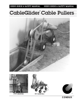
DESCRIPTION OF OPERATION
1. Conduit Adaptors (size 2, 2-1⁄2, 3, 3-1⁄2, 4 inch)
2. Adaptor Housing bracket
3. Adaptor bolt 5/8 inch
4. Front Roller
5. Front Extension
6. Main Roller
7. Main Roller Hitch Pin (4-1⁄2 x 1⁄2)
8. Front Extension Hitch pin (4-1⁄2 x 1⁄2)
9. Adjustable Outer Sleeve
10. Clevis Pin
11. Capstan
12. Drill Chuck Adaptor
13. Gear Box
14. Switch Lever (on/off)
15. Drill Mount
16. Lower Fixed Leg
17. Lower Pulley
18. Base Plate
19. Base Plate Pin
20. Drill Mount Bolt
CAUTION:
• Read and understand all of the instructions and safety information
in this manual before operating or servicing this tool.
CAUTION:
• Do not use if any parts are damaged as this can cause an unsafe
condition and lead to tool malfunction or failure.
• If tool is in disrepair, DO NOT USE. Have tool serviced at an
Authorized Southwire Repair Center.
FAILURE TO OBSERVE THESE CAUTIONS CAN RESULT IN
INJURY OR PROPERTY DAMAGE
FAILURE TO OBSERVE THESE CAUTIONS CAN RESULT IN
INJURY OR PROPERTY DAMAGE
• Inspect all aspects of the pull to ensure safety.
• Only qualified personnel should use pulling equipment.
• Do not use the cable puller as hoist or winch. The cable puller
cannot lower a load. The load may fall and cause serious injury
or death.
1
23
4
5
8
6
7
10
11
12
15
20
14
19
18
17
16
13
9
1

7 8
SET UP AND OPERATION SET UP AND OPERATION
1. Slide the axle through the wheel slots on the back of the Pull
Cart (Fig 1).
2. Place one washer on the axle between the cart frame and
the wheel, then slide the wheel onto the axel followed by a
second washer (Fig 2-3).
3. Use a cotter pin (butterfly pin) to hold the wheel in place
(Fig 4). Bend the cotter pin to lock the assembly (Fig 5) Note:
You may need to use pliers to hold the pin in place while
bending the pin with needle nose (Fig 4a).
4. Repeat steps 2 and 3 on the opposite side of the cart for the
second wheel.
PULLER CART SETUP
Wheel Assembly Includes:
(2) Cotter Pins
(4) Washers
(2) Wheels
(1) Axle
Main Assembly Includes:
(1) Cart
(2) Cotter Pins
(1) Attachable Accessory Bag
Dimensions
L17.5” x W21” x H50”
Total weight 35 lbs.
(w/o cable puller, motor or conduit
adapters)
Description
Stock #- 56-82-96-01
Model #- PC100
Aa
WHEEL ASSEMBLY
Fig 1 Fig 2
Fig 3 Fig 4
Fig 5 Fig 6

109
ATTACHING THE TOOL BAG
SET UP AND OPERATION SET UP AND OPERATION
1. Separate the top three strips of hook and loop from each
other.
2. Rewrap them tightly around the top bar main frame behind
the handle of the cart (Fig 1).
3. Separate both side strips of hook and loop from each other.
4. Rewrap each side tightly around the side mainframe of the
Cart (Fig 2).
ATTACHING THE PULLER
1. Once the wheel assembly has been completed, be sure that
your Maxis® 3K or 6K is disassembled into two parts (Fig 1).
2. Insert the gearbox portion if the puller into the sleeve
mounted in the middle of the carts carrying plate with the
base plate up (Fig 2).
3. Push the pullers base plate back so the carts anchor shaft
protrudes from the pullers base plate.
4. Install cotter pin through anchor shaft to lock the puller
gearbox section in place (Fig 3). Note: Puller cart anchor
shaft will be positioned on the top right of the support bar
for the Maxis® 3K and on the right of the main frame for the
Maxis® 6K (Fig 3a).
5. Take the pullers front arm extension and slide the sleeve
onto the post on the left side of the carts carry plate (Fig 4).
6. Using the pullers hitch pin, slide pin through one of the
pullers adjustment holes and the mounting hole located on
the left side of the cart (Fig 5-6). Note: Puller cart extension
hole for the Maxis® 3K is located approximately 9 inches
from the top and 6 inches from the top on the Maxis® 6K
(Fig 7).
Fig 1 Fig 2
7. Lock the pullers front arm extension into place by inserting
the cotter pin into the hitch pin (Fig 8).
Fig 1
Fig 2 Fig 3
Fig 3a
Fig 4
Fig 5
Fig 6
Fig 8
Fig 7

1211
SET UP AND OPERATION SET UP AND OPERATION
CONDUIT ADAPTORS
1. To attach conduit adaptors to the cart, slide the adaptor plate
into the mounting slot on the back of the cart. Pull spring
locking fasteners for easy storage and removal of conduit
adaptors. Compatible with both Maxis® 3K and Maxis® 6K.
Be sure to store 1” and 1-1/2” conduit adaptors in the tool
bag when utilizing the Maxis® 3K adaptors.
PUTTING PULLER TOGETHER
1. Always wear gloves, eye protection, hard hats and safety
toed shoes when working with pullers.
2. Remove gearbox assembly from cart and lay on the ground.
3. Lay front extension assembly face down; remove clevis pins
on extension assembly.
4. Slide 2” outer sleeve over gearbox assembly and reinstall
clevis pin (Fig 1).
5. Slide drill in place over drill chuck adaptor and tighten all
three holes of the chuck, (if this is not done the drill may slip
on the shaft) Do not tighten just one chuck hole (Fig 2-3).
6. Secure drill in place with drill mount bolt (Fig 4).
7. Maxis® 6K was designed to be used with the Milwaukee
Super Hawg® drill.
8. Set the motor to the desired speed, H or L (Fig 5).
ATTACHING THE CONDUIT ADAPTORS
Option 1
1. Remove 6-1⁄2 x 1⁄2” hitch pin on front extension (not the
pin with the roller), swing front extension forward and install
conduit adapter (size 2, 2-1/2, 3, 3-1/2 and 4 inch) (Fig 6).
2. Secure with 5/8” bolt to hold in place (Fig 7).
3. For tight pulling situations, the bottom half of the adapter
can be removed by unscrewing the two side hex screws.
Fig 5Fig 4
Fig 1 Fig 2 Fig 3
Fig 7Fig 6

UNDERGROUND PULLS
1413
SET UP AND OPERATION SET UP AND OPERATION
1. Assemble puller and attach correct size conduit adaptor.
2. Pivot Front Extension assembly to desired angle and
reinsert pin (Fig 11).
3. Lift front end and place conduit adapter into conduit.
Always make sure the conduit adaptor sits flush around the
conduit you are pulling through (Fig 12).
4. Replace pin front assembly to lock all parts tight. (This must
be pinned for the puller to operate properly and safely).
5. WARNING: Do not stand in line with the rope being pulled
(stand to the side of the drill) to avoid injury if rope breaks.
6. Use Southwire NoLUBE®SIMpull® cables or add proper
lubricant for all your pulling jobs.
7. Loosely wrap rope around the capstan in a clockwise
direction from the inside out. Start the electric drill by
rotating the Maxis® 6K’s switch lever. Pull on the rope to
produce some tension. The rope will begin to advance.
8. Maintain tension on the rope.
• The rope will slip on the capstan during normal operation.
Keep the rope moving so that the capstan does not contact
one spot on the rope for more than a few seconds.
Otherwise, the rope will heat up quickly and it may break.
• Do not exceed about 45 N (10lb) of tension on the rope. If the
pull becomes difficult, stop the pull, add another wrap or two
of rope to the capstan. WARNING: Do not add wraps to
Capstan with motor running, could result in Injury or death.
• If excessive force becomes necessary, stop the pull and
inspect the setup.
• When the cable or wire comes over the roller, switch the
electric drill OFF.
Option 2
1. Place desired conduit adaptor into conduit (Fig 8).
2. Slide front end extension onto adaptor (Fig 9).
3. Secure with 5/8” bolt to hold into place (Fig 10).
Underground Pull
Fig 11
Fig 12
Fig 9Fig 8 Fig 10

• The rope will slip on the capstan during normal operation.
Keep the rope moving so that the capstan does not contact
one spot on the rope for more than a few seconds.
Otherwise, the rope will heat up quickly and it may break.
• When pulling on the rope, do not exceed about 45 N (10lb)
of tension on the rope. If the pull becomes difficult, stop the
pull, add another wrap or two of rope to the capstan.
WARNING: Do not add wraps to Capstan with motor
running, could result in Injury or death.
• If excessive force becomes necessary, stop the pull and
inspect the setup.
• When the cable or wire comes over the roller, switch the
electric drill OFF.
OVERHEAD PULLS
1615
SET UP AND OPERATION SET UP AND OPERATION
1. Assemble puller and attach correct size conduit adaptor.
2. To convert to overhead pulls, remove front hitch pin on front
extension and swing front extension straight out and re-pin
(Fig 13).
3. Remove upper pin from adjustable outer sleeve and front
assembly and turn front assembly 180° and re-pin (Fig 14)
4. Shorten the length of the adjustable outer sleeve then extend
arm to fit into conduit. Always make sure conduit and adaptor
sits flush around the conduit you are pulling through. Thread
rope under front roller and over main roller (Fig 15).
5. Pin Adjustable Outer Sleeve (Fig 16).
6. WARNING: Do not stand in line with the rope being pulled
(stand to the side of the drill) to avoid injury if rope breaks.
7. Use Southwire NoLUBE® SIMpull® cables or add proper
lubricant for all your pulling jobs.
8. Loosely wrap rope around the capstan in a clockwise direction
from the inside out. Start the electric drill by rotating the
Maxis® 6K’s switch lever. Pull on the rope to produce some
tension. The rope will begin to advance.
9. Maintain tension on the rope.
Fig 13
Underhead Pull Fig 14
Fig 15 Fig 16

18
PULLING OUT EXTRA WIRE
1. When wire appears out of conduit and down pullers shaft,
turn off dill motor.
2. Unwrap rope from capstan and extend rope around Lower
Pulley then back up to capstan (Fig 17).
3. Wrap rope around the capstan in a clockwise direction from
the inside out.
4. Continue wire pull until desired length is pulled out or until
wire reaches lower pulley.
TROUBLESHOOTING
1. Make sure capstan rotates in a clockwise rotation. If
rotating in a counter clock rotation the drill motor is in
reverse, turn off drill and switch the motor to the forward
rotation.
2. Tighten all three chuck holes when attaching drill to chuck
adaptor. Check drill chuck for tightness before every pull.
MAINTENANCE
• Gearbox is filled with high temperature lubricating grease.
No maintenance is required.
• Drill shaft is equipped with a six sided harden steel extension.
If you chuck all three chuck holes you should not have
slipping. If for any reason this shaft is worn down or stripped,
call your local distributer or Southwire Tools and Equipment
for a replacement.
SPECIFICATIONS
• Model# M6K-M
• Stock # 57-64-84-01
• Length (Fully Extended)- 10 Feet
• Length Disassembled- 40 Inches
• Width- 8 Inches
• Weight with Motor – 155lbs
• Pulling Rope Minimum Average Breaking Strength-
18,000lbs
• Pulling Speed Low- 12 fpm (No Load)
• Pulling Speed High- 44 fpm (No Load)
• Recommended Pulling Rope- 5/8 Inch or Larger
• Patent Number – US 6,682,050
Fig 17
17
SET UP AND OPERATION EXPLODED DIAGRAM
P3-203A
P3-206
P3-206-1
P6-207
P6-118
P6
-
205
P3-206-1
P6-002
P6-002-4
P6-002-2
P6-002-1
P6-204
P3-33
P6-209
P6-17
P6-10
P6-202
P6-201
P6-
00218
P6-
00218
P6-203
P6-203
P6-13
P6-122
P6-122
P6-118
P6-208-51
P6-208-52
P6-208-57
P6-122
P6-208-53
(2``)P6-208-55A
(2-1/2``)P6-208-55B
(3``)P6-208-55C
(3-1/2``)P6-208-55D
(4``)P6-208-55E

2019
Warranty Claim Information/How Do You Get Service?
For all warranty, customer service, and product return authorizations and inquiries,
please contact Southwire’s Tools & Assembled Products at:
840 Old Bremen Road
Carrollton, GA, 30117
Repair Your Product When it is Out of Warranty
Southwire is happy to provide information about where a purchaser can send a product for
repair at consumers’ own expense, please contact 1.855.SW.tools or visit
www.southwiretools.com/tools/home.do for more information about servicing for Southwire
Products.
WARRANTY ON
SOUTHWIRE CONTRACTOR EQUIPMENT
What Does This Warranty Cover?
Five-Year Limited Warranty on Contractor Equipment
Under Southwire’s Contractor Equipment 5-Year Limited Warranty, Southwire Company, LLC
warrants that all Southwire Contractor Equipment will be free from manufacturer defects for a
period of five (5) years from the date of the original end user’s purchase. However, electrical
components and consumable parts such as ropes, blades, dies, draw studs, grips, are
excluded from this 5-Year Limited Warranty and are subject to the One -Year warranty terms.
Under this 5-Year Limited Warranty, the following are also excluded and Southwire
Company, LLC will have no liability for any of the following: normal wear and tear resulting
from product use and damage arising out of misuse, abuse, modification, and improper
product maintenance. This warranty also does not cover Southwire Contractor Equipment
products that have been modified by any party other than Southwire Company, LLC or its
authorized third party designee. This 5-Year Limited Warranty is not transferrable to or
enforceable by any person other than the product’s original end user.
One-Year Limited Warranty on Electrical Components and Consumable
Parts (with 5-Year warranty)
Under Southwire’s 1-Year Limited Warranty, Southwire Company, LLC warrants that all
electrical components and consumable parts such as ropes, blades, dies, draw studs, grips
will be free from manufacturer defects for a period of one-year from the date of the original
end user’s purchase. Under this 1-Year Limited Warranty, Southwire Company, LLC will have
no liability for any of the following: normal wear and tear resulting from product use and
damage arising out of misuse, abuse, modification, and improper product maintenance. This
warranty also does not cover Southwire electrical components and consumable parts that
have been modified by any party other than Southwire Company, LLC or its authorized third
party designee. This 1-Year Limited Warranty is not transferrable to or enforceable by any
person other than the product’s original end user.
Exclusion of Incidental, Consequential, Indirect, Special and Punitive Damages
Some states do not allow the exclusion or limitation of incidental or consequential
damages, so the above limitation or exclusion may not apply to you.
1. All warranty claims must be approved by Southwire’s Tools & Assembled Products
Warranty Department prior to return of product. If Southwire determines that a product is
defective, Southwire will, at its option, repair or replace defective products or defective
product components, free of charge.
2. Upon approval, Southwire will issue a Product Return Authorization Form which will include
instructions on how and where to return the product. The product serial number and the
original date of delivery must be set forth on the Product Return Authorization Form.
3. Southwire will cover standard freight charges (Ground Courier Rate) incurred in connection
with products that Southwire ultimately determines to be defective.
4. All defective components and defective products that Southwire replaces under these
Warranties will become Southwire’s property and will be retained by Southwire.
/