Greenlee 52087815 REV 1 - G1 IM.pdf User manual
- Type
- User manual

OPERATION MANUAL
Read and understand all of the instructions and
safety information in this manual before operating
or servicing this tool.
Register this product at www.greenlee.com
52087815 REV1 © 2019 Greenlee Tools, Inc. 10/19
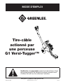
G1 Versi-Tugger™
Drill-Powered
Cable Puller
Español................25–46
Français...............47–68

G1 Versi-Tugger™
Greenlee Tools, Inc. 4455 Boeing Dr. • Rockford, IL 61109-2988 USA • 815-397-7070
2
Description
The Greenlee G1 Versi-Tugger™ is intended to be used
to pull cable through conduit and in tray. The G1 Versi-
Tugger is an attachment for pistol grip style 12-20V
cordless drills. The G1, coupled with a standard drill
or hammer drill driver such as the Makita XFD07, will
develop up to 1000lbs (4.45kN). Refer to a Greenlee
catalog for sheaves, pulling rope, and other cable
pulling accessories to create an entire cable pulling
system. No single manual can provide instructions for
every possible cable pulling application; this manual
contains general information necessary to accomplish
cable pulls of many different setups.
Safety
Safety is essential in the use and maintenance of
Greenlee tools and equipment. This instruction manual
and any markings on the tool provide information for
avoiding hazards and unsafe practices related to
the use of this tool. Observe all of the safety
information provided.
Purpose of this Manual
This manual is intended to familiarize all personnel with
the safe operation and maintenance procedures for the
Greenlee G1 Versi-Tugger Drill-Powered Cable Puller.
Keep this manual available to all personnel.
Replacement manuals are available upon request at no
charge at www.greenlee.com.
All specications are nominal and may change as design
improvements occur. Greenlee Tools, Inc. shall not be liable for
damages resulting from misapplication or misuse of its products.
® Registered: The color green for cable pulling equipment is a
registered trademark of Greenlee Tools, Inc.
KEEP THIS MANUAL
Table of Contents
GENERAL SAFETY ................................................3–4
SPECIFIC SAFETY .................................................5–7
CABLE PULLING OVERVIEW
Cable Pulling Glossary ............................................... 8
Planning the Pull ......................................................... 8
FUNCTIONAL DESCRIPTION
Identication ......................................................... 9-10
Specications ........................................................... 11
OPERATION
Mounting Cordless Drill to Puller .............................. 12
Head and Boom Operation .......................................... 13
Puller Operation .................................................. 14-15
Spooling Pulling Line/Mule Tape ................................... 14
Capstanning ................................................................... 15
Mounting a Monopod .................................................... 16
Attaching a Boom Extension ........................................ 17
EXPLODED VIEW AND PARTS LISTS
G1 Versi-Tugger Puller ........................................ 19-21

G1 Versi-Tugger™
Greenlee Tools, Inc. 4455 Boeing Dr. • Rockford, IL 61109-2988 USA • 815-397-7070
3
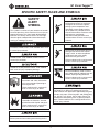
GENERAL SAFETY RULES
WARNING Read all safety warnings, instructions,
illustrations and specifications provided with this
power tool. Failure to follow all instructions listed below
may result in electric shock, re and/or serious injury.
SAVE ALL WARNINGS AND INSTRUCTIONS FOR
FUTURE REFERENCE.
The term "power tool" in the warnings refers to your
mains-operated (corded) power tool or BATTERY
operated (cordless) power tool.
WORK AREA SAFETY
Keep work area clean and well lit. Cluttered or dark
areas invite accidents.
Do not operate power tools in explosive
atmospheres, such as in the presence of flammable
liquids, gases or dust. Power tools create sparks
which may ignite the dust or fumes.
Keep children and bystanders away while operating
a power tool. Distractions can cause you to
lose control.
ELECTRICAL SAFETY
Avoid body contact with earthed or grounded
surfaces, such as pipes, radiators, ranges and
refrigerators. There is an increased risk of electric
shock if your body is earthed or grounded.
Do not expose power tools to rain or wet conditions.
Water entering a power tool will increase the risk of
electric shock.
PERSONAL SAFETY
Stay alert, watch what you are doing and use
common sense when operating a power tool. Do
not use a power tool while you are tired or under the
influence of drugs, alcohol or medication. A moment
of inattention while operating power tools may result in
serious personal injury.
Use personal protective equipment. Always wear eye
protection. Protective equipment such as dust mask,
non-skid safety shoes, hard hat, or hearing protection
used for appropriate conditions will reduce
personal injuries.
Prevent unintentional starting. Ensure the switch is
in the off-position before connecting to power source
and or BATTERY pack, picking up or carrying the tool.
Carrying power tools with your nger on the switch
or energising power tools that have the switch on
invites accidents.
Remove any adjusting key or wrench before turning
the power tool on. A wrench or a key left attached to
a rotating part of the power tool may result in
personal injury.
Do not overreach. Keep proper footing and balance
at all times. This enables better control of the power
tool in unexpected situations.
Dress properly. Do not wear loose clothing or
jewelry. Keep your hair, clothing and gloves away
from moving parts. Loose clothes, jewelry or long hair
can be caught in moving parts.
If devices are provided for the connection of dust
extraction and collection facilities, ensure these are
connected and properly used. Use of dust collection
can reduce dust-related hazards.
Do not let familiarity gained from frequent use of
tools allow you to become complacent and ignore
tool safety principles. A careless action can cause
severe injury within a fraction of a second.
POWER TOOL USE AND CARE
Do not force the power tool. Use the correct power
tool for your application. The correct power tool will
do the job better and safer at the rate for which it
was designed.
Do not use the power tool if the switch does not turn
it on and off. Any power tool that cannot be controlled
with the switch is dangerous and must be repaired.
Disconnect the plug from the power source and/
or remove the BATTERY pack, if detachable, from
the power tool before making any adjustments,
changing accessories, or storing power tools. Such
preventive safety measures reduce the risk of starting
the power tool accidentally.
Store idle power tools out of the reach of children
and do not allow persons unfamiliar with the power
tool or these instructions to operate the power tool.
Power tools are dangerous in the hands of
untrained users.

G1 Versi-Tugger™
Greenlee Tools, Inc. 4455 Boeing Dr. • Rockford, IL 61109-2988 USA • 815-397-7070
4
Maintain power tools and accessories. Check for
misalignment or binding of moving parts, breakage
of parts and any other condition that may affect the
power tool’s operation. If damaged, have the power
tool repaired before use. Many accidents are caused by
poorly maintained power tools.
Keep cutting tools sharp and clean. Properly
maintained cutting tools with sharp cutting edges are
less likely to bind and are easier to control.
Use the power tool, accessories and tool bits etc.
in accordance with these instructions, taking into
account the working conditions and the work to
be performed. Use of the power tool for operations
different from those intended could result in a hazardous
situation.
Keep handles and grasping surfaces dry, clean
and free from oil and grease. Slippery handles and
grasping surfaces do not allow for safe handling and
control of the tool in unexpected situations.
SERVICE
Have your power tool serviced by a qualified repair
person using only identical replacement parts.
This will ensure that the safety of the power tool
is maintained.
GENERAL SAFETY RULES (cont'd)

G1 Versi-Tugger™
Greenlee Tools, Inc. 4455 Boeing Dr. • Rockford, IL 61109-2988 USA • 815-397-7070
5
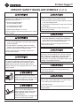
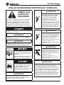
SPECIFIC SAFETY RULES AND SYMBOLS
SAFETY
ALERT
SYMBOL
This symbol is used to call your attention to hazards
or unsafe practices which could result in an injury or
property damage. The signal word, dened below,
indicates the severity of the hazard. The message
after the signal word provides information for pre-
venting or avoiding the hazard.
Immediate hazards which, if not avoided, WILL result
in severe injury or death.
Hazards which, if not avoided, COULD result in
severe injury or death.
Hazards or unsafe practices which, if not avoided,
MAY result in injury or property damage.
Read and understand all of the
instructions and safety information
in this manual before operating or
servicing this tool.
Failure to observe this warning will
result in severe injury or death.
Do not operate the cable puller in
a hazardous environment. Hazards
include ammable liquids and gases.
Failure to observe this warning will
result in severe injury or death.
Do not use this tool near live circuits. Shut off and
lock out power when working near existing circuits
Inspect and verify the maximum
load-bearing capacity or maximum
strength of all structural supports,
pulling system components and
anchoring systems before setting
up the puller. Any component that
cannot withstand the maximum cable
pulling forces could break
and strike nearby personnel with
sufcient force to cause severe injury
or death.
Do not allow anything other than the
pulling line to contact the capstan.
A grip, swivel, or other component
could break and strike nearby
personnel with great force.
Failure to observe this warning could
result in severe injury or death.
Do not stand directly under a vertical
pull. Cable could fall suddenly from the
conduit, injuring nearby personnel.
Failure to observe this warning could
result in severe injury or death.
Only use approved pulling lines and inspect pulling
lines before use. Never use pulling lines that are
under rated for the application. Approved pulling lines
include: mule tape, measuring tape, and pulling (poly)
line. DO NOT use strings, lines or rope that are not
intended for cable pulling such as general-purpose
rope. Failure to observe this warning could result in
severe injury or death.

G1 Versi-Tugger™
Greenlee Tools, Inc. 4455 Boeing Dr. • Rockford, IL 61109-2988 USA • 815-397-7070
6
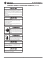
SPECIFIC SAFETY RULES AND SYMBOLS (cont'd)
An under-rated rope may break and whip
violently. Use a cable pulling rope with the
following characteristics:
• Maximum Rated Capacity:
at least 1500 lb (6.7 kN)
• Average Breaking Strength:
at least 6000 lb (26.7 kN)
• Rope Diameter Range: 1/4" to 1/2"
Failure to observe this warning could result in severe
injury or death.
• Check the condition of the entire rope before use.
A worn or damaged rope can break under tension
and whip violently.
• Do not maintain a stationary rope on a rotating
capstan. The wear generated may cause the rope
to break under tension and whip violently.
Failure to observe these warnings could result in
severe injury or death.
Attach the pulling rope to the cable with appropri-
ate types of connectors. Select connectors with
a maximum rated capacity of 1500 lb (6.7 kN). An
under-rated connector can break under tension.
Failure to observe this warning could result in severe
injury or death.
Keep hands away from the capstan.
Rope at the capstan can crush a hand.
Failure to observe this warning could
result in severe injury or death.
Do not wrap rope around hands,
arms, waist or other body parts.
Do not stand in spent coils or tailed
rope. Hold rope so that it may be
released quickly.
Failure to observe this warning could
result in severe injury or death.
Rope, cable, or a connecting device can break under
tension, causing the rope to whip violently.
• Do not allow any unnecessary personnel to remain
in the area during the pull.
• Do not allow any personnel to stand in line with the
pulling rope.
Failure to observe these warnings could result in
serious injury or death.
• Do not allow the rope to overlap on the capstan.
If the rope approaches the top of the angled part
of the capstan, relax the tailing force. If an overlap
does occur, shut off the puller immediately.
Failure to observe these warnings could result in
severe injury or death.
Only use the G1 Versi-Tugger with approved pistol
grip style 12V-20V cordless drills. Do not use the G1
Versi-Tugger with corded drills, right angle cordless
drills, D-handle or spade handle cordless drills,
impact drills, or pistol grip style cordless drills whose
voltage is rated higher than 20V.
DO NOT exceed maximum rated pull force of 1000
lb. Failure to observe this warning could result in
severe injury or death.
Use this tool for manufacturer’s intended purpose
only. Do not use the cable puller as a hoist or winch.
• The cable puller cannot lower a load.
• The load may fall.
Failure to observe this warning could result in severe
injury or death.

G1 Versi-Tugger™
Greenlee Tools, Inc. 4455 Boeing Dr. • Rockford, IL 61109-2988 USA • 815-397-7070
7
SPECIFIC SAFETY RULES AND SYMBOLS (cont'd)
Inspect puller and accessories before use. Replace
any worn or damaged components with Greenlee
replacement parts. A damaged or improperly assem-
bled item can break and strike nearby personnel with
great force.
Failure to observe this warning could result in severe
injury or death.
Entanglement hazard:
• Do not operate the cable puller while wearing
loose-tting clothing.
• Retain long hair.
Failure to observe these warnings could result in
severe injury or death.
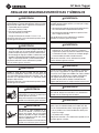
Wear eye protection when using this
tool.
Failure to wear eye protection could
result in severe eye injury from ying
debris.
Wear gloves when using this tool.
Failure to wear gloves could result in
severe injury from ying debris.
Do not alter or modify the G1 VersiTugger in any
way. This includes but is not limited to artically
reinforcing components or using drive keys not
provided by Greenlee.
Do not pin or x trigger in ON position. Do not mount
or attach puller to any object.

G1 Versi-Tugger™
Greenlee Tools, Inc. 4455 Boeing Dr. • Rockford, IL 61109-2988 USA • 815-397-7070
8
CABLE PULLING OVERVIEW
Cable Pulling Glossary
Anchoring system
any item or group of items that keeps a cable pulling
component in place during the cable pull
Capstan
the tapered cylinder of the cable puller that acts on the
pulling rope to generate pulling force
Connector
any item, such as a wire grip, clevis, swivel, or pulling
grip, that connects the rope to the cable
Direct line of pull
the areas next to the pulling rope and along its path;
this includes the areas in front of, in back of, and
underneath the rope
Maximum rated capacity
the amount of pulling tension that any component
can safely withstand, rated in kilonewtons (metric)
or pounds; the maximum rated capacity of every
component must meet or exceed the maximum pulling
force of the cable puller
Pulling grip
connects the rope to the cable; consists of a wire mesh
basket that slides over the cable and grips the insulation
Pulling force
the amount of pulling tension developed by the cable
puller, rated in newtons (metric) or pounds; a cable
puller is usually described by the maximum pulling force
that it can develop
Sheave
a pulley that changes the direction of the rope and cable
Support structure
any stationary object that a cable pulling system
component is anchored to, such as a concrete oor
(for the oor mount) or an I-beam (for a sheave)
Tail
the portion of the rope that the operator applies force
to; this is the rope coming off of the capstan, and is not
under the tension of the pull
Tailing the rope
the operator’s main function; this is the process of
applying force to the tail of the pulling rope—refer to the
complete explanation under “Cable Pulling Principles”
Wire grip
connects the rope to the cable; some use a set screw to
clamp onto the conductors of the cable
Planning the Pull
• Pull in a direction that will require the lowest amount
of pulling force.
• Plan several shorter pulls rather than fewer longer
pulls.
• Locate the puller as close to the end of the conduit
as possible to minimize the amount of exposed rope
under tension.
• Place each component so that the pulling forces are
used effectively.
• Verify that each component has the proper
load rating.
• Inspect the structural supports. Verify that they have
enough strength to withstand the maximum forces
that may be generated.

G1 Versi-Tugger™
Greenlee Tools, Inc. 4455 Boeing Dr. • Rockford, IL 61109-2988 USA • 815-397-7070
9
FUNCTIONAL DESCRIPTION
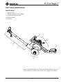
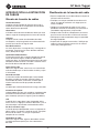
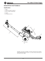
Identification
1. Boom Assembly
2. Capstan and Capstan Wall Assembly
3. Frame and Gearbox Assembly
4. Handle Assembly
5. Drill Strap
Note: for detailed exploded views, please see the Exploded Views and Parts
Lists section of this manual or refer to the G1 Versi-Tugger Service Manual.
1
2
4
5
3

G1 Versi-Tugger™
Greenlee Tools, Inc. 4455 Boeing Dr. • Rockford, IL 61109-2988 USA • 815-397-7070
10
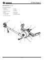
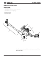
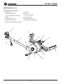
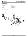
Identification (cont’d)
Assembly Components
6. Capstan
7. Capstan Wall
8. Capstan Wall Knob
9. Boom
10. Boom Adapter
11. Puller Head
12. Puller Head Sheave
13. Frame
14. Handle
15. Gearbox
16. Input Shaft
17. Drill Strap
18. Monopod Adapter
12
9
8
18
6
13
15
16
10
14
7
11
17

G1 Versi-Tugger™
Greenlee Tools, Inc. 4455 Boeing Dr. • Rockford, IL 61109-2988 USA • 815-397-7070
11
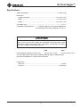
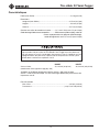
Specifications
Weight (with boom) ................................................................................. 13.8 lb (6.3 kg)
Dimensions
Length (with boom) .........................................................................32.1 in (81.5 cm)
Width .................................................................................................9.7 in (24.6 cm)
Height .............................................................................................. 10.5 in (26.7 cm)
Fits conduit sizes .............................................................................................. 1/2"–4"
Compatible Pulling Rope/Line ........... Pulling line (poly line), polyaramid and polyester
measuring tape (mule tape), pulling rope 1/4” to 1/2”
LOW HIGH
No-Load Speed* (Spooling 430 Poly line) 83 ft/min (25.3 m/min) 308 ft/min (93.9 m/min)
*Assumes drill output in low-speed = 500RPM and high-speed = 2000RPM Note:
pull speed is dependent on cordless drill performance
Pulling Force
Max/Peak ..................................................................................................... 1,000 lb
Constant ................................................................................................. up to 600 lb
Only use the G1 Versi-Tugger with approved pistol grip style 12V-20V cordless
drills. Do not use the G1 Versi-Tugger with corded drills, right angle cordless drills,
D-handle or spade handle cordless drills, impact drills, or pistol grip style cordless
drills whose voltage is rated higher than 20V.

G1 Versi-Tugger™
Greenlee Tools, Inc. 4455 Boeing Dr. • Rockford, IL 61109-2988 USA • 815-397-7070
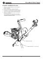
12
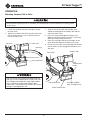
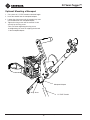
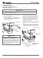
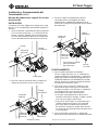
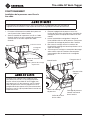
Mounting Cordless Drill to Puller
Use of the drill strap with the G1 is mandatory for safe operation. Failure to observe this warning could
result in injury.
1. Loosen the cordless drill chuck enough to accept
the input shaft.
2. Tighten the cordless drill chuck onto the input shaft.
Ensure the drill chuck is fully seated on the three
ats of the input shaft.
3. Wrap the end of the hook and loop drill strap
around the hand grip of the cordless drill and the
end of the puller frame.
4. Insert the strap end through the buckle on the
opposite side of the frame as the drill. Pull the end
of the drill strap through the buckle.
5. Cinch the strap tight and fasten the hooks on the
strap end to the loops on the body of the strap.
6. Ensure that the strap is free of damage and dirt and
that the hooks are fully engaged with loops of the
drill strap.
Cordless Drill
Input Shaft
Drill Strap Buckle
End of Puller Frame
Drill Strap
OPERATION
Cordless Drill
Drill Strap Buckle
Male
"hook & loop"
Hooks
Drill Strap Looped
Back Through Buckle
Input Shaft
End of Puller Frame
Only use the G1 Versi-Tugger with approved pistol
grip style 12V-20V cordless drills. Do not use the G1
Versi-Tugger with corded drills, right angle cordless
drills, D-handle or spade handle cordless drills,
impact drills, or pistol grip style cordless drills whose
voltage is rated higher than 20V.

G1 Versi-Tugger™
Greenlee Tools, Inc. 4455 Boeing Dr. • Rockford, IL 61109-2988 USA • 815-397-7070
13
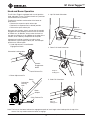
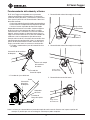
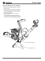
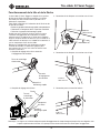
Head and Boom Operation
The G1 Versi-Tugger is equipped with a multi-position
head and boom system. The puller head has 5 positions
and the boom has 4 positions.
To adjust the position or orientation of the boom or
puller head:
• Remove the respective quick release pin
• Reorient the component to its desired position
• Reinsert the quick release pin.
No matter the situation, always ensure that the conduit
engagement notch properly interfaces with the conduit
or conduit nut. In addition, always orient the head so
the rope or pulling line is not rubbing on the edge of the
conduit, or on stationary components of the puller.
Although each pulling situation has unique setup
requirements, typical up-pull, down-pull, and side-pull
positions are shown below:
1. Head-Adjustment Pin and Conduit
Engagement Notch
2. Boom Adjustment Pin
3. Up-Pull Head Orientation
4. Down-Pull Head Orientation
5. Side-Pull Orientation
Boom
Boom
Adapter
Quick-Release Pin
Orientation
Locking
Hole
Rope or
Pulling Line
Rope or
Pulling Line
Rope or
Pulling Line
Note: The lines on the boom indicate the engagement point of each length when lined up with the top of the
mount. You may need to rotate the boom to engage.
Orientation Locking Holes
Quick-Release Pin
Conduit
Engagement
Notch

G1 Versi-Tugger™
Greenlee Tools, Inc. 4455 Boeing Dr. • Rockford, IL 61109-2988 USA • 815-397-7070
14
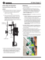
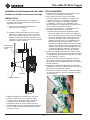
Puller Setup and Operation
Spooling Pulling Line/Mule Tape
SETUP
1. Anchor pulling line/tape to the capstan. There are two
ways to anchor the line to the capstan listed below:
A. Thread the line through the large hole in the
capstan and tie a knot.
-OR-
B. Take the end of the line and clamp it between
the capstan wall and the capstan. This can be
accomplished by unscrewing the capstan wall
about halfway. Then, take the end of the line
and place it between the capstan wall and the
capstan. Finally, screw the capstan wall rmly into
place against the capstan.
2. Adjust the orientation and position of the head and
boom if necessary, ensure the line/tape is anchored
to the capstan. (see previous page 14 “Head and
Boom Operation”). Remember to fully seat the
conduit engagement notch against the conduit or
conduit nut before beginning to pull.
Capstan Wall
Capstan
Pulling Line
or Mule Tape
OPERATION
1. Once the puller has been set up correctly, the pulling
process can begin.
2. With the cordless drill attached to the G1 Versi-
Tugger (see previous page 13 “Mounting Cordless
Drill to Puller”) and the cordless drill direction set to
the FORWARD or CLOCKWISE spinning position,*
depress the trigger of the cordless drill and the
capstan will begin to spin.
3.
When the capstan spins, the pulling line or mule tape
will begin to spool up.
• DO NOT attempt to touch or shift the line while the
capstan is spinning. If an adjustment is necessary,
stop the drill and then make the adjustment.
• It is recommended that when pulling wire or cable
that the cordless drill be operated in LOW speed
to avoid damage to the cable during the pulling
process. Other low force cable pulling scenarios,
like pulling rope into conduit with pulling line (as
setup for a larger cable pull), can be run in HIGH
speed if desired.
4. When the cable pull is complete, the pulling line or
mule tape can be removed. First separate the pulling
line or mule tape from the wire, cable, or rope that
has been pulled.
5. To remove the pulling line/tape when the pull is
complete, unscrew the knob of the capstan wall. Once
fully unscrewed, remove the wall from the capstan.
6. The spool of line or tape can be removed from the
capstan by grasping the line/tape and sliding it off the
end of the capstan.
7. After the pulling line or mule tape has been removed
from the capstan, screw the capstan wall back onto
the capstan.
*See manufacturer instructions for your drill.

G1 Versi-Tugger™
Greenlee Tools, Inc. 4455 Boeing Dr. • Rockford, IL 61109-2988 USA • 815-397-7070
15
Puller Setup and Operation (cont’d)
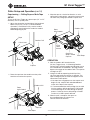
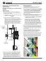
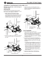
Capstanning — Pulling Rope or Mule Tape
SETUP
To use the G1 Versi-Tugger to capstan rope (1/4” to 1/2”
diameter), rst set up the puller.
1. Adjust the orientation and position of the head and
boom if necessary, see p. 14 “Head and Boom
Operation”). Remember to fully seat the conduit
engagement notch against the conduit or conduit
before beginning to pull.
Puller Head
Cordless Drill
Rope
Capstan
Conduit
2. Route the rope from the conduit over the puller
head sheave and to the capstan.
Puller
Head Sheave
Cordless Drill
Rope
from Conduit
Capstan
Tail of Rope
3. Wrap the rope in a clockwise direction, as with
conventional cable pullers, around the capstan with
tail end of the pulling rope towards capstan wall.
Cordless Drill
Clockwise
Wraps around
Capstan
Puller
Head
Sheave
Rope
from Conduit
Tail of Rope
OPERATION
4. With the cordless drill attached to the
G1 Versi-Tugger (see p. 13 “Mounting Cordless
Drill to Puller”) and the cordless drill direction set to
the FORWARD or CLOCKWISE* spinning position,
depress the trigger of the cordless drill. The capstan
will begin to spin.
5. Using the hand not operating the drill, pull the
tail of the rope while the capstan is spinning. The
rope will begin to pull the cable and payoff as with
conventional cable pullers.
• If the rope loses engagement on the capstan and
begins to slip, stop the drill and add additional
wraps of the rope to the capstan.
• It is recommended that when pulling wire or cable
that the cordless drill be operated in LOW speed
to avoid damage to the cable during the pulling
process. Other low force cable pulling scenarios
can be run in HIGH speed if desired.
6. When the pull is complete, the rope can
be unwrapped from the capstan in a
counter-clockwise direction.
*See manufacturer instructions.

G1 Versi-Tugger™
Greenlee Tools, Inc. 4455 Boeing Dr. • Rockford, IL 61109-2988 USA • 815-397-7070
16
Optional: Mounting a Monopod
Wing Screw
Monopod Adapter
1/2" EMT Conduit
1. Cut a piece of 1/2” EMT conduit to desired length.
2. Insert the conduit into the monopod adapter.
3. Loosen the wing screw until the conduit fully seats
into the bottom of the monopod adapter.
4. Tighten the wing screw until the conduit is held
securely by the wing screw.
* Take care when tightening the wing screw,
overtightening can result in stripping the threads
in the monopod adapter.

G1 Versi-Tugger™
Greenlee Tools, Inc. 4455 Boeing Dr. • Rockford, IL 61109-2988 USA • 815-397-7070
17
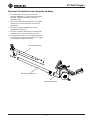
Optional: Attaching a Boom Extension
Boom Assembly
Boom Adapter
1" Rigid Conduit
1. Select a piece of 1” rigid conduit and cut to
length if necessary. Ensure you leave one
threaded end intact.
2. Remove the boom assembly from the
G1 Versi-Tugger. (See p.14 for additional
instructions.)
3. Thread the 1” rigid conduit into the boom
adapter. (A)
4. Insert the boom assembly into the end of the
conduit not threaded into the G1. (B)
5. Use caution while using a conduit boom
extension as the weight of the G1 Versi-Tugger
will increase signicantly.
A.
B.
B.

G1 Versi-Tugger™
Greenlee Tools, Inc. 4455 Boeing Dr. • Rockford, IL 61109-2988 USA • 815-397-7070
18
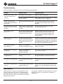
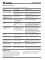
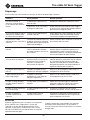
Troubleshooting
If the puller becomes inoperative, refer to the troubleshooting table below.
Problem Probable Cause Probable Remedy
During a pull, the drill, input
shaft AND capstan stop
spinning
Drill battery is low or empty Replace cordless drill battery.
The drill stalled because the pull
force is too high
Stop using the G1 Versi-Tugger and use a larger
cable puller to nish the cable pull.
During a pull, the frame
begins to bend and contacts
the capstan
Force of the pull exceeded 1000
LB.
Do not exceed maximum force of 1000 lb
to avoid cosmetic damage. Unit is still fully
operable.
Drill and input shaft are spin-
ning but the capstan is NOT
spinning
Output shaft key sheared due to
overload from unapproved drill
or motor
Remove output shaft, replace key and
reassemble output shaft.
Drill is slipping off the
input shaft
Drill chuck was tightened down
onto the diameter of the input
shaft and not the three ats
Remove the drill chuck from the input shaft.
Reattach the drill chuck to the input shaft
and ensure that the teeth of the drill chuck
are mating properly with the three ats of
the input shaft.
Capstan wall is not screwing
into the capstan
Misalignment of the threads
can be caused by interference
between the capstan wall and
the anti-backout tab on the
capstan
Realign the threads of the capstan wall knob to
be on axis with the capstan and ensure that the
anti-backout tab on the capstan is inserted into
the radial slots in the capstan wall. Then thread
the capstan wall knob into the capstan.
The handle is spinning
about the frame
Product was dropped or
forcefully swung by the handle
Use a hex key or Allen wrench to tighten the
handle screw down.
The input shaft is sliding off
the gearbox
Product was dropped too
hard or experienced
signicant vibration
Use a hex key or Allen wrench to tighten the
input shaft screw down.
Line breaks during pull when
exiting conduit
Line is rubbing on edge of
conduit
Ensure pulling head is set up so line does not
rub against edge of conduit and uses roller.
Line breaks near pulling head Line is caught between head
and roller
Position line so it runs over the roller, not
beside it.
Line catches or breaks near
capstan
Line is getting caught between
capstan and frame
Position the line to spool around capstan with
tension so as not to slip between capstan and
frame.
Maintenance
Routinely inspect all aspects and components on the
G1 Versi-Tugger to ensure puller is in proper working
order prior to usage. If parts are missing or broken DO
NOT USE and have the puller serviced at an authorized
Greenlee Repair Center.
The gearbox is prelled with high temperature synthetic
lubricant. Therefore, no maintenance is required on
the gearbox.

G1 Versi-Tugger™
Greenlee Tools, Inc. 4455 Boeing Dr. • Rockford, IL 61109-2988 USA • 815-397-7070
19
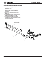
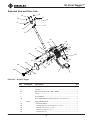
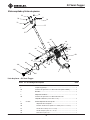
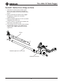
Exploded View and Parts Lists
Parts List – G1 Versi-Tugger
Key Catalog No. Description Qty
1 G1-R12 Drill Strap ................................................................................................1
2 Gearbox............................. .....................................................................1
2A Button Head Cap Screws (M6 x 18MM)............................. ....................3
3 Frame............................. ......................................................................... 1
4 Boom Adapter............................. ............................................................ 1
4A Boom Adapter Button Head Cap Screws (1/4”-20 x 3/4”) .....................4
5 G1-R18 Monopod Adapter Kit............................. ................................................1
5A Monopod Adapter ................................................................................1
5B Quick-Release Pin w/ Lanyard (1/4” x 2-1/4”) .....................................1
5C Shoulder Screw (1/4” x 1-3/8”) ............................................................ 1
5D Wing Screw (#10-32 x 1/2”) ................................................................. 1
5E Locknut (#10-24)............................. ..................................................... 1
7B
7G
7C
7A
7E
8A
4
8D
8C
5B
4A
8B
9A
9F
9C
5C
9B
9E
9D
2A
3
2
6C
6A
6B
5A
5D
5E
9E
9D
1
10A
10C
10B
7F
7H
7D
7G

G1 Versi-Tugger™
Greenlee Tools, Inc. 4455 Boeing Dr. • Rockford, IL 61109-2988 USA • 815-397-7070
20
Parts List – G1 Versi-Tugger (cont'd)
Exploded View and Parts Lists (cont'd)
Key Catalog No. Description Qty
6 G1-R11 Input Shaft Kit ......................................................................................... 1
6A Input Shaft ........................................................................................... 1
6B Key (1/8” x 1/8” x 1/2”)............................. ........................................... 1
6C Set Screw (5/16”-24 x 1/4") ................................................................. 1
7 G1-R14 Boom Assembly Kit................................................................................. 1
7A Puller Head............................. ............................................................. 1
7B Puller Head Sheave .............................................................................. 1
7C Shoulder Screw (1/4" x 2-1/2") ............................................................ 1
7D Locknut (#10-24) .................................................................................. 1
7E Bowtie Cotter Pin (1/16") ..................................................................... 1
7F Clevis Pin (1/4" x 1-1/4") ...................................................................... 1
7G Flange Bushing .................................................................................... 2
7H Quick-Release Pin w/ Lanyard (1/4" x 1-1/16")................................... 1
8 G1-R15 Handle Assembly Kit ............................................................................... 1
8A Handle ................................................................................................. 1
8B Handle Grip .......................................................................................... 1
8C Handle Button Head Cap Screw (1/4” x 7/8”)...................................... 1
8D External Lock Washer (1/4”) ................................................................. 2
9 G1-R16 Capstan Assembly Kit ............................................................................. 1
9A Capstan ................................................................................................ 1
9B Capstan Shaft ...................................................................................... 1
9C Key (3/16” x 3/16” x 1/2”) .................................................................... 1
9D Washer (3/4”) ....................................................................................... 2
9E External Retaining Ring (3/4”) .............................................................. 2
9F Split-Pin (1/4” x 1-3/4”) ........................................................................ 1
10 G1-R13 Capstan Wall Kit ...................................................................................... 1
10A Capstan Wall ........................................................................................ 1
10B Capstan Wall Knob .............................................................................. 1
10C Locknut (3/8”-16) ................................................................................. 1
11 G1-R19 Decal and Warnings Kit (not shown) ....................................................... 1
11A Warning Decal ...................................................................................... 1
11B G1 Capstan Wall Decal ........................................................................ 1
11C G1 Product Info Decal ......................................................................... 1
11D Greenlee Logo Decal ........................................................................... 1
Page is loading ...
Page is loading ...
Page is loading ...
Page is loading ...
Page is loading ...
Page is loading ...
Page is loading ...
Page is loading ...
Page is loading ...
Page is loading ...
Page is loading ...
Page is loading ...
Page is loading ...
Page is loading ...
Page is loading ...
Page is loading ...
Page is loading ...
Page is loading ...
Page is loading ...
Page is loading ...
Page is loading ...
Page is loading ...
Page is loading ...
Page is loading ...
Page is loading ...
Page is loading ...
Page is loading ...
Page is loading ...
Page is loading ...
Page is loading ...
Page is loading ...
Page is loading ...
Page is loading ...
Page is loading ...
Page is loading ...
Page is loading ...
Page is loading ...
Page is loading ...
Page is loading ...
Page is loading ...
Page is loading ...
Page is loading ...
Page is loading ...
Page is loading ...
Page is loading ...
Page is loading ...
Page is loading ...
Page is loading ...
-
 1
1
-
 2
2
-
 3
3
-
 4
4
-
 5
5
-
 6
6
-
 7
7
-
 8
8
-
 9
9
-
 10
10
-
 11
11
-
 12
12
-
 13
13
-
 14
14
-
 15
15
-
 16
16
-
 17
17
-
 18
18
-
 19
19
-
 20
20
-
 21
21
-
 22
22
-
 23
23
-
 24
24
-
 25
25
-
 26
26
-
 27
27
-
 28
28
-
 29
29
-
 30
30
-
 31
31
-
 32
32
-
 33
33
-
 34
34
-
 35
35
-
 36
36
-
 37
37
-
 38
38
-
 39
39
-
 40
40
-
 41
41
-
 42
42
-
 43
43
-
 44
44
-
 45
45
-
 46
46
-
 47
47
-
 48
48
-
 49
49
-
 50
50
-
 51
51
-
 52
52
-
 53
53
-
 54
54
-
 55
55
-
 56
56
-
 57
57
-
 58
58
-
 59
59
-
 60
60
-
 61
61
-
 62
62
-
 63
63
-
 64
64
-
 65
65
-
 66
66
-
 67
67
-
 68
68


Greenlee 52087815 REV 1 - G1 IM.pdf User manual
- Type
- User manual
Ask a question and I''ll find the answer in the document
Finding information in a document is now easier with AI
in other languages
Related papers
-
Greenlee G3 Tugger User manual
-
Greenlee 658 Tray Type Sheave Manual User manual
-
Greenlee Ultra Tugger User manual
-
-
-
-
-
-
-
Other documents
-
 Big Red T32054 User manual
-
Toro Capstan Adaptor, Dingo Compact Utility Loader Installation guide
-
General Pipe Cleaners D-25-2-A Installation guide
-
CHANCE Series 90 Capstan Hoist Owner's manual
-
Milwaukee 49-57-9001 User manual
-
Sharper Image Dream Chair Lounger Owner's manual
-
 Keeper KAC15042 User manual
-
Dynex DX-SW040 User manual
-
 Portable Winch PCA-1213M2ESC Owner's manual
-
Hubbell P308-0880 Owner's manual


