Side-Power SE80/185T IP Installation and User Manual
- Category
- Toys & accessories
- Type
- Installation and User Manual
This manual is also suitable for

Made in Norway
© Sleipner Motor AS version 1.0 - 2007
®
SE80/185T & SE100/185T
Ignition Protected
thruster assembly
SIDE-
POWER
SLEIPNER MOTOR AS
P.O. Box 519
N-1612 Fredrikstad
Norway
Tel: +47 69 30 00 60
Fax: +47 69 30 00 70
Installation and user manual
www.side-power.com
sidepower@sleipner.no
Keep this
manual onboard !

2
SE80/185T & SE100/185T Ignition Protected thruster assembly 1.0 - 2007
Technical specications ............................................................. 2
Planning & important precautions.............................................. 3
Stern thruster installation considerations................................... 3
Bolt on installation .................................................................... 4
Mould on installation ................................................................. 5
Gearhouse and motorbracket .................................................... 6
Oil tank & propellers ................................................................. 7
Electromotor IP assembly .......................................................... 8
Electrical installation ................................................................. 9
Control panel and control-leads............................................... 10
Visual wiring diagram .............................................................. 11
Technical wiring diagram ........................................................ 12
Electrical installation of stern thruster systems ........................12
Checklist .................................................................................. 13
Important user precautions ...................................................... 14
How to use Sidepower thrusters.............................................. 15
Maintenance ............................................................................ 16
Troubleshooting ....................................................................... 17
Warranty statement ................................................................ 18
Parts list ................................................................................... 19
Service centres ....................................................................... 20
Contents
Motor: Custom made reversible DC-motor.
Gearhouse: Seawater resistant bronze. Ballbearing at propellershaft; combination of ballbearing and slide bearing at
driveshaft.
Motor bracket: Seawaterresistant aluminium.
Ignition protection: Conforms to ISO 8846
Propeller: 5 blade skew "Q"-propeller , breglass reinforced composite.
Batteries:
Minimum recommended battery capacity (cold crank capacity by DIN standard)
SE 80/185T 12V : 550 CCA DIN/1045 CCA SAE
SE 80/185T 24V : 300 CCA DIN/570 CCA SAE
SE 100/185T 12V : 750 CCA DIN/1425 CCA SAE
SE 100/185T 24V : 400 CCA DIN/760 CCA SAE
Max. use: S2 = 3 min. or appr. 7-10% within a limited time frame. All electromotors are protected against overheating.
Safety
:
Electronic time-lapse device protects against sudden change of drive direction. Electric thermal cut-off switch in
electromotor protects against over heating (auto reset when electro motor cools down).
Flexible coupling between electro-motor and driveshaft protects electromotor and gearsystem if propeller gets
jammed.
If original Sidepower panel is used, the panel shuts off automatically 6 minutes after last use.
Integrated microprocessor monitors solenoids, reducing wear and risk of solenoid lock-in. Auto-stop of thruster in
case of accidental solenoid lock-in or if run signal is continous for more than 3 minutes.
Technical specications
DECLARATION OF CONFORMITY
We, Sleipner Motor AS
P.O. Box 519
N-1612 Fredrikstad, Norway
declare that this product with accompanying
standard remote control systems complies with the
essential health and safety requirements according
to the Directive 89/336/EEC of 23 May 1989
amended by 92/31/EEC and 93/68/EEC.
2
SP75Ti / SP95Ti ignition protected thruster assembly
1.2.1 - 2007
A
B
W.L.
C
Technical specifications ......................................................... 2
Planning & important precautions ......................................... 3
Stern thruster installation considerations ............................. 3
Bolt on installation .................................................................. 4
Mould on installation ............................................................... 5
Gearhouse and motorbracket ................................................ 6
Oil tank & propellers .............................................................. 7
Electromotor IP assembly ...................................................... 8
Electrical installation ............................................................... 9
Control panel and control-leads .......................................... 10
Visual wiring diagram ........................................................... 11
Technical wiring diagram ..................................................... 12
Electrical installation of stern thruster systems ................... 12
Checklist ............................................................................... 13
Important user precautions .................................................. 14
How to use Sidepower thrusters ......................................... 15
Maintenance .......................................................................... 16
Troubleshooting .................................................................... 17
Warranty statement ............................................................... 18
Parts list ................................................................................ 19
Service centres ...................................................................... 20
Contents
Motor: Custom made reversible DC-motor.
Gearhouse: Seawater resistant bronze. Ballbearing at propellershaft; combination of ballbearing and slide bearing at
driveshaft.
Motor bracket: Seawaterresistant aluminium.
Ignition protection: Conforms to ISO 8846
Propeller: Symmetrical 4 blade kaplan propeller, fibreglass reinforced composite.
Batteries:
Minimum recommended battery capacity (cold crank capacity by DIN standard)
SP 75 Ti IP 12V : 500 CCA DIN / 24V : 250 CCA DIN
SP 95 Ti IP 12V : 700 CCA DIN / 24V : 350 CCA DIN
Max. use: S2 = 3 min. or appr. 7-10% within a limited time frame. All electromotors are protected against overheating.
Safety
:
Electronic time-lapse device protects against sudden change of drive direction. Electric thermal cut-off
switch in electromotor protects against over heating (auto reset when electro motor cools down).
Flexible coupling between electro-motor and driveshaft protects electromotor and gearsystem if propeller
gets jammed.
If original Sidepower panel is used, the panel shuts off automatically 6 minutes after last use.
Integrated microprocessor monitors solenoids, reducing wear and risk of solenoid lock-in. Auto-stop of thruster in
case of accidental solenoid lock-in or if run signal is continous for more than 3 minutes.
Technical specifications
Outside of flange: ECut out in stern: F
Bolt holes dia: G
Bolt position radius: H
60°
D
DECLARATION OF CONFORMITY
We, Sleipner Motor AS
P.O. Box 519
N-1612 Fredrikstad, Norway
declare that this product with accompanying
standard remote control systems complies with the
essential health and safety requirements according
to the Directive 89/336/EEC of 23 May 1989
amended by 92/31/EEC and 93/68/EEC.
Measure
ments ref.
mm / inch
SP75 Ti IP
A299mm / 11,77"
B256mm / 10,08"
C200mm / 7,87"
D337mm / 13,3"
Eø300mm / 11,8"
Fø200mm / 7,84"
G6x ø10,5mm / 0,41"
Hø129mm / 5,08"
Inside
tunnel
dia.
185mm / 7,28"
Max.
stern
thickness
45mm / 1,75"
Motor
output 4,4 KW / 6 HP
Voltage 12 / 24 Volt
SP95 Ti IP
407mm / 16,02"
256mm / 10,08"
200mm / 7,87"
337mm / 13,3"
ø300mm / 11,8"
ø200mm / 7,84"
6x ø10,5mm / 0,41"
ø129mm / 5,08"
185mm / 7,28"
45mm / 1,75"
4,4 KW / 6 HP
12 / 24 Volt
SE 80/185T IP SE 100/185T IP
Optional support (user supplied)

3
SE80/185T & SE100/185T Ignition Protected thruster assembly 1.0 - 2007
Prior to installation, it is important that the installer reads this guide to ensure necessary acquaintance with this product.
The electromotor assembly must be handled carefully. Do not lift it by the internal connections or put it down on the driveshaft.
Beware to keep installation within adviced measurements.
We advice to paint the gearhouse and propellers with antifouling. PS! Do not paint the zinc anodes, sealings or propellershafts.
Do not nish the inside of the tunnel with a layer of gelcoat / topcoat or similiar. It is only room for a thin layer of primer and two layers
of anti-fouling between the tunnel and the props.
With the boat on land, only run the thruster for a fraction of a second, as without resistance it will accelerate very fast to a damaging
rpm. Also, while the thruster is in air, make sure that the propellers have come to a complete stop before performing a direction
change of the thruster, as it does cause damage to the thruster.
This manual is intended to support educated / experienced staff and is therefore not sufcient in all details for the correct installation.
The thruster IP assembly has been tested to be fully ignition protected so that it can be installed in an area with the possibility of
explosive gases in accordance to ISO 8846.
Do not install the thruster in a position where you need to cut a stiffener/stringer/support for the hull integrity without checking with the
boatbuilder that this can be safely done.
When installed in boats approved or classied according to international or special national rules, the installer is responsible for
following the demands in accordance with these regulations / classication rules. The instructions in this guide can not be guaranteed
to comply with all different regulations / classication rules.
NB ! Faulty installation of the tunnel, thruster or panel will render all warranty given by Sleipner Motor AS void.
Planning and important precautions
To achieve maximum effect, reliability and durability from your Sidepower stern thruster, a correct installation is very important.
Please follow the instructions carefully, and make sure that all checkpoints are carefully controlled.
Additional considerations for positioning of the stern thruster
Make sure that the stern-tunnel does not disturb the waterow under the hull
Ensure that when installed the thruster does not foul exisiting equipment inside the boat like steerage links etc.
Make sure that the water ow from the thruster are not intereferred to much by sterndrives, trimtabs etc. as this will reduce the thrust
considerably.
It is possible to mount the tunnel off the boat’s centre line if necessary.
If the stern thickness is to much for the thruster in question you can easily remove hull material in the necessary area to t the
thruster. You only have to reduce the stern thickness down to the max. thickness measurement in the drawing.
Stern thruster installation considerations

4
SE80/185T & SE100/185T Ignition Protected thruster assembly 1.0 - 2007
Fig. 1
Bolt on installation of the stern tunnel
1. Make sure that there are enough space both inside and out-
side the transom of the boat.
2. Once the place for the installation has been decided, hold the
tunnel in place in the horizontal position and mark the bolt
holes. Remove the tunnel and it is then possible to calculate
and mark the centre.
3. It is important that the tunnel ange sits ush on the transom.
If this is not so, then the area on the transom will have to be
attened to ensure a snug t.
PS ! Take care with grinders as it is very easy to remove to
much in breglass
At this time, cut out the centre hole and the transom to the
same internal diameter as the tunnel ange and drill the bolt
holes. Before bolting on the stern tunnel, the prepared area
must be sealed with a gelcoat or similar to ensure there is no
water ingress into the hull.
4. Before tting the tunnel to the transom, t the lower gear leg
to the tunnel as described on page 6. We recommend that
you t the oil feed pipe also before the tunnel is bolted to the
transom.
5. When tting the tunnel, ensure that there is ample sealant
(Sikaex or similar) in the sealing tracks of the tunnel ange
and around the bolts to make a water tight tting (Fig. 1/2).
Bolts, washers and nuts are not included as they will wary de-
pending on the transom thickness We recommend A4 stain-
less with A4 lock nuts and A4 washers of a large diameter on
both outside and inside.
Bolts diameter: ø 10mm or 3/8” stainless steel
6. Refer to the installation manual for the recommended thruster
tting.
If a bow thruster is also installed, we strongly advice to
use separate battery banks for the two thrusters to avoid
extreme voltage drop if both thrusters are to be used at the
same time. Refer to the thruster manuals for adviced battery
capacity and cable sizes for each thruster.
Also ensure that you do not have direct connections of both +
and - if you have built together controls for both thrusters to
avoid current leakage between separate battery banks.
If you are installing the standard Sidepower dual joystick
panel this is already secured.
Fig. 2
SEALANT
WASHERS
LOCKNUT OR
DOUBLE NUTS
SEALANT

5
SE80/185T & SE100/185T Ignition Protected thruster assembly 1.0 - 2007
Boat transom Boat transom
Stern tunnel
Grind off the bolt ange and
the gelcoat both inside and out-
side in the areas shown.
Fig. 1
Mould on installation of the stern tunnel
1. Make sure that there are enough space both inside and out-
side the transom of the boat.
2. Cut of the bolting ange on the stern-tunnel
3. Grind off the gelcoat both inside and outside the remaining
“tube” atleast 10 cm down on the “tube” (Fig. 1).
4. Offer the stern tunnel to the desired position on the transom
and mark around the tube.
5. Cut the marked hole in the transom of the boat.
6. Grind off the gelcoat on the transom of the boat in an area of
atleast 10 cm / 4” around the hole, both outside and inside
(Fig. 1).
7. Offer the stern tunnel to the transom in the desired horizontal
position, then bond to the transom with multi layers matt both
inside and outside (Fig. 2).
Take care not to reduce the internal diameter much, as this
will make it more difcult to mount the thruster
8. Apply gelcoat or similar on all bonded areas.
9. Install the gear leg on the stern-tunnel as described in the
installation manual for the thruster but t the oil feed pipe rst.
10. Basic installation of the motor assembly and electrical installa-
tion are described later in this manual.
Fig. 2
If a bow thruster is also installed, we advice to use seper-
ate battery banks for the two thrusters to avoid extreme
voltage drop if both thrusters were to be used at the same
time. Refer to the thruster manuals for adviced battery
capacity and cable sizes for each thruster.
Also ensure that you do not have direct connections of
both + and - if you have built together controls for both
thrusters to avoid current leakage between seperate bat-
tery banks.
If you are installing the standard Sidepower dual joystick
panel this is already secured.
Bond multiple layers both in-
side and outside

6
SE80/185T & SE100/185T Ignition Protected thruster assembly 1.0 - 2007
1. Try the lower-unit in the tunnel (remove the zinc anodes) rst by using the gasket inside the tunnel. Try on the propellers to make
sure it is centred in the tunnel and turn freely with the same clearance from each blade to the tunnel (Fig. 1).
The gearleg must be tted with the end marked P facing port and the end marked S facing starboard (Fig. 3) for the thrust direction
to correspond with the control panel. If there is no visible P or S marks, t the gearleg with the "SLEIPNER"-casting towards the
stern/back of the boat.
2. Apply a thin layer of sealant on both sides of the gasket (7) and place it carefully on the gearhouse, making sure no sealant gets
into the bolt holes on the gearhouse (Fig 1).
3. Push the gearhouse through the main hole in the tunnel and push the gearhouse and motor-bracket gently together.
4. Fit the enclosed sealing washers to the bolts and screw the lower unit and the motor bracket together with the two provided bolts.
Tighten with 17 Nm / 12,4 lb/ft (Fig. 2).
Fitting gearhouse and motor bracket
Fig. 1
Bolt tightening forces:
Bolts (2x) holding gearhouse to bracket:
17 Nm (12,4 lb/ft)
PORT STARBOARD
S
P
Fig. 3
Fig. 2
22
SP 75 Ti / SP 95 Ti / SP 125 Ti
2.5.1- 2007
Fig. 3
7
1. Die Mittellinie von Tunnel und Boot markieren.
SP 75 Ti / SP 95 Ti: Damit Schubrichtung und Kontrollpanel
über-einstimmen, das Getriebegehäuse so einbauen, daß der
Ver-schluß des Getriebegehäuses (der verschraubte Verschluß
hinter einem der beiden Propeller) Richtung Steuerbord zeigt
(Fig. 5).
SP 125 Ti: Fig. 6
2. Die Löcher mit der Dichtung (7) markieren. Maße überprüfen!
Den Thruster schiffssmittig plazieren (Fig. 1). Da der Abstand
zwischen Propellern und Tunnel wegen größtmöglicher
Performance minimal konstruiert ist, müssen für eine präzise
Installation alle Löcher auf der Tunnelmittellinie liegen.
3. Im Bereich der Motorhalterung darf kein Laminat auf dem
Tunnel sein, da dies zu einem Getriebeschaden führen kann.
Liegt die Motorhalterung nicht eben auf dem Tunnel auf, so
sind sämtliche Unebenheiten in diesem Bereich abzuschleifen.
4. Bohren Sie das Zentrumsloch (ø 32 mm) und dann die
beiden Schraubenlöcher (ø 9 mm).
5. Das Getriebegehäuse mit Getriebeöl EP90 durch die Öffnung
der Ölablaßschraube (4) befüllen. Kupferdichtung (3) einsetzen.
6. Das Getriebegehäuse (ohne Zinkanoden und unteren Teil der
elastischen Kupplung) unter Verwendung der Dichtung in den
Tunnel einpassen. Den Propeller auf die Achse stecken; dieser
muß sich frei bewegen lassen und jedes Propellerblatt muß
den gleichen Abstand zum Tunnel aufweisen. Ist die Tunnel-
innenseite ungleichmäßig, etwas Sikaflex o.ä. auftragen,
damit keine undichte Stelle auftritt.
PS ! Die Durchgänge für das Öl (2) von Dichtmasse freihalten.
7. Etwas Öl oder Fett auf die O-ringe der Motorhalterung geben,
da diese sonst beim Montieren beschädigt werden können.
8. Das Getriebegehäuse durch das Hauptloch im Tunnel führen
und vorsichtig mit der Motorhalterung zusammenschieben.
9. Das Getriebegehäuse und die Motorhalterung mit Hilfe der bei-
den Bolzen verschrauben (Fig. 7).
GEAR OIL
EP 90
3
4
12
Fig. 4
PORT STARBOARD
Bolt tightening forces:
Bolts (2x) holding gearhouse to bracket:
SP 75 Ti / SP 95 Ti: 17 Nm (12,4 lb/ft)
SP 125 Ti: 33 Nm (24 lb/ft)
Getriebe und Motorhalterung
D
Fitting gearhouse and motor bracket
GB
40,0mm
1,57"
Ø 11,00mm
7/16"
TUNNELS
CENTRELINE
BOATS
CENTRELINE
Ø 46,00mm
1,81"
Fig. 1
SP 75 Ti
SP 95 Ti
28,0mm
1,1"
Ø 9mm
0,35"
TUNNELS
CENTRELINE
BOATS
CENTRELINE
Ø 32mm
1,26"
Fig. 2
SP125Ti
PORT STARBOARD
SP
Fig. 5
SP 75 Ti
SP 95 Ti
Fig. 6
SP125Ti
Fig. 7
1. Mark the centreline of the tunnel and the boats centreline. SP75Ti
/SP95Ti: The gearhouse must be fitted with the gearhouse lid (the
screwed in lid behind one of the propellers) on the starboard side of
the boat for the thrust direction to correspond with the control panel
(Fig. 5). SP 125 Ti: Fig. 6
2. Use the gearhouse gasket (7) to mark the centre of the holes and
double check the measurements. Place the thruster in the boats
centreline with the bolt hole as the centre (Fig. 1). It is absolutely
necessary that all holes are in-line with the tunnels’ centreline to
ensure precise installation, as the clearance between the
propellers and the tunnel is minimal to ensure best possible
performance.
3. There must be no casting where the motor bracket is to be placed,
as this will cause possible failure of the gearhouse. The motor
bracket must fit steady on the tunnel, if the tunnel is not smooth,
all bumps or uneven parts must be grinded smooth.
4. Drill the centre-hole ø 32mm and then the two screw-holes ø 9mm.
5. Pre-fill the gearhouse with gear oil type EP90 through the oil drain
screw (4). Make sure to get the copper gasket (3) on again.
6. Try the lower-unit in the tunnel (without the zinc anodes and the
lower part of the flexible coupling) by using the gasket inside the
tunnel. Try on the propellers to make sure they are in the middle of
the tunnel and turn freely with the same clearing from each blade to
the tunnel. Use sealant e.g. Sikaflex to ensure that no leakages
occur.
PS! Make sure that no sealant gets in to the oil-holes (2).
7. Make sure that there is some oil or grease on the O-rings in the
motor bracket before mounting it together with the gearhouse.
8. Push the gearhouse through the main hole in the tunnel and push
the gearhouse and motor-bracket gently together.
9. Screw the lower unit and the motor-bracket together with the two
provided bolts (Fig. 7).
SLEIPNER

7
SE80/185T & SE100/185T Ignition Protected thruster assembly 1.0 - 2007
1. Turn the propeller shaft so that the drivepin (5) is in a horizontal position and ensure that it is centred in the propellershaft.
2. Push the propellers onto the shaft with the track for the drivepin in an horizontal position (same direction as you set the drivepin), all
the way in. There should be almost no gap between the propeller hub and the gearhouse.
3. Place the washer (4) on the prop.shaft and then tighten the lock-nut (3) on the propeller shaft.
4. Place the zinkanode (2) in its designated position and tighten the zincanode holding screw (1). Apply a thread glue (Locktite or
similar) to ensure that the zincanode holding screw does not un-screw itself from the propellers rotation.
Parts description:
1 : Screw for zincanode
2 : Zincanode
3 : Propeller lock nut
4 : Washer
5 : Drivepin for propeller
Fitting propellers
5
3
2
14
Locktite

8
SE80/185T & SE100/185T Ignition Protected thruster assembly 1.0 - 2007
1. Remove the 4 bolts in the motorbracket.
2. Mount the lower part of the exible coupling and tighten the set screws. Insert the "rubber/plastic ring" in this lower part.
3. Place the motor gently on the motorbracket. Be careful, the motor is heavy!
SE80/185T: Ensure that the "rubber/plastic ring" goes into position.
Ensure that you are placing the motor so that the cable terminals on it are available for electric installation later.
4. Fasten the motor to the bracket with the 4 bolts and tigthen them.
5. If you are installing a SE100/185T in an angle of more than 45o off a vertical position, the electromotor needs a separate/
additional support. See illustration in the measurements drawings.
6. Lift the lower part of the exible coupling together with the rubber/plastic ring into the upper exible coupling. The rubber/plastic
ring must be in its correct position in the upper part, fully inserted but not compressed against it (17 mm).
Secure the lower part of the exible coupling in its new position by tightening the set-screws.
NB ! Paint the gearhouse and propeller with antifouling for propellers to prevent growth of barnacles or similar which would reduce the
performance dramatically. Do not paint the propeller shaft, the zincanodes or the end face of the gearhouse.
Fitting the electromotor IP assembly
Final gearleg assembly
Fig. 2
Bolt tightening force (4x):
33 Nm (24 lb/ft)
Bolt tightening force (2x):
17 Nm (12,4 lb/ft)
Fig. 1

9
SE80/185T & SE100/185T Ignition Protected thruster assembly 1.0 - 2007
• Explanation of electrical table
- All cable lengths are the total of + and - (to and from).
- Battery size is stated as minimum cold crank capacity, not Ah.
- Use slow fuse rated to hold stated Amp-Draw for min. 5 minutes.
* Cable size and main battery size when an extra bow battery with minimum the CCA mentioned as A is installed.
• It is important that you use a good cable size and batteries with a high cranking capacity to feed the thruster, because it is the actual
voltage at the motor while running the thruster that decides the output rpm of the motor and thereby the actual thrust. Please see the
list below for advised min. sizes of cables and batteries. You can of course use larger cables for even better results.
• A main switch (*C) that can take the load without noticable voltage drop must be installed in the main positive lead so the power
for the thruster can be turned off independently of the rest of the system when not on board or in emergencies. This should be placed
in an easily accessible place and the boats instructions should include information that this should be turned off like the other main
switches of the boat.
• We also advice to install a fuse (*D) in the positive lead for protection agains short circuiting of the main cables. This fuse should be
of a adequate quality which normally means that it is physically large as these have less voltage drop than the simple / small ones. It
should be of the slow type and sized to take the amperage draw for atleast 5 minutes.
• Remember to use ignition protected fuses and switches if tted in areas that require this feature.
• A circuit breaker can be used instead of the fuse and main power switch as long as the functionality is the same.
• The cable ends must be tted with terminals and these must be well isolated against contact with anything but the proper connection
point.
• If the main switch and fuse are installed in the same gas area they also have to be ignition protected.
• The negative / minus cable connects to the (-) terminal. Bolt M10. Tighten with 25 Nm / 18,43 lb/ft.
• The positive / plus cable connects to the "+" terminal. Bolt M10. Tighten with 25 Nm / 18,43 lb/ft.
Electrical installation
Model Voltage Nominal
current
draw
Min. battery
CCA
>7m total + & - 7-14m total + & - 15-21m total + & - 22-28m total + & - 28-35m total + & - 36-45m total + & -
Min. Rec. Min. Rec. Min. Rec. Min. Rec. Min. Rec. Min. Rec.
SE80/185T 12 V 530 A DIN: 550
SAE:1045
mm2
AWG
60
2/0
70
2/0
95
3/0
2x 70
2x 2/0
2x 70
2x 2/0
2x 95
2x 2/0
2x 95
2x 3/0
270* 2x 120
2x 4/0
340* NA NA
24 V 260 A DIN: 300
SAE: 570
mm2
AWG
25
1
35
1
35
1
50
1/0
60
2/0
70
2/0
70
2/0
95
3/0
95
3/0
120
4/0
120
4/0
2x 95
2x 3/0
SE100/185T 12 V 740 A DIN: 750
SAE: 1425
mm2
AWG
95
3/0
95
3/0
2x 70
2x 2/0
2x 95
2x 3/0
2x 95
2x 3/0
280* 250* 375* NA NA NA NA
24 V 340 A DIN: 400
SAE: 760
mm2
AWG
35
1
50
1/0
50
1/0
70
2/0
60
2/0
95
3/0
95
3/0
120
4/0
120
4/0
2x 95
2x 3/0
2x95
2x 3/0
2x 120
2x 4/0
Minimum and recommended cable dimensions can be identical due to safety margins and cable heat considerations for short cable lenghts.
* Minimum or recommended cable cross section in mm2
Battery & cable recommendations:
9
SP75Ti / SP95Ti ignition protected thruster assembly
1.2.1 - 2007
•Explanation of electrical table
- All cable lengths are the total of + and - (to and from).
- Battery size is stated as minimum cold crank capacity, not Ah.
- Use slow fuse rated to hold stated Amp-Draw for min. 5 minutes.
* Cable size and main battery size when an extra bow battery with minimum the CCA mentioned as A is installed.
•It is important that you use a good cable size and batteries with a high cranking capacity to feed the thruster, because it is the actual
voltage at the motor while running the thruster that decides the output rpm of the motor and thereby the actual thrust. Please see the list
below for advised min. sizes of cables and batteries. You can of course use larger cables for even better results.
•A main switch (*C) that can take the load without noticable voltage drop must be installed in the main positive lead so the power for the
thruster can be turned off independently of the rest of the system when not on board or in emergencies. This should be placed in an easily
accessible place and the boats instructions should include information that this should be turned off like the other main switches of the boat.
•We also advice to install a fuse (*D) in the positive lead for protection agains short circuiting of the main cables. This fuse should be of a
adequate quality which normally means that it is physically large as these have less voltage drop than the simple / small ones. It should
be of the slow type and sized to take the amperage draw for atleast 5 minutes.
•Remember to use ignition protected fuses and switches if fitted in areas that require this feature.
•A circuit breaker can be used instead of the fuse and main power switch as long as the functionality is the same.
•The cable ends must be fitted with terminals and these must be well isolated against contact with anything but the proper connection point.
•If the main switch and fuse are installed in the same gas area they also have to be ignition protected.
•The negative / minus cable connects to the (-) terminal. Bolt M10. Tighten with 25 Nm / 18,43 lb/ft.
•The positive / plus cable connects to the "+" terminal. Bolt M10. Tighten with 25 Nm / 18,43 lb/ft.
Electrical installation
Battery
12V or 24V
+-
*D
*C
Counter Nut
Nut
Washer
Cable terminal
Washer
Counter Nut
Nut
Washer
50 mm2 95 mm2 120 mm2 150 mm2 N / A N / A
O OOO+ OOOO+ 2xOOO
N / A 50 mm2 70 mm2 95 mm2 120 mm2 150 mm2
O OO+ OOO+ OOOO+ 2xOOO
35 mm2 35 mm2 50 mm2 70 mm2 95 mm2 120 mm2
2 2 O OO+ OOO+ OOOO+
70 mm2 105 mm2 150 mm2 175 mm2 N / A N / A
OO+ OOOO 2x OOO 2xOOOO
N / A 70 mm2 95 mm2 120 mm2 150 mm2 180 mm2
OO+ OOO+ OOOO+ 2xOOO 2xOOOO
50 mm2 50 mm2 70 mm2 95 mm2 120 mm2 150 mm2
O O OO+ OOO+ OOOO+ 2xOOO
Table for s election of m ain cable,
battery, fuse and m ain-s witch
s ize s .
up to 7m total + & - 7 - 14m total + & - 14 - 21m total + & - 21 - 28m to tal + & - 28 - 35m total + & - 36 - 45m total + & -
M o de l V oltage Cur r e n t
dr aw
M in. Cable
dim e ns io n
M in.Batte ry
CCA b y DIN
M in. Cable
dim e ns io n
M in. Cable
dim e ns io n
M in. Cable
dim e ns io n
M in.Batte ry
CCA b y Din
M in.Batte ry
CCA b y DIN
M in. Cable
dim e ns io n
M in. Cable
dim e ns io n
M in.Batte r y
CCA b y DIN
M in.Batte r y
CCA b y Din
550 CCA Din
1045 CC A SA E
600 CCA Din
1140 CC A SA E
SP 75 Ti IP
12 V 480 A 550 CCA Din
1045 CCA SA E
24 V 240 A 300 CC A D in
570 CCA SA E
12V
Extr .batt * 300 A 300 CC A D in
570 C C A SA E
300 CC A D in
570 C C A SA E
350 CCA Din
665 CC A SA E
350 CCA Din
665 CC A SA E
350 CCA Din
665 CC A SA E
550 CCA Din
1045 CC A SA E
300 CC A D in
570 C C A SA E
300 CC A D in
570 C C A SA E
350 CCA Din
665 CC A SA E
350 CCA Din
665 CC A SA E
750 CCA Din
1425 CC A SA E
750 CCA Din
1425 CC A SA E
750 CCA Din
1425 CC A SA E
SP 95 Ti IP
12 V 680 A 750 CCA Din
1425 CCA SA E
12V
Extr .batt * 400 A 350 CC A D in
665 C C A SA E
24 V 340 A 400 CC A D in
760 CCA SA E
400 CC A D in
760 C C A SA E
M in.Batte r y
CCA b y Din
400 CC A D in
760 C C A SA E
400 CCA Din
760 CC A SA E
450 CCA Din
855 CC A SA E
450 CCA Din
855 CC A SA E
350 CC A D in
665 C C A SA E
350 CCA Din
665 CC A SA E
350 CCA Din
665 CC A SA E
350 CCA Din
665 CC A SA E
350 CCA Din
665 CC A SA E
9
SE 60/185S ignition protected thruster assembly 1.0 - 2007
• Explanation of electrical table
- All cable lengths are the total of + and - (to and from).
- Battery size is stated as minimum cold crank capacity, not Ah.
- Use slow fuse rated to hold stated Amp-Draw for min. 5 minutes.
* Cable size and main battery size when an extra bow battery with minimum the CCA mentioned as A is installed.
• It is important that you use a good cable size and batteries with a high cranking capacity to feed the thruster, because it is the actual
voltage at the motor while running the thruster that decides the output rpm of the motor and thereby the actual thrust. Please see the
list below for advised min. sizes of cables and batteries. You can of course use larger cables for even better results.
• A main switch (*C) that can take the load without noticable voltage drop must be installed in the main positive lead so the power
for the thruster can be turned off independently of the rest of the system when not on board or in emergencies. This should be placed
in an easily accessible place and the boats instructions should include information that this should be turned off like the other main
switches of the boat.
• We also advice to install a fuse (*D) in the positive lead for protection agains short circuiting of the main cables. This fuse should be
of a adequate quality which normally means that it is physically large as these have less voltage drop than the simple / small ones. It
should be of the slow type and sized to take the amperage draw for atleast 5 minutes.
• Remember to use ignition protected fuses and switches if tted in areas that require this feature.
• A circuit breaker can be used instead of the fuse and main power switch as long as the functionality is the same.
• The cable ends must be tted with terminals and these must be well isolated against contact with anything but the proper connection
point.
• If the main switch and fuse are installed in the same gas area they also have to be ignition protected.
• The negative / minus cable connects to the (-) terminal. Bolt M10. Tighten with 25 Nm / 18,43 lb/ft.
• The positive / plus cable connects to the "+" terminal. Bolt M10. Tighten with 25 Nm / 18,43 lb/ft.
Electrical installation
Model Voltage Nominal
current
draw
Min. battery
CCA
>7m total + & - 7-14m total + & - 15-21m total + & - 22-28m total + & - 28-35m total + & - 36-45m total + & -
Min. Rec. Min. Rec. Min. Rec. Min. Rec. Min. Rec. Min. Rec.
SE60/185S 12 V 340 A DIN: 350
SAE:665
mm2
AWG
35
1
50
1/0
60
2/0
95
3/0
95
3/0
2x 70
2x 2/0
120
4/0
2x95
2x 3/0
2x 95
2x 3/0
2x120
2x 4/0
2x120
2x 4/0
280*
24 V 170 A DIN: 175
SAE: 332
mm2
AWG
25
1
35
1
25
1
35
1
25
1
35
1
35
1
50
1/0
50
1/0
60
2/0
60
2/0
70
2/0
Battery & cable recommendations:
Minimum and recommended cable dimensions can be identical due to safety margins and cable heat considerations for short cable lenghts.
* Minimum or recommended cable cross section in mm2
9
SP55S2i ignition protected thruster assembly
1.1 - 2006
•Explanation of electrical table
- All cable lengths are the total of + and - (to and from).
- Battery size is stated as minimum cold crank capacity, not Ah.
- Use slow fuse rated to hold stated Amp-Draw for min. 5 minutes.
* Cable size and main battery size when an extra bow battery with minimum the CCA mentioned as A is installed.
•It is important that you use a good cable size and batteries with a high cranking capacity to feed the thruster, because it is the actual
voltage at the motor while running the thruster that decides the output rpm of the motor and thereby the actual thrust. Please see the list
below for advised min. sizes of cables and batteries. You can of course use larger cables for even better results.
•A main switch (*C) that can take the load without noticable voltage drop must be installed in the main positive lead so the power for the
thruster can be turned off independently of the rest of the system when not on board or in emergencies. This should be placed in an easily
accessible place and the boats instructions should include information that this should be turned off like the other main switches of the boat.
•We also advice to install a fuse (*D) in the positive lead for protection agains short circuiting of the main cables. This fuse should be of a
adequate quality which normally means that it is physically large as these have less voltage drop than the simple / small ones. It should
be of the slow type and sized to take the amperage draw for atleast 5 minutes.
•Remember to use ignition protected fuses and switches if fitted in areas that require this feature.
•A circuit breaker can be used instead of the fuse and main power switch as long as the functionality is the same.
•The cable ends must be fitted with terminals and these must be well isolated against contact with anything but the proper connection point.
•If the main switch and fuse are installed in the same gas area they also have to be ignition protected.
•The negative / minus cable connects to the (-) terminal. Bolt M10. Tighten with 25 Nm / 18,43 lb/ft.
•The positive / plus cable connects to the "+" terminal. Bolt M10. Tighten with 25 Nm / 18,43 lb/ft.
Electrical installation
Battery
12V or 24V
+-
*D
*C
Counter Nut
Nut
Washer
Cable terminal
Washer
Counter Nut
Nut
Washer
35 mm2 60 mm2 95 mm2 95 mm2 120 mm2 120 mm2
AWG 1 AWG OO AWG OOO AWG OOOO AWG OOOO 2 x AWG OOOO
25 mm2 25 mm2 35 mm2 35 mm2 50 mm2 50 mm2
AWG 4 AWG 4 AWG 2 AWG 2 AWG 1 AWG 1
Min.Batte ry
CCA by Din
200 CCA Din
380 CCA SAE
200 CCA Din
380 CCA SAE
200 CCA Din
380 CCA SAE
250 CCA Din
475 CCA SAE
200 CCA Din
380 CCA SA E
400 CCA Din
760 CCA SAE
350 CCA Din
665 CCA SAE
Min.Battery
CCA by Din
12 V 330 A Din
627 A SAE
350 CCA Din
665 CCA SAE
24 V 160 A Din
304 A SAE
200 CCA Din
380 CCA SAE
SP55S2i
IP
Min. Cable
dim e ns ion
Min.Battery
CCA by Din
350 CCA Din
665 CCA SAE
400 CCA Din
760 CCA SAE
400 CCA Din
760 CCA SA E
Min.Batte ry
CCA by DIN
Min. Cable
dim e ns ion
Min. Cable
dim e ns ion
Min.Battery
CCA by DIN
16 - 19m total + & - 20 - 23m total + & - 24 - 27m total + & -
Model Voltage Curre nt
draw
Min. Cable
dim e ns ion
Min.Battery
CCA by DIN
Min. Cable
dim e ns ion
Min. Cable
dim e ns ion
Table for selection of main cable,
battery, fuse and main-switch
sizes.
up to 7m total + & - 8 - 11m total + & - 12 - 15m total + & -
RED:
+
BLACK: -

10
SE80/185T & SE100/185T Ignition Protected thruster assembly 1.0 - 2007
• You can install as many panels as you wish by using optional Y-connectors. If two or more panels are operated at the same time in
opposite directions, the electronic controlbox will stop the thruster until it only receives a signal to go in one direction.
• When using original Sidepower equipment it is all "plug & go".
• If the drive direction of the thruster is the opposite of what ex-pected, the blue and grey wire must be changed on each panel.
• The mechanical installation of the panel is described in the manual following the panel.
• The IP thruster is gas proof based on the control panel lead ending outside of the area that requires ignition protection. The pretted
control lead must be tted in the boat so there is no risk of damage to the insulation, causing explosive gas penetration.
• The thruster control should be placed in a position were it is easy to use, and it is very common to use the thruster at the same time
as your gear / throttle lever so it is normally a user friendly solution to be able to access these with one hand for each control.
Pin conguration of 4 pole AMP contact:
Pin1: BLACK = Ground
Pin2: BLUE = Engages thruster SB solenoid
Pin3: GREY = Engages thruster Port solenoid
Pin4: RED = Positive voltage for control panel
Control panel and control-leads
10
SP75Ti / SP95Ti ignition protected thruster assembly
1.2.1 - 2007
•You can install as many panels as you wish by using optional Y-connectors. If two or more panels are operated at the same time in
opposite directions, the electronic controlbox will stop the thruster until it only receives a signal to go in one direction.
•When using original Sidepower equipment it is all "plug & go".
•If the drive direction of the thruster is the opposite of what ex-pected, the blue and grey wire must be changed on each panel.
•The mechanical installation of the panel is described in the manual following the panel.
•The IP thruster is gas proof based on the control panel lead ending outside of the area that requires ignition protection. The prefitted
control lead must be fitted in the boat so there is no risk of damage to the insulation, causing explosive gas penetration.
•The thruster control should be placed in a position were it is easy to use, and it is very common to use the thruster at the same time as
your gear / throttle lever so it is normally a user friendly solution to be able to access these with one hand for each control.
Pin configuration of 4 pole AMP contact:
Pin1: BLACK = Ground
Pin2: BLUE = Engages thruster SB solenoid
Pin3: GREY = Engages thruster Port solenoid
Pin4: RED = Positive voltage for control panel
Control panel and control-leads
1 2
34
21
34
Pin configuration in contacts
SLEIPNER
SIDEPOWER
THRUSTER
OFFON ON
SLEIPNER
SIDEPOWER
THRUSTER
OFFON ON

11
SE80/185T & SE100/185T Ignition Protected thruster assembly 1.0 - 2007
11
SP75Ti / SP95Ti ignition protected thruster assembly
1.2.1 - 2007
"Visual" wiring diagram
A2A1
Fuse
9681245
red
grey
blue
black
grey
blue
brown
red
6 1230i
Electronic
control box
Thermal
switch
Battery
12V
or
24V
Battery
main
switch
M
4
3
2
1
3
red
red
black
7
white

12
SE80/185T & SE100/185T Ignition Protected thruster assembly 1.0 - 2007
12
SP75Ti / SP95Ti ignition protected thruster assembly
1.2.1 - 2007
SLEIPNER
SIDEPOWER
THRUSTERS
OFF
ON ON
BOW
STERN
To sternthruster
To bowthruster
grey
blue
black
grey
blue
red
ON / OFF
System
Control
light
Joystick
for stern-
thruster
Joystick
for bow-
thruster
Positive lead from
sternthruster have been
removed in panel to
avoid current leakage
between different
battery banks if the
thrusters are powered
by different battery
banks.
Wiring diagram (simplified) for dual joystick panel
Visual connection diagram for dual joystick panel
yWe advice to use different battery banks for each thruster to ensure
maximum performance when both are used at the same time.
yWhen using the original Sidepower control cables just connect them
to the corresponding joystick
yThere are no plus/positive power connected from the bowthruster
yellow
BOWSTERN
black
Technical wiring diagram
Electrical installation of stern thruster systems
M
Thermal
switch
Electronic
interface box
6 1230i
A2
A1
4 pin
AMP
connector
On Motor
4
2
1
3
Fuse Battery
main
switch
1
5
4
2
6
8
9red (+)
grey
(sig +)
blue
(sig +)
black (-)
red
grey
(sig -)
blue
(sig -)
brown
3red
Fused
inside 1A
black
7
white

13
SE80/185T & SE100/185T Ignition Protected thruster assembly 1.0 - 2007
Propeller is fastened correctly to the shaft.
Propeller turns freely in tunnel.
The zinc-anode holding screw is tightened well with thread glue.
There is a sturdy additional support under the electric motor, taking the weight load of the electromotor assembly away
from the stern tunnel.
All electrical wiring, cable sizes and battery capacity is according to the thruster installation manual.
All bolts are securely tightened and sealant are applied as instructed.
Anti-fouling have been applied to the gearhouse and propeller but NOT on the zincanode or the gearhouse lid where the
propeller is fastened.
Correct drive direction as per controlpanel.
All electrical connections are clean, dry and tight, and the correct cable, fuse and main switch sizes have been used.
The bolts holding the gearhouse and motorbracket together are tightened correctly.
Very important for IP protection:
The main power cables have securely been connected as described.
The control lead ends out of the explosive area and has been properly tted and secured against damage.
The thruster has been installed as per the instructions in this manual and all points in checklist above have been controlled.
Signed: ..................................... Date: .......................................
Extra pre-delivery tests by installer / yard who does not use other quality control systems !
Thruster type: ................................................. Voltage: ......................
Serial number: .....................................................................................
Date of delivery: ..................................................................................
Correct drive direction as per controlpanel: .......................................
Voltage at thruster when running: ......................................................
Battery cable size used: .....................................................................
Other comments by installer:
Checklist

14
SE80/185T & SE100/185T Ignition Protected thruster assembly 1.0 - 2007
Ensure that you know the location and how to operate the main battery switch and that disonnects the thruster from all power sources
(batteries) so that the thruster can be turned off in case of a malfunction.
Always turn the main power switch off before touching any part of the thruster, as an incidental start while touching moving parts can
cause serious injuries.
Always turn the control device off when the thruster is not in use.
The maximum continous usage time of the electrical thruster is approximately 3 minutes. The electromotor has a built in thermal cut-off
switch that will shut off the electromotor if it is overheating and re-engage it when it has cooled down some. This should be considered
when planning your manouvering.
This also means that the thruster will limit its total running time per time period so that you can not count on the thruster to hold you
in a current and sidewind for extensive time periods. Depending on the ambient temperatures etc. the thruster will be able to run ap-
proximately 10 % of the time.
Never use a thruster close to somebody in the water, as the thruster will draw objects close by into the tunnel and contact with the
rotating propellers will cause serious injuries.
With the boat on land, only run the thruster for a fraction of a second, as without resistance it will accelerate very fast to a damaging
rpm. Also, while the thruster is in air, make sure that the propellers have come to a complete stop before performing a direction change
of the thruster, as it might cause damage to the thruster.
If the thruster stops giving thrust while the electromotor is running, chances are that there is a problem in the drive-system. You must
then immediately stop trying to run it, and turn it off, as running the electromotor for more than a few seconds without resistance from
the propeller, can cause serious damage to the electromotor.
When leaving the boat always turn off the main power switch for the thruster.
We advice to always keep the main engine(s) running while using a thruster. This will keep the batteries in a good charge condition.
This will also give better performance to the thruster, as a higher voltage at the thruster results in a higher torque (power) in the elec-
tromotor.
Please note that the performance of a thruster strongly depends on the voltage available at the electromotor. This voltage will decrease
by time because aging batteries have a reduction of capacity. By installing new batteries the effect of the thruster should be back at
the original level.
Make sure that only one control is used at the same time, if two panels are operated in opposite directions at the same time the thruster
will not run at all. If they are operated in the same direction the thruster will run in this direction.
If the thruster is not performing or functioning as usual, the cause for this must be found and corrected as soon as possible so to
avoid causing any other or further dammage to the equipment. You must also turn off the main battery switch immediately in case the
problem is of electric origin.
To activate the docking control panel, push the two “ON” buttons simultaneously.
The docking control panel shuts of automatically approx. 25 minutes after it was energized. To use the docking control panel later, push
the two “ON” buttons simultaneously.
The boat switch is an on/off switch device only that controls your thruster(s). The thruster(s) will run at a constant speed regardless of
how hard you pull/push the control switch.
Warning:
Tampering with the Ignition Protected stern thruster assembly or any attempt to disassemble anything on this thruster ass-
mebly inside the boat can cause an explosion with very serious consequences.
If there is a problem with your Ignition Protected stern thruster, please contact your dealer.
Danger: NEVER Disassemble any part of the Ignition Protected stern thruster assembly
Important user precautions

15
SE80/185T & SE100/185T Ignition Protected thruster assembly 1.0 - 2007
How to use a bowthruster
1. Turn main power switch for the bowthruster on. (Always turn off the main power switch when not onboard.)
2. Please take some time to exercise thruster usage in open water to avoid damages to your boat.
3. Turn the controlpanel on by pushing both "ON" buttons on the original Sidepower panel simultaneously. If another type of control is
installed, engage the On/Off switch for the bowthruster.
4. Turn the bow in the desired direction by pushing the red button for port movement or the green button for starboard movement. If you
have a joystick control, move it in the direction you wish the bow to move. Other controls like footswitches or toggle-switches on the
throttle can be used. These are normally logically installed, so by engaging the port control, the bow goes port etc. In case of any
doubts, try in open waters rst.
5. Depending on the sideways speed of the bow, you must disen-gage the control device shortly before the bow is in the desired direc-
tion, as the boat will continue to move after stopping the bowthruster.
How to use a single stern thruster
Some boats might however have installed a single stern thruster because of space limitation in the bow. In this case the stern
thruster is used in the same way as a single bow thruster (see above) for moving the boat's stern.
How to use a bow and stern thruster combined
The combination of a bow and stern thruster offers total manouverability to the boat and the opportunity to move the bow and the
stern separately from each other. This enables you to move the boat sideways in both directions and to turn the boat around it's
own axis staying at the same place.
• Again, if in doubt, try in open water rst!
How to use Sidepower thrusters
15
SP75Ti / SP95Ti ignition protected thruster assembly
1.2.1 - 2007
How to use a bowthruster
1. Turn main power switch for the bowthruster on. (Always turn off the main power switch when not onboard.)
2. Please take some time to exercise thruster usage in open water to avoid damages to your boat.
3. Turn the controlpanel on by pushing both "ON" buttons on the original Sidepower panel simultaneously. If another type of control is
installed, engage the On/Off switch for the bowthruster.
4. Turn the bow in the desired direction by pushing the red button for port movement or the green button for starboard movement. If you
have a joystick control, move it in the direction you wish the bow to move. Other controls like footswitches or toggle-switches on the
throttle can be used. These are normally logically installed, so by engaging the port control, the bow goes port etc. In case of any
doubts, try in open waters first.
5. Depending on the sideways speed of the bow, you must disen-gage the control device shortly before the bow is in the desired
direction, as the boat will continue to move after stopping the bowthruster.
How to use a single stern thruster
Some boats might however have installed a single stern thruster because of space limitation in the bow. In this case the stern
thruster is used in the same way as a single bow thruster (see above) for moving the boat's stern.
How to use a bow and stern thruster combined
The combination of a bow and stern thruster offers total manouverability to the boat and the opportunity to move the bow and the
stern separately from each other. This enables you to move the boat sideways in both directions and to turn the boat around it's own
axis staying at the same place.
•Again, if in doubt, try in open water first!
Turn boat to port
Turn boat to starboardTo turn panel OFF
To turn panel ON
Bow+Stern
Thruster
How to use Sidepower thrusters

16
SE80/185T & SE100/185T Ignition Protected thruster assembly 1.0 - 2007
» Keep the propeller and gearhouse clean from growth by painting with antifouling before every season.
PS ! The zinc anode, sealing and propeller shafts must abso-lutely not be painted. Be careful that you don't ll paint in the
"tracks" in the gearhouse that the propeller hub moves in.
» Change the zinc anode before every season, or when about half the anode is gone. Always use a sealant on the screw holding
the zincanode to ensure that it does not fall off. Please observe that in some waterconditions it can be necessary to install an extra
zincanode to ensure that it lasts for the whole period between regular service lifts of the boat. Consult your dealer for information on
how to do this.
» As a part of the seasonal service of your boat, and before every season, always check that:
• The propeller is securely fastened
• The bolts holding the electric motor to the motorbracket are fastened correctly.
• The area where the thruster is installed is clean and dry. If there are signs of water you must try to nd the source and eliminate it.
• All electrical connections are clean and fastened rmly.
• Make sure that your batteries are in a good condition so that the thruster gets a good voltage. Old or bad batteries will give a re-
duced performance from the thruster.
Maintenance
Warning:
Tampering with the Ignition Protected stern thruster assembly or any attempt to disassemble anything on this thruster ass-
mebly inside the boat can cause an explosion with very serious consequences.
If there is a problem with your Ignition Protected stern thruster, please contact your dealer.
Danger: NEVER Disassemble any part of the Ignition Protected stern thruster assembly
5
32
1
4
Locktite
Power & control cables
Ignition protected casing
Motorbracket for holding motor and
gearhouse together on the tunnel.
Flexible coupling secures the electromo-
tor if propeller is jammed. Changeable
from inside the boat.
5-blade skew Q-PROP propeller for
ultimate performance.
Prelled &sealed gearleg.
Changeable zincanode protects gear-
house from corrosion in seawater.
Fastening screw for zincanode
Zincanode
Propeller lock nut
Washer
Drivepin for propeller
7
4
5
6
1
3
2
4
5
1
3
2
1
7
34
6
5
3
2
14
Locktite
5
2

17
SE80/185T & SE100/185T Ignition Protected thruster assembly 1.0 - 2007
Before seeking assistance at the help desk of your Sidepower dealer / distributor please perform these tests and make notes of all mea-
surements to ensure that they have as much information as possible to work on.
NB! All check points and solutions must be carried out after consulting the relevant information elsewhere in this manual to under-stand how
the system is intended to work. If you are unable to understand what to check, you must consult a professional.
Trouble shooting
Solution
Check the exible coupling and the motor installation to ensure correct con-
nection of the exible coupling before re-tting the electromotor
Re-fasten or replace the propeller and/or key.
In case of a failure inside the gearhouse, we advice to get a replacement gear-
house instead of attempting to repear the internal gear and bearing system.
If wrong, contact your dealer or distributor to obtain parts with the correct voltage.
The no load voltage should be:
12V system =12,7V / 24V system = 25,4 V. If below 12,3V / 24,6V your bat-
teries are not in a good charge state or worn out and must be recharged or
replaced before trying to run the thruster.
If less than 8,5V at the thruster the voltage is to low for the thruster to operate cor-
rectly. In a 24V boat the thruster will operate down to approx. 12V, but the perfor-
mance will be very bad. Find and correct the reason for this low voltage which will
probably be one or more of these points: main battery cable sizes and connec-
tions, battery size and condition, fuse and main power switch performance.
If the thruster runs in both directions, try the same in the connector that goes
into the back of the control panel. If it also works in this position, check the
contact and wires on the back of the panel and try to engage this again by
pushing both ON buttons simultaneously. If the panel does not turn on (see
control light), measure the voltage between the Red and the Black in the con-
tact going into the thruster. If the voltage is good, chances are that the panel
is not working.
If it works by the thruster, and not by the panel there is a bad contact or a
broken lead the controlcables between these two test points.
Measure that you have the correct voltage between the Red (+) and all the
other colours in the contact. If you do not get a reading.
Between main minus (A1 on motor) and the blue and the grey wire connec-
ted to the sides of the main solenoids you should have the same voltage as
between the main battery cables on the thruster.
If not, check that the internal wiring on the solenoid is ok and measure that
there is contact through the magnetising spools of each side of the solenoid
(measure between the red and blue on one side, and red and grey on the
other side with an Ohm meter.). If there are no contact between these, the
solenoid is broken and needs replacing.
If less than 10,5 V / 21V the thruster will not perform at specied effect.
If one or more brushes are loose/has no tension from the brush-spring, the
performance will be low.
If there are growth in the tunnel, this will disturb / block the waterow and
especially barnacles on the propeller will greatly reduce performance.
Re-charge battery(ies), if this is not sufcient, replace battery(ies).
Check for bad cable connections, if necessary tighten/re-adjust connections.
Check cable size in accordance to manual.
Shut off thruster main switch, tap slightly on the solenoid to see if it will rele-
ase. Turn on thruster main switch. If solenoid is still in lock-in mode, replace
solenoid.
Check
If the exible coupling between the motor and dri-
veshaft is not tted correct inside the boat
Are the propellers in the tunnel fastened correctly
on the prop-shaft (key present)
With the motor removed, turn the driveshaft from
inside the boat to feel if the gears are engaging and
turning the prop-shaft.
Check that the voltage of the electromotor are cor-
rect for your installation by their labels.
Check the voltage at the thruster between main minus
input (A1 on motor) and main plus input point:
Check the voltage at the thruster while you are try-
ing to run it. Keep main engine(s) running to have
continous charge to the batteries.
If the main solenoids on the thruster are not even
trying to engage (clicking) they are probably not
getting a "run" signal from the control system. Try
to run the thruster without the panel by directly con-
necting the red and the blue or the red and the grey
wires in the controlcable contact coming from the
thruster.
If the thruster does not run at all, or only in one direction
in the above tests, check the internal wiring on the
thruster motor, solenoids and electronic motor inter-
face box to be in accordance with the wiring diagram
and ensure that all connections are clean and tight.
Check voltage at thruster when running
Check that all the brush-springs sits correctly on the
brushes in the electromotor.
Check that the propeller, gearhouse and tunnel is
free from growth / barnacles etc.
Solenoid apping, most probable cause: low
voltage.
Solenoid lock-in, auto stop of thruster, auto retry
every 10 seconds.
» The electromotor runs, but there is no thrust.
» The thruster does not start at all or works only in one direction.
» The thruster has an unexpected low performance.
» The thruster runs for approximately 0,5 seconds every 4 seconds.
» The thruster runs for approximately 0,5 seconds every 10 seconds.

18
SE80/185T & SE100/185T Ignition Protected thruster assembly 1.0 - 2007
1. The equipment manufactured by Sleipner Motor AS (The “Warrantor”) is warranted to be free from defects in workmanship and mate-
rials under normal use and service.
2. This Warranty is in effect for of two years from the date of purchase by the user. Proof of purchase must be included, to establish that
it is inside the warranty period.
3. This Warranty is transferrable and covers the product for the specied time period.
4. In case any part of the equipment proves to be defective, other than those parts excluded in paragraph 5 below, the owner should do
the following:
(a) prepare a detailed written statement of the nature and circumstances of the defect, to the best of the Owner's knowledge, in-
cluding the date of purchase, the place of purchase, the name and address of the installer, and the Purchaser’s name, adress and
telephone number;
(b) the Owner should return the defective part or unit along with the statement referenced in the preceding paragraph to the warran-
tor, Sleipner Motor AS or an authorized Service Centre, postage/shipping prepaid and at the expense of the Purchaser;
(c) if upon the Warrantor’s or Authorized Service Centre’s examination, the defect is determined to result from defective material or
workmanship, the equipment will be repaired or replaced at the Warrantor’s option without charge, and returned to the Purchaser at
the Warrantor’s expense;
(d) no refund of the purchase price will be granted to the Purchaser, unless the Warrantor is unable to remedy the defect after having
a reasonable number of opportunities to do so. Prior to refund of the purchase price, Purchaser must submit a statement in writing
from a professional boating equipment supplier that the installation instructions of the Installation and Operation Manual have been
complied with and that the defect remains;
(e) warranty service shall be performed only by the Warrantor, or an authorized Service Centre, and any attempt to remedy the defect
by anyone else shall render this warranty void.
5. There shall be no warranty for defects or damages caused by faulty installation or hook-up, abuse or misuse of the equipment includ-
ing exposure to excessive heat, salt or fresh water spray, or water immersion except for equipment specically designed as water-
proof.
6. No other express warranty is hereby given and there are no warranties which extend beyond those described in section 4 above.
This Warranty is expressly in lieu of any other expressed or implied warranties, including any implied warranty of merchantability,
tness for the ordinary purposes for which such goods are used, or tness for a particular purpose, and any other obligations on the
part of the Warrantor or its employees and representatives.
7. There shall be no responsibility or liability whatsoever on the part of the Warrantor or its employees and representatives for injury to
any person or persons, or damage to property, loss of income or prot, or any other consequential or resulting damage or cost which
may be claimed to have been incurred through the use or sale of the equipment, including any possible failure or malfunction of the
equipment, or part thereof.
8. The Warrantor assumes no liability for incidental or consequential damages of any kind including damages arising from collision with
other vessels or objects.
9. This warranty gives you specic legal rights, and you may also have other rights which vary from country to country.
Warranty statement

19
SE80/185T & SE100/185T Ignition Protected thruster assembly 1.0 - 2007
SE80/185T IP & SE100/185T IP
50
SP 75 Ti / SP 95 Ti / SP 125 Ti
2.5.1- 2007
SP 75 Ti
15
17
18
16
2223 212425262829
20 19
27
30
13
14
11 7
8
621
2
1
3
45
9
10
12
8
11
Ref: 12V 24V
30. Complete electric motor assem bly 6 0101 12 6 0101 24
29. Nut for solenoid cover 6 8810 6 8810
28. Solenoid cover 6 2025 6 2025
27. Complete solenoid kit 6 0131 12 6 0131 24
26. Solenoid 41371123 41371243
25. Internal w iring loom 6 1226B 6 1226B
24. Electronic control box 6 1232i 6 1232i
23. Solenoid bracket kit 6 0135 6 0135
22. Key for electric motor shaft 10 1440 10 1440
21. Electric motor N/A N/A
20. Brush springs for electric motor (kit) 6 0170 12* 6 0170 24*
19. Brushes for electric motor (kit) 6 0180 12* 6 0180 24*
18. Complete flexible coupling 7 1450 7 1450
17. Rubber element 7 1451 7 1451
16. Oil container w ith holder 20 0300 20 0300
15. Oil hose w ith hose clamps 20 0400 20 0400
14. Complete m otor bracket 8 0500 8 0500
13. O-ring seals in motor bracket 7 1340 7 1340
12. Complete gearleg 8 0600 8 0600
11. Gearleg bolt 7 1080 7 1080
10. Drive shaft seal 7 1350 7 1350
9. Drive shaft key 6 1440 6 1440
8. Propeller shaft seal 6 1350 6 1350
7. Gasket 8 0610 8 0610
6. Oil drain screw w ith gasket 6 1220 6 1220
5. Zinc anode 7 1190 7 1190
4. Locknut 4 1260 4 1260
3. Propeller w asher 7 1181 7 1181
2. Propeller drive pin 6 1241 6 1241
1. Propeller 7 1260 7 1260
*
Other comments:
Please provide thruster serial number
w hen ordering brushes and brush springs.
Part #
Original model
Model period
SP 75 Ti
12/04 <
12V 24VRef:
Part #
SE 80/185T
09/07 <
Original model
Model period
12V 24V
Part #
SE 100/185T
09/07 <
9
18
1 2345 2 1 3 4 5
6
7
88
10
11 12
13 13
12
14
16
17
15
19
20
20 Complete IP electric motor
assembly
6 0101 12 6 0101 24 8 0101 12 8 0101 24
19 Key for eletric motor shaft 10 1440 10 1440 10 1440 10 1440
18 Complete exible coupling 7 1462 7 1462 N/A N/A
17 Coupling, engine side N/A N/A 7 1456
16 Rubber element N/A N/A 7 1458
15 Coupling, gearleg side N/A N/A 7 1457
14 Complete motor bracket 8 0501 8 0501 N/A N/A
13 Bolt, motor to ange N/A N/A 101360 101360
12 Bolt, ange to bracket N/A N/A 11031 11031
11 Flange N/A N/A 921302 921302
10 Bracket N/A N/A 8 0501 8 0501
9Complete gearleg 8 0601 8 0601 8 0601 8 0601
8 Gearleg bolt 7 1080 7 1080 7 1080 7 1080
7 Driveshaft key 6 1440 6 1440 6 1440 6 1440
6 Gasket 8 0610 8 0610 8 0610 8 0610
5 Zink anode 7 1190 7 1190 7 1190 7 1190
4 Locknut 4 1260 4 1260 4 1260 4 1260
3 Propeller washer 7 1181 7 1181 7 1181 7 1181
2 Propeller drivepin 6 1241 6 1241 6 1241 6 1241
1 Propeller 7 1261 7 1261 7 1261 7 1261

Argentina
Trimer SA
Buenos Aires
Tel: +54 11 4580 0444
Fax: +54 11 4580 0440
www.trimer.com.ar
trimer@trimer.com.ar
Australia
AMI Sales
Freemantle, WA
Tel: +61 89 331 0000
Fax: +61 89 314 2929
Austria
G. Ascherl GmbH
Hard, Bregenz
Tel: +43 5574 899000
Fax: +43 5574 89900-10
www.ascherl.at
Benelux
ASA Boot Electro
Watergang
Tel: +31 20 436 9100
Fax: +31 20 436 9109
www.asabootelectro .nl
Brazil
Electra Service Ltda.
Guaruja
Tel: +55 13 3354 3599
Fax: +55 13 3354 3471
www.electraservice.br.com
Bulgaria
Yachting BG
Burgas
tel: +359 56 919090
fax: +359 56 919091
www.yachting.bg
Canada
Imtra Corporation
New Bedford, MA
Tel: +1 508 995 7000
Fax: +1 508 998 5359
www.imtra.com
China/Hong Kong
Storm Force Marine Ltd.
Wanchai, Hong Kong
Tel: +852 2866 0114
Fax: +852 2866 9260
www.stormforcemarine.com
Croatia
Yacht Supplier
Icici
Tel: +385 51 704 500
Fax: +385 51 704 600
Denmark
Gertsen & Olufsen AS
Hørsholm
Tel: +45 4576 3600
Fax: +45 4576 1772
www.gertsen-olufsen.dk
Finland
Nautikulma OY
Turku
Tel: +358 2 2503 444
Fax: +358 2 2518 470
www.nautikulma.fi
nautikulma@nautikulma.fi
France
Kent Marine Equipment
Nantes
Tel: +33 240 921 584
Fax: +33 240 921 316
www.kent-marine.com
Germany
Jabsco GmbH
Norderstedt
Tel: +49 40 535 373-0
Fax: +49 40 535 373-11
Greece
Amaltheia Marine
Athens
Tel: +30 210 2588 985
Fax: +30 210 2588 986
www.amaltheiamarine.com
Iceland
Maras EHF
Reykjavik
Tel: +354 555 6444
Fax: +354 565 7230
www.maras .is
gummi@maras .is
India
Indo Marine Engineering Co. Pvt. Ltd
Pune, Maharashtra
Tel: +91 20 2712 3003
Fax: +91 20 2712 2295
siddharth@indogroup-asia.com
Ireland
Sleipner Motor Ltd.
South Brent
Tel: +44 1364 649 400
Fax: +44 1364 649 399
andy@sleipner.co.uk
Israel
Atlantis Marine Ltd.
Tel Aviv
Tel: +972 3 522 7978
Fax: +972 3 523 5150
www.atlantis-marine.com
atlantis@inter.net.il
Spain
Imnasa Marine Products
Girona
Tel: +34 902300 214
Fax: +34 902 300215
www.imnasa.com
Sweden
Sleipner AB
Strömstad
Tel: +46 526 629 50
Fax: +46 526 152 95
www.sleipnerab.se
Switzerland
Marine Parts Technics AG
Volketswil
Tel: +41 1 997 40 90
Fax: +41 1 997 40 94
www.marineparts.ch
Singapore/Malaysia/
Indonesia/Vietnam/Phillipines
Island Marine Services Pte Ltd
Singapore
Tel: +65 6795 2250
Fax: +65 6795 2230
www.island-marine.com
Taiwan
Mercury Marine Supply
Kaohsiung
Tel: +886 7 3317 293
Fax: +886 7 3314 232
Turkey
Denpar Ltd.
Istanbul
Tel: +90 212 346 1332
Fax: +90 212 346 1329
U K
Sleipner Motor Ltd.
South Brent
Tel: +44 1364 649 400
Fax: +44 1364 649 399
andy@sleipner.co.uk
United Arab Emirates
Teignbridge Propellers & Marine
Equipment Co. Ltd.
Dubai
Tel: +971 4 324 0084
Fax: +971 4 324 0153
USA
Imtra Corporation
New Bedford, MA
Tel: +1 508 995 7000
Fax: +1 508 998 5359
www.imtra.com
Italy
Saim S.P.A.
Assago-Milan
Tel: +39 02 488 531
Fax: +39 02 488 254 5
www.saim-group.com
Japan
Turtle Marine Inc.
Nagasaki
Tel: +81 95 840 7977
Fax: +81 95 840 7978
www.turtle-marine.com
Malta
S & D Yachts Ltd.
Cali
Tel: +356 21 339 908
Fax: +356 21 332 259
www.sdyachts.com
New Zealand
Advance Trident Ltd.
Auckland
Tel: +64 9 845 5347
Fax: +64 9 415 5348
www.advancetrident.com
Norway
Sleipner Motor AS
Fredrikstad
Tel: +47 69 30 00 60
Fax: +47 69 30 00 70
www.side-power.com
sidepower@sleipner.no
Poland
Taurus Sea Power SP. Z.O.O
Gdansk
Tel: +48 58 344 30 50
Fax: +48 58 341 67 62
Portugal
Krautli Portugal Lda.
Lisboa
Tel: +351 21 953 56 00
Fax: +351 21 953 56 01
www.krautli.com
Russia
Standarte
Starbeyevo
Tel: +7 495 575 67 23
Fax: +7 495 575 39 77
www.standarte.ru
South Africa
C-Dynamics
Cape Town
Tel: +27 21 555 3232
Fax: +27 21 555 3230
www.c-dynamics.co.za
Cyprus
Ocean Marine Equipment Ltd
Limassol
Tel: +357 253 69731
Fax: +357 253 52976
Estonia/Latvia/Lithuania
Miltec Systems OÜ
Tallin
Tel: +372 5013997
Fax: +372 6442211
www.miltec.ee
Sleipner Motor AS • P. O. Box 519, N-1612 Fredrikstad • Norway
Tel: +47 69 30 00 60 • Fax: +47 69 30 00 70 • sidepower@sleipner.no • www.side-power.com
Service Centres
-
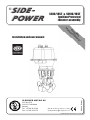 1
1
-
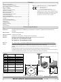 2
2
-
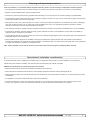 3
3
-
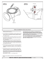 4
4
-
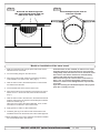 5
5
-
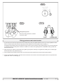 6
6
-
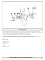 7
7
-
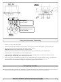 8
8
-
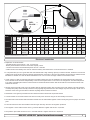 9
9
-
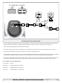 10
10
-
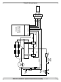 11
11
-
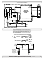 12
12
-
 13
13
-
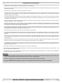 14
14
-
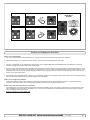 15
15
-
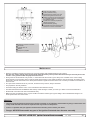 16
16
-
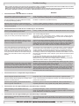 17
17
-
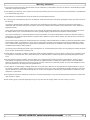 18
18
-
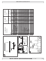 19
19
-
 20
20


Side-Power SE80/185T IP Installation and User Manual
- Category
- Toys & accessories
- Type
- Installation and User Manual
- This manual is also suitable for
Ask a question and I''ll find the answer in the document
Finding information in a document is now easier with AI
Related papers
-
Side-Power SEP 120/215T IP Installation and User Manual
-
-
-
-
-
-
Other documents
-
 exturn RC-11XE Installation & User Manual
-
Vetus DBPPJA User manual
-
Sleipner 90150I Installation guide
-
-
Sleipner SX50/140-12V-50POD User manual
-
Sleipner SE60/185S2-24V Installation guide
-
Sleipner SEP60/185S2-24V Installation guide
-
Sharp AH-A12FEF User manual
-
Sleipner SEP40/125S2-IP Installation guide
-
Sleipner SEP50/140S-24V Installation guide
