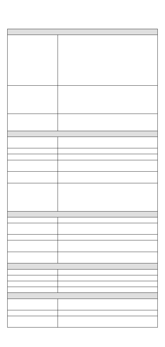
Moxa EDS-516A Series User manual

Category
Network switches
Type
User manual

Moxa EDS-516A Series, a high-performance industrial Ethernet switch, offers reliable and efficient network connectivity for harsh industrial environments. With its rugged design, wide temperature range, and advanced features, it's ideal for applications in factory automation, intelligent transportation systems, and power utilities. The EDS-516A features 14/16 Fast Ethernet ports and 2 Gigabit Ethernet ports, providing high bandwidth for data transmission.

Moxa EDS-516A Series, a high-performance industrial Ethernet switch, offers reliable and efficient network connectivity for harsh industrial environments. With its rugged design, wide temperature range, and advanced features, it's ideal for applications in factory automation, intelligent transportation systems, and power utilities. The EDS-516A features 14/16 Fast Ethernet ports and 2 Gigabit Ethernet ports, providing high bandwidth for data transmission.

2014 Moxa Inc. All rights reserved.
P/N: 1802005160014
EDS-516A Series
Hardware Installation Guide
Moxa EtherDevice™ Switch
Sixth Edition, April 2014
- 2 -
Package Checklist
Moxa EtherDevice™ Switch is shipped with the following items. If any of
these items are missing or damaged, please contact your customer
service representative for assistance.
1 Moxa EtherDevice Switch EDS-516A
Hardware Installation Guide
CD-ROM with User’s Manual and Windows Utility
Moxa Product Warranty Booklet
RJ45 to DB9 Console port cable
Protective caps for unused ports
Panel mounting kit (optionalmust order separately)
Optional Accessories
DR-452445W/2A DIN-Rail 24 VDC Power Supply with 85 to 264
VAC input
DR-75-2475W/3.2A DIN-Rail 24 VDC Power Supply with 85 to 264
VAC input
DR-120-24120W/5A DIN-Rail 24 VDC Power Supply with 88 to
132 VAC/176 to 264 VAC input by switch
EDS-SNMP OPC Server ProCD with EDS-SNMP OPC Server
Software and manual
WK-46Wall Mounting Kit
RK-4U4U-high 19" rack mounting kit
- 3 -
Panel Views of EDS-516A
1. Grounding screw
2. Console port
3. Heat dissipation orifices
4. 6-pin terminal block for DI 1,
DI 2, and PWR 2
5. 6-pin terminal block for PWR1
Relay 1, and Relay 2
6. 10/100BaseT(X), ports 1 to 16
7. PWR 1: LED for power input 1
8. PWR 2: LED for power input 2
9. Fault LED
10.
MSTR/HEAD LED
11.
CPLR/TAIL LED
12.
TP port’s 100 Mbps LED
13.
TP port’s 10 Mbps LED
14.
Model Name
15.
Screw hole for Wall Mounting
Kit
16.
DIN-Rail Kit
- 4 -
Panel Views of EDS-516A (SC/ST Type)
NOTE:
The appearance of
EDS
-516A-MM-ST
is identical to EDS
-516A-MM-SC.
1. Grounding screw
2. Console port
3. Heat dissipation orifices
4. 6-pin terminal block for DI 1,
DI 2, and PWR 2
5. 6-pin terminal block for PWR1
Relay 1, and Relay 2
6. 10/100BaseT(X), ports 1 to 14
7. PWR 1: LED for power input 1
8. PWR 2: LED for power input 2
9. Fault LED
10.
MSTR/HEAD LED
11.
CPLR/TAIL LED
12.
TP port’s 100 Mbps LED
13.
TP port’s 10 Mbps LED
14.
Model Name
15.
100BaseFX Port 15
16.
100BaseFX Port 16
17.
100BaseFX LEDs
18.
Screw hole for Wall Mounting
Kit
19.
DIN-Rail Kit
- 5 -
Mounting Dimensions
Unit = mm (inch)
- 6 -
DIN-Rail Mounting
The aluminum DIN-Rail attachment plate should already be fixed to the
back panel of EDS-516A when you take it out of the box. If you need to
reattach the DIN-Rail attachment plate to EDS-516A, make sure the stiff
metal spring is situated towards the top, as shown by the following
figures.
STEP 1
Insert the top of the
DIN
-Rail into the slot just below the
stiff metal spring.
STEP 2
The DIN-Rail attachment
unit will snap into place as shown
in
the following illustration.
To remove the EDS-516A from the DIN-Rail, simply reverse Steps 1 and
2 above.
Wall Mounting (Optional)
For some applications, you will find it convenient to mount Moxa
EDS-516A on the wall, as shown by the following illustrations:
STEP 1Remove the
aluminum DIN
-Rail
attachment plate from the
Moxa EDS
-516A rear
panel
, and then attach
the
wall mount plates
with M3
screws
, as shown by the
figure
on the right.
STEP 2
Mounting Moxa EDS-516A on the wall
requires 4 screws. Use the EDS
-516A
, with wall mount
plates attached, as a guide to mark the correct
locations of the 4 screws. The heads of the screws
should be less than 6.0 mm in diameter, and the shafts
should be less than 3.5 mm in diameter, as shown by
the figure on the right.
NOTE
Before tightening the screws into the wall, make sure the screw
head and shank size are suitable by inserting the screw through
one of the keyhole-shaped apertures of the Wall Mounting Plates.
Do not screw the screws in all the wayleave about 2 mm to allow room
for sliding the wall mount panel between the wall and the screws.
- 7 -
STEP 3Once the screws are
fixed
to the wall, insert the four
screw heads through the wide
parts of the keyhole
-shaped
apertures, and then slide
the
EDS
-516A downwards, as
in
dicated in the figure at
the right.
Tighten the four screws for
more
stability.
ATEX Information
1. Certification number DEMKO 09 ATEX 0812123X
2. Ambient range (-40°C Tamb 75°C)
3. Certification string (Ex nA nC IIC T4 Gc)
4. Standards covered ( EN60079-0:2012, EN 60079-15:2010)
5. The conditions of safe usage:
The Ethernet Communication Devices are to be mounted in an
IP54 enclosure and used in an area of not more than pollution
degree 2 as defined by IEC60664-1.
A 4mm2 conductor must be used when connection to the
external grounding screw is utilized.
Conductors suitable for use in an ambient temperature of 93°
C
must be used for the Power Supply Terminal.
Provisions shall be made, either in external to the apparatus, to
prevent the rated voltage being exceeded by the transients
disturbances of more than 40%.
Wiring Requirements
WARNING
Do not disconnect modules or wires unless power has been
switched off or the area is known to be non
-hazardous. The
devices may
only be connected to the supply voltage shown on
the type plate. The devices are designed for operation with a
Safety Extra
-
Low Voltage. Thus, they may only be connected to
the supply voltage connections and to the signal contact with the
Safety Extra
-Low Voltages (SELV) in compliance with IEC950/
EN60950/ VDE0805.
ATTENTION
This unit is a built
-in type. When the unit is installed in another
piece of equipment, the equipment enclosing the unit must
comply with fire
enclosure regulation IEC 60950/EN60950 (or
similar regulation).
- 8 -
ATTENTION
Safety First!
Be sure to disconnect the power cord before installing and/or
wiring your Moxa EtherDevice Switch.
Calculate the maximum possible current in each power wire and
common wire. Observe all electrical codes dictating the
maximum current allowable for each wire size.
If the current goes above the maximum ratings, the wiring could
overheat, causing serious damage to your equipment.
You should also pay attention to the following points:
Use separate paths to route wiring for power and devices. If power
wiring and device wiring paths must cross, make sure the wires are
perpendicular at the intersection point
NOTE: Do not run signal or communications wiring and power wiring
through the same wire conduit. To avoid interference, wires with
different signal characteristics should be routed separately
You can use the type of signal transmitted through a wire to
determine which wires should be kept separate. The rule of thumb is
that wiring that shares similar electrical characteristics can be
bundled together
Separate input wiring and output wiring
We advise that you label wiring to all devices in the system when
necessary.
Grounding the Moxa EDS-516A
Grounding and wire routing help limit the effects of noise due to
electromagnetic interference (EMI). Run the ground connection from the
ground screw to the grounding surface prior to connecting devices.
ATTENTION
This product is intended to be mounted to a well
-grounded
mounting surface such as a metal panel.
- 9 -
Wiring the Relay Contact
EDS-516A has two sets of relay outputsrelay 1 and relay 2. Each Relay
Contact consists of the two contacts of the terminal block on EDS-516A’s
top panel. You can refer to the next section for detailed instructions on
how to connect the wires to the terminal block connector, and how to
attach the terminal block connector to the terminal block receptor.
In this section, we will explain the meaning of the two contacts used to
connect the Relay Contact.
FAULT:
The two sets of relay contacts of
the 6
-pin terminal bl
ock connector
are used to detect user
-
configured
events. The two wires attached to
the
fault contacts form an open
circuit when a user
-configured
event is triggered. If a
user
-configured event does not
occur, the
fault circuit remains
closed.
Wiring the Redundant Power Inputs
EDS-516A has two sets of power inputspower input 1 and power input
2.The top two contacts and the bottom two contacts of the 6-pin terminal
block connector on EDS’ top panel are used for EDS’ two digital inputs.
The top and front views of one of the terminal block connectors are shown
here.
STEP 1: Insert the
negative/positive DC wires into
the V
-
/V+ terminals, respectively.
STEP 2:
To keep the DC wires
from pulling loose, use a small
flat
-blade screwdriver to tighten
the
wire-
clamp screws on the front
of the terminal block connector.
STEP 3:
Insert the plastic terminal
block connector prongs into the
terminal block receptor, which is
located on
the EDS-516A’s top
panel.
- 10 -
Wiring the Digital Inputs
EDS-516A has two sets of digital inputs, DI 1 and DI 2. Each DI consists
of two contacts of the 6-pin terminal block connector on EDS’s top panel,
which are used for EDS’s two DC inputs. The top and front views of one of
the terminal block connectors are shown here.
STEP 1: Insert the negative
(ground)/positive DI wires into the
/I1 terminals, respectively.
STEP 2: To keep the DI wires from
pulling loose, use a small
flat
-blade screwdriver to tighten
the wire
-
clamp screws on the front
of the terminal block connector.
STEP 3:
Insert the plastic terminal
block connector prongs into the
terminal block receptor, which is
located on
the EDS-516A’s top
panel.
Communication Connections
All models of EDS-516A have one RJ45 console port (RS-232 interface),
between 14 and 16 10/100BaseTX Ethernet ports. Some models also
have 2 100BaseFX (SC/ST-type connector) fiber ports.
In this section, we present two types of diagramsPinout Diagrams and
Cable Wiring Diagramsto convey information about the ports and the
cables used to connect Moxa EDS-516A to other devices:
PinoutsThe meaning of the “Pinouts” diagrams is straightforward. The
diagrams simply display the type of signal passing through each of the
port’s pins.
Cable WiringDiagrams labeled “Cable Wiring” present standard cable
wiring schemes for cables used to connect Moxa EtherDevice Switch’s
ports to other devices. These diagrams display three pieces of
information:
1. When building your own cable, refer to the “pin-to-pin Cable
Wiring information displayed between the two vertical dashed lines
to see which pin of the connector on the left should be connected to
which pin of the connector on the right.
2. The information to the left of the left vertical dashed lines gives the
pinouts of the relevant Moxa EtherDevice Switch port.
3. The information to the right of the right vertical dashed line gives the
pinouts of the opposing device’s port.
- 11 -
NOTE
1. The pin numbers for male DB9 and DB25 connectors, and
hole numbers for female DB9 and DB25 connectors are
labeled on the connector. However, the numbers are
typically quite small, so you may need to use a magnifying
glass to see the numbers clearly.
2. The pin numbers for both 8-pin and 10-
pin RJ45 connectors
(and ports) are typically not labeled on the connector (or
port). Refer to the following Pinout and Cable Wiring
diagrams to see how RJ45 pins are numbered.
RS-232 Connection
Moxa EDS-516A has one RS-232 (10-pin RJ45) console port, located on
the top panel. Use either an RJ45-to-DB9 or RJ45-to-DB25 cable (see the
cable following wiring diagrams) to connect Moxa EDS-516A’s console
port to your PC’s COM port. You may then use a console terminal program,
such as Moxa PComm Terminal Emulator, to access Moxa EDS-516A’s
console configuration utility.
RJ45 (10-pin) Console Port Pinouts
Pin
Description
1
---
2
DSR
3
RTS
4
---
5
TxD
6
RxD
7
GND
8
CTS
9
DTR
10
---
RJ45 (10-pin) to DB9 (F) Cable Wiring
- 12 -
RJ45 (10-pin) to DB25 (F) Cable Wiring
10/100BaseT(X) Ethernet Port Connection
The 10/100BaseT(X) ports located on Moxa EtherDevice Switch’s front
panel are used to connect to Ethernet-enabled devices. Most users will
choose to configure these ports for Auto MDI/MDI-X mode, in which case
the port’s pinouts are adjusted automatically depending on the type of
Ethernet cable used (straight-through or cross-over), and the type of
device (NIC-type or HUB/Switch-type) connected to the port.
In what follows, we give pinouts for both MDI (NIC-type) ports and MDI-X
(HUB/Switch-type) ports. We also give cable wiring diagrams for
straight-through and cross-over Ethernet cables.
10/100Base T(x) RJ45 Pinouts
MDI Port Pinouts
MDI-X Port Pinouts
8-pin RJ45
Pin
Signal
1
Tx+
2
Tx-
3
Rx+
6
Rx-
Pin
Signal
1
Rx+
2
Rx-
3
Tx+
6
Tx-
RJ45 (8-pin) to RJ45 (8-pin) Straight-through Cable Wiring
- 13 -
RJ45 (8-pin) to RJ45 (8-pin) Cross-Over Cable Wiring
100BaseFx Ethernet Port Connection
The concept behind the SC/ST port and cable is quite straightforward.
Suppose you are connecting devices I and II. As opposed to electrical
signals, optical signals do not require a circuit in order to transmit data.
Consequently, one of the optical lines is used to transmit data from device
I to device II, and the other optical line is used transmit data from device
II to device I, for full-duplex transmission.
All you need to remember is to connect the Tx (transmit) port of device I
to the Rx (receive) port of device II, and the Rx (receive) port of device I
to the Tx (transmit) port of device II. If you are making your own cable,
we suggest labeling the two sides of the same line with the same letter
(A-to-A and B-to-B, as shown by the following illustration, or A1-to-A2
and B1-to-B2).
SC-Port Pinouts
SC-Port to SC-Port Cable Wiring
ST-Port Pinouts
ST-Port to ST-Port Cable Wiring
ATTENTION
This is a Class 1 Laser/LED product. To prevent damage to your
eyes, do not stare directly into the laser beam.
- 14 -
LED Indicators
The front panel of Moxa EDS-516A contains several LED indicators. The
function of each LED is described in the following table:
LED
Color
State
Description
PWR1 AMBER
On
Power is being supplied to power
input P1.
Off
Power is
not
being supplied to power
input P1.
PWR2 AMBER
On
Power is being supplied to power
input P2.
Off
Power is not being supplied to power
input P2.
FAULT RED
On
When the corresponding PORT alarm
is enabled, and a user-configured
event is triggered.
Off
When the corresponding PORT alarm
is enabled and a user-configured
event is not triggered, or when the
corresponding PORT alarm is
disabled.
MSTR/HEAD
GREEN
On
When the EDS-516A is set as the
Master of the Turbo Ring, or as the
Head of the Turbo Chain.
Blinking
The EDS-516A has become the Ring
Master of the Turbo Ring, or the Head
of the Turbo Chain, after the Turbo
Ring or the Turbo Chain is down.
Off
When the EDS-
516A is not the Master
of this Turbo Ring or is set as the
Member of the Turbo Chain.
CPLR/TAIL GREEN
On
When the EDS-516A coupling function
is enabled to form a back-
up path, or
when it's set as the Tail of the Turbo
Chain.
Blinking
When the Turbo Chain is down.
Off
When the EDS-516A disables the
coupling function.
10M
(TP)
GREEN
On
TP port’s 10 Mbps link is active.
Blinking
Data is being transmitted at 10 Mbps.
Off
TP port’s 10 Mbps link is inactive.
100M
(TP)
GREEN
On
TP port’s 100 Mbps link is active.
Blinking
Data is being transmitted at 100
Mbps.
Off
TP port’s 100 Mbps link is inactive.
- 15 -
Specifications
Technology
Standards IEEE 802.3 for 10BaseT,
IEEE 802.3u for 100BaseT(X) and 100Base FX,
IEEE 802.3x for Flow Control,
IEEE 802.1D for Spanning Tree Protocol,
IEEE 802.1w for Rapid STP,
IEEE 802.1Q for VLAN Tagging,
IEEE 802.1p for Class of Service,
IEEE 802.1X for Authentication,
IEEE 802.3ad for Port Trunk with LACP
Protocols
IGMPv1/v2, GMRP, GVRP, SNMPv1/v2c/v3,
DHCP Server/Client, DHCP Option 66/67/82,
BootP, TFTP, SNTP, SMTP, RARP, RMON, HTTP,
HTTPS, Telnet, SSH, Syslog, IPv6, LLDP, IEEE
1588 PTP, Modbus/TCP, SNMP Inform
MIB
MIB-II, Ethernet-like MIB, P-BRIDGE MIB,
Q-BRIDGE MIB, Bridge MIB, RSTP MIB, RMON
MIB Group 1,2,3,9
Interface
RJ45 Ports
10/100BaseT(X) auto negotiation speed, F/H
duplex mode, and auto MDI/MDI-X connection
Fiber Ports
optional 100BaseFX (SC/ST connector)
Console Port
RS-232 (10-pin RJ45)
LED Indicators
PWR1, PWR2, FAULT, 10/100M (TP port),
MSTR/HEAD and CPLR/TAIL
Alarm Contact
Two relay outputs with current carrying capacity
of 1A @ 24 VDC
Digital Input Two inputs with the same ground, but
electrically isolated from the electronics
• For state “1”: +13 to +30V
• For state “0”: -30 to +3V
• Max. input current: 8 mA
Power
Input Voltage
24 VDC (12 to 45 VDC), redundant inputs
Input Current (@24V)
0.44A: (EDS-516A)
0.51A: (EDS-516A-MM-SC/ST)
Connection
Two removable 6-pin terminal blocks
Overload Current
Protection
Present
Reverse Polarity
Protection
Present
Mechanical
Casing
IP30 protection, metal case
Dimensions
95 × 135 × 140 mm (W × H × D)
Weight
1.586 kg
Installation
DIN-Rail, Wall Mounting (optional kit)
Environment
Operating Temperature
0 to 60°C (32 to 140°F)
-40 to 75°C (-40 to 167°F) for -T models
Storage Temperature
-40 to 85°C (-40 to 185°F)
Ambient Relative
Humidity
5% to 95% (non-condensing)
- 16 -
Regulatory Approvals
Safety
UL 508, UL 60950-1
CSA C22.2 No. 60950-1, EN 60950-1
Hazardous Location
UL/cUL Class I, Division 2, Groups A, B, C, and
D, ATEX Zone 2, Ex nA nC IIC T4 Gc
EMI
FCC Part 15, CISPR (EN 55022) class A
EMS
EN 61000-4-2 (ESD), Level 2
EN 61000-4-3 (RS), Level 3
EN 61000-4-4 (EFT), Level 2
EN 61000-4-5 (Surge), Level 3
EN 61000-4-6 (CS), Level 3
EN 61000-4-8
EN 61000-4-11
EN 61000-4-12
Shock
IEC 60068-2-27
Freefall
IEC 60068-2-32
Vibration
IEC 60068-2-6
WARRANTY
5 years
Technical Support Contact Information
www.moxa.com/support
Moxa Americas:
Toll
-free: 1-888-669-2872
Tel:
1-714-528-6777
Fax:
1-714-528-6778
Moxa China (Shanghai office):
Toll
-free: 800-820-5036
Tel:
+86-21-5258-9955
Fax:
+86-21-5258-5505
Moxa Europe
:
Tel:
+49-89-3 70 03 99-0
Fax:
+49-89-3 70 03 99-99
Moxa Asia
-Pacific:
Tel:
+886-2-8919-1230
Fax:
+886-2-8919-1231
  • Page 1 1
  • Page 2 2
  • Page 3 3
  • Page 4 4
  • Page 5 5
  • Page 6 6
  • Page 7 7
  • Page 8 8
  • Page 9 9
  • Page 10 10
  • Page 11 11
  • Page 12 12
  • Page 13 13
  • Page 14 14
  • Page 15 15
  • Page 16 16

Moxa EDS-516A Series User manual

Category
Network switches
Type
User manual

Moxa EDS-516A Series, a high-performance industrial Ethernet switch, offers reliable and efficient network connectivity for harsh industrial environments. With its rugged design, wide temperature range, and advanced features, it's ideal for applications in factory automation, intelligent transportation systems, and power utilities. The EDS-516A features 14/16 Fast Ethernet ports and 2 Gigabit Ethernet ports, providing high bandwidth for data transmission.

Ask a question and I''ll find the answer in the document

Finding information in a document is now easier with AI