Page is loading ...

Texmate, Inc. Tel. (760) 598-9899 • www.texmate.comFL-B101Q_UL (FL6) Page 1
Smart mono-color digital bargraph
with four fully programmable set points for
monitoring, measurement, and control applications.
• Two9AmpFormC,andtwo4AmpFormArelaysavailable
•
Auto-sensing AC/DC power supply. For voltages between
85-265 V AC / 95-300 V DC (PS1)or15-48VAC/10-72VDC(PS2).
• Optionalisolated16bitanalogoutput.Userorfactoryscalable
to4to20mA,0to20mAor0to10Vacrossanydesiredspan
from±onebartothefullscalerange
•
Provisiontoconnectanexternalprogramminglockoutswitch.
• OptionalNEMA-4frontcover.
• 24 V DC excitation is available to power external 4/20 mA
transmitters and 5 or 10 V DC excitation is available for
resistancebridgetypesensors.
• ULListed
• Thetwo101segmentbargraphcanbeindependentlyscaled.
•
Bargraphcenterzerofunction.
•
Fourprogrammablesetpoints.
• Relaysactivationcanbeselectedtooccurabove(HI)orbelow(LO)
eachsetpoint.
• Decimalpointsetting.
Input Specs:..............
Dependsonrangeandfunctionselected
A/D Converter:..........14bitsingleslope
Accuracy:..................±(0.05%ofreading+1segment)
Temp. Coeff.:.............100ppm/°C(Typical)
Warm up time:...........2minutes
Conversion Rate:......10conversionspersecond(Typical)
Bargraph Display:.....
101 segment 4” vertical (std),
horizontal (optn), red (std), green (optn),
oneredonegreen(optn)
Polarity:.....................Selectablecenterzero
Positive Overrange:. . Bargraphdisplayflashes
Negative Overrange:
Firstsegmentofbargraphdisplayflashes
Relay Output:............Two 4 Amp Form A relays and Two
9AmpFormCrelays
Analog Output:.........Isolated16bituserscalablemAorV
OIC(mAout)...........
4-20mA@0to500Ωmaxloopresistance
OIV(voltsout).......... 0-10VDC@500Ωorhigherresistance
Power Supply:...........AC/DCAutosensingwiderangesupply
PS1 (std)................
85-265 VAC, 50-400 Hz / 95-300 VDC @ 4.2W
PS2.........................
15-48VAC,50-400Hz/10-72VDC@4.2W
Operating Temp.:......0to50°C
Storage Temp:...........–20°Cto70°C
Relative Humidity:....95%(noncondensing)
Case Dimensions:....
3/32DIN,Bezel:36x144mm(1.42”x5.69”)
Depth behind bezel: (4.64") 117.5 mm
Plus 10 mm (0.39”) for Right-angled con-
nector,orplus18.3mm(0.72”)forStraight-
thruconnector,orplus26.5mm(1.05”)for
Push-Onconnector.
Weight:.......................9.5oz.,12ozwhenpacked
General Features
Input Module Compatibility
Specifications
Index
Software Features
Center Bar
for Dual Scale
Applications
(Tri-Color or
Mono-Color)
Left or Right Bar to match 6” Edgewise
Mechanical Meters with Left or Right
Pointers (Mono-Color only)
LEOPARD FAMILY
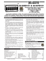
FL-B101Q
Leopard Bargraph Meter
101 Segment LEDs
in a 9/64 DIN CASE
LEOPARD
✔ LEOPARD FAMILY: More than 50 different
Plug-in I-Series Input Signal Conditioners are
approvedforLeopardFamilymeters. Some exam-
plesareshownonpages12-14.Checkwithyour
localdistributorsforanuptodatelisting.
AnalogOutputScalingandCalibration ...........9
CaseDimensions...........................15
CenterZeroModeScalingforBipolarInputs.... 6-7
ComponentLayout.........................11
ConnectorPinouts ..........................10
Connectors................................ 11
ControlsandIndicators.......................2
CustomFacePlatesandScale................17
GlossaryofProgrammingSymbolsandModesof
Operation ..................................2
FunctionalDiagram.........................10
GeneralFeatures ............................1
InputModuleCompatibility....................1
InputModuleComponentGlossary...............
16
Installation................................15
I-SeriesInputSignalConditioningModules... 12-14
OnePointQuicksetRescalingandCalibration
Procedure.................................6
OrderingInformation........................18
OpeningtheCasetoAccessModeSelectHeaders...4
OverviewofDisplayModes,ScalingCapabilitiesand
OperationModes ............................3
PinDescriptions ............................10
SetpointAdjust ............................ 7-8
SettingtheColors...........................8
SoftwareFeatures...........................1
Specifications ...............................1
StandardDisplayModeCalibrationProcedure... 5-6
TwoPointQuicksetScalingandCalibration .......5
E469078

Texmate, Inc. Tel. (760) 598-9899 • www.texmate.comPage2 FL-B101Q_UL (FL6)
Standard or Center Zero Display Mode Select Header
•
Jumperclipsenablesstandard
displayonCH1andCH2.
•JumpercliptoenableCenter
Zerodisplay.
Operating Mode Select Header
Thisheaderselectsoneofthetwobasicoperating
modespresentlyavailableforthismeter.
Mode0Bargraphwithfoursetpointsdisplayedon
bargraphdisplay.
Mode3EnablestheHysteresismodefortank
fillingortankemptyingapplications.
Relay Activation Mode Select Header
Whennojumperclipsareinstalledtherelayswill
activatewhenthedisplayexceedsthesetpoint.
Anyrelaythathasajumperclipinstalledwill
activatewhenthedisplayislessthanthesetpoint.
CH1 CH2
CH1 CH2
MODE
13
2
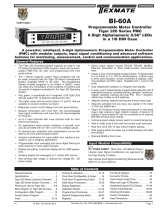
Controls and IndicatorsControls and Indicators
101SegmentBar
Setpointindicated
byanOFFSegment
UPButtonIndicator
DOWNButton
Indicator
Setpointindicated
byanONSegment
Quickset Programming
ThisbargraphfeaturesTexmate'suniqueQUICKSETPROGRAMMING.
Whenafrontpanelbuttonispressedtheassociatedfunctionisdirectly
changed.Thedirectionofchangewillbeeitherupordown,asindicat-
edbytheUPandDOWNindicatorLEDs.AftertheindicatorLEDlights
upthereisa0.5seconddelaybeforeanychangeoccurs.Whenabut-
tonisreleasedandpressedagainthedirectionofchangeisreversed.
Astherearenomenuorsub-menustonavigate,theprogrammingand
setupisquickand
SpanButtons
Span
ZeroButtons
Zero
SetPointButton
SP1
SP2
SP3
SP4
Front Panel Buttons
Zero Button
TheZeroButtonsetstheChannel1lowinputsignalscaling.
Span Button
TheSpanButtonsetstheChannel1highinputsignalscaling.
SP1, SP2, SP3 and SP4 Buttons
Thesebuttonssetupthecorrespondingsetpoints.
Setpoint Indication
Thepositionofsetpointsonthebargraphdisplayareindicatedby
anONsegmentifthebargraphdisplayisbelowthesetpoint,and
byanOFFsegmentifthebargraphdisplayisabovethesetpoint.
(Seethedrawingabove)
Toexplainsoftwareprogrammingprocedures,logicdiagrams
areusedtovisuallyassistinfollowingprogrammingsteps.The
followingsymbolsareusedtorepresentthefunctionsanddis-
playsofthemeter:
When two fingers are shown side by
side,thetwocorrespondingbuttonsmust
bepressedatthesametimetoinitiatean
indicatedfunction.
Controls and IndicatorsGlossary of Programming Symbols and Modes of Operation
Input Hi
Input Low
Thisarrowrepresents
thedirectionandlevel
ofaninputsignal
Smallarrowshows
directionthebar-
graphdisplayhas
movedorwillmove.
Shadingindicates
bargraphisONin
thisarea.
Setpointindicatedby
anOFFsegment.
Setpointindicatedby
anONsegment.
Zero Span
Center Bar Display Option
This display option can be selected
when a dual scale is required. A
customfaceplateisrequiredfordual
scales. Tri-Color option is available
onlyfortheCenterBardisplay.
MODE
13
2
RELAYS
1
34
2

Texmate, Inc. Tel. (760) 598-9899 • www.texmate.comFL-B101Q_UL (FL6) Page 3
Overview of Display Modes, Scaling Capabilities and Operating Modes
Input Hi
Input Low
std
Input Hi
Input Low
std Inv
FLB202Q MODE O1
+ Input
- Input
+ Input
- Input
+ Input
- Input
000
biploar center zero
Input Hi Input HiInput Hi
Input Low Input Low
Input Low
center zero
1/21/21/2
Standard Scaling
Standarddisplaymodeselectedand
scaledsobarincreasesasinputsignal
increasesfromLowtoHi.
Halfway Zero Point
Centerpointdisplaymodeselectedand
scaled,sothebarincreasesupwardsor
downwardsfromthecenterpoint,forsig-
nalsthataregreaterorlessthanhalfthe
calibratedfullscalerangerespectively.
Whentheinputisequaltohalfthefull
scalerange,onlythecentersegmentwill
beon.
Inverse Scaling
Standarddisplaymodeselectedand
scaledsothebarincreasesastheinput
signaldecreasesfromHitoLow.
Bipolar Center Zero
Centerpointdisplaymodeselectedand
scaled,sothebarincreasesupwardfrom
zero,forincreasingpositiveinputsand
downwardfromzeroforincreasingnegative
inputs.Whentheinputiszero,onlythecen-
tersegmentwillbeon.
CH1 CH2
Standard Display Mode
CH1 CH2
Center Zero Display Mode
min_max
SP1
SP2
SP3
SP4
dual bar rvsd
SP1
SP2
SP3
SP4
Display with 4 Set Points
WithStandarddisplayorCenterpoint
modeselected,thesetpointsare
indicatedbyanONsegmentoutside
thebardisplayareaandbyanOFF
segmentinsidethebardisplayarea.
Horizontal or Reverse Mounting
Meterscanbemountedhorizontallyin
thepanelandforthoseapplicationsthat
requireanoppositegrowthofthebar,
themetercanbeverticallyorhorizontally
mountedupsidedown
Mode 0 Channel Inputs Horizontal and Reverse Mounting
withCustomFacePlateInstalled
Mode 3 Hysteresis Band between SP1 & SP2
ThismodeenablestheHysteresisfunction.InorderforHysteresistofunction,SP2mustbesettoavaluegreaterthanSP1,andSP2shouldbe
selectedasHigh(h)Setpoint(Seepage7).Whentheseconditionsaremet,andMode3isselected,thenaHysteresisbandiscreatedforthe
SP1relay,withtheupperlimitofSP2andthelowerlimitofSP1.SP2relaycontinuestooperatenormally.
•ForatankfillingapplicationSP1issettoaLow(L)Setpoint.SP1relaycancontrolapumpthatfillsthetank
WithMode3selected,SP1relayactivatesforinputslessthantheSP1level.Onceactivated,SP1relaywill
stayONuntilthetankisfilledtotheSP2level.
•ForatankemptyingapplicationSP1issettoaHigh(h)Setpoint.SP1cancontrolapumpthatemptiesthe
tank.WithMode3selected,SP1relayactivatesforinputsgreaterthantheSP2level.Onceactivated,SP1
relaywillstayONuntilthetankisemptiedtotheSP1level.
MODE
13
2
Tank Filling
SP1 Tank starts
filling when
level is at or
below SP1
SP2
SP1
Tank stops
filling when
level is at SP2
SP2
Tank Emptying
SP1 Tank stops
emptying when
level is at SP1
SP2
SP1
Tank starts
emptying when
level is at or
above SP2
SP2
MODE
13
2

Texmate, Inc. Tel. (760) 598-9899 • www.texmate.comPage4 FL-B101Q_UL (FL6)
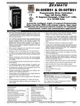
ThemodeselectheadersarelocatedontheDisplayDriverBoardassembly.Tochangeanyofthemodes,itisbesttoremovethe
DisplayDriverBoardassemblyfromthecase.BeforeremovingtheDisplayDriverBoardassemblyfromthefrontofthecaseitis
necessarytoremovetherearcoverandslidethemainboardbackaninch,orremoveit,todisengagethepinandsocketconnector
betweenthemainboardandthedisplayassembly.
Step 2
Removetherearcoverplate
bypressingdownlightlywitha
smallflatbladedscrewdriver
toreleasetwoplasticcatches,
oneithersideofthecaseand
leveringbackwards.
Step 4
Startingwiththetopfirst,inserta
smallflatbladedscrewdriverand
carefullylevertheplasticcatchup
andtilttheDisplayBoardassembly
forward.Thenrepeatthisaction
withthebottomcatches.
Step 5
RemovetheentireDisplayBoard
assemblybyslidingitoutofcase.
Opening the Case to Access Mode Select Headers
INPUT SIGNAL
CONDITIONER
MAIN BOARD
DISPLAY BOARD
DRIVER BOARD
Meter Exploded view
Optional 16 Bit Isolated Analog Output Module
4 to 20 mA
(
0 to 20 mA
)
S
election Positio
n
0
to 1
0
V D
C
S
election Positio
n
Analog Output
S
election Heade
r
CH1 CH2
Standard or
Center Zero
Display Mode
Select Header
13
2
Operating Mode
Select Header
134
2
Relay Activation Mode
Select Header
b
a
c
d
Frontviewwithbezeland
scalefaceplateremoved.
Step 1
Removethefrontbezelby
lightlyleveringtheplastic
catchesupandforwardin
theabcdsequenceshown.
Thenremovethecoverand
scalefaceplate.
Step 3
SlidetheMainBoardback
approximately1”todisengage
thepinandsocketconnection
totheDisplayDriver
Board.

Texmate, Inc. Tel. (760) 598-9899 • www.texmate.comFL-B101Q_UL (FL6) Page5
MeterswithQUICKSET PROGRAMMINGfeatureaunique,easy-to-use,twopointscalingandcalibrationsystem.
Scalingorcalibrationisaccomplishedsimply,byapplyingazeroorlowinputsignalandadjustingthebartothedesired
reading,usingtheZERObutton.Ahigherinputsignalisthenapplied,andthebarisadjustedtothedesiredreadingfor
thatinputvalue,usingtheSPANbutton.
IMPORTANT DETAILS THAT MAKE QUICKSET PROGRAMMING EASY TO USE AND UNDERSTAND
1. Thezeroandspanbuttonsarefunctionallythesame,exceptasfollows:TheZERObuttoncaninitiateascalingwith
inputsignalsfromzeroto95%offullscale.TheSpanbuttoncaninitiateascalingwithinputsignalsfrom5%offullscale
to105%offullscale.
2. WhenaZeroorSpanbuttonispressed,theUporDownindicatorLEDwillimmediatelylightuptoshowthedirection,
inwhichtheBarwillmove,aftera0.5seconddelay.Ifthebuttonisreleasedandpressedagain,theoppositeUpor
Downindicatorwilllightup,and0.5secondslatertheBarwillbegintomoveinthatdirectionuntilthebuttonisreleased.
Whenthebarisbeingadjustedtozeroorfullscale,thebarwillautomaticallystopatthezeroorfullscaleposition,and
willnotovershootthesepositions,evenifthebuttoncontinuestobepressed.
3. Whilethebarisbeingadjusted,anewoffsetandscalefactoriscontinuouslybeingcalculated.Atthemomentthebutton
isreleased,andthescalingisaccepted,thecalculationdataismemorizedandimplemented.TheScalingcalculation
isbasedon thenewpositionoftheBar,theinputsignalbeingappliedatthatmoment,andthepreviouslymemorized
positionoftheBarandtheinputsignalthatwasbeingapplied,whentheotherbuttonwaslastreleased.
4. Positiveandnegativesignalsmaybeintegratedintoatwopointscaling.HoweverwheneitheraZEROorSPANbutton
ispressedtheinputsignalbeingapplied,mustbemorethan5%higherorlowerthanthepreviouslymemorizedvalue
oftheinputsignal,thatwasbeingappliedwhentheotherbuttonwaslastreleased.Ifnot,thebarwillflash,thescaling
willnotbeaccepted,andthepreviousscalingwillstillberetainedinmemory.
5. Becauseoftherequirement,that a newscalinginputsignalmustbe5% higherorlowerthanthepreviouslystored
value,itcansometimesbedifficulttoimplementadesiredscaling,particularlywhenusingacalibratorthatonlyhas
fixedoutputvalues.InthiscaseResettheScalingbypressingtheZEROandSPANbuttonssimultaneouslyfortwo
seconds. Both scaling memories will be erased and an internal default scale factor will be loaded. This provides a
displayofzerotofullscaleonthebarforaninputofapproximately0to100%oftherangeselectedontheinputsignal
conditioningmodule.AfterResettingtheScalinganewcalibration,usingeitherbutton,canbeimplementedwithnew
inputsignalvalues.ItisgoodpracticetoalwaysusetheZerobuttonforlowerinputsignalsandtheSpanbuttonfor
higherinputsignals,evenwhenthebardisplayscaleisinversed.
6. Thelargerthedifferencebetweentwopointsusedforcalibration,thebettertheaccuracy.Howeverifthedifferenceis
toohigh,andtheoutputfromtheinputsignalconditioningmoduleisgreaterthan+2.1VDC,orlessthan-1.05VDC,
thebarwillflashoverrange.Thecalibrationwillnotthenbeacceptedand,thepreviousscalingwillstillberetained
inmemory.Inthiscase,eitheralowerinputsignalmustbeused,orahigherrangeontheinputmoduleshouldbe
selectedtorecalibratethemeter.
Note:Mostinputsignalconditionershaveprovisionsforanalogcalibrationandscaling.Ifthemeter’sscalefactorisset
toreadzerowithazeroinput(shortedinput),andtoread10Barsfullscalewitha2.000Vinput,anypre-calibratedsignal
conditionerwithanoutputthatdoesnotexceed–1Vto+2V,willreadcorrectlyinthemeterwithoutanyfurthercalibration.
STEP A REVIEW THE INPUT MODULE STATUS
1) Seepages12-14forinformationoninputmodulesthatmaybeusedwith
thismeter.
2) Confirmthatthecorrectrangeandinputisselectedontheinputsignalcon-
ditioningmodule.
Note: Whenundertakinganinitialsetupandprimaryscalingandcalibrationofthemeter
itisbesttostartwitharesetofthescaling.
STEP B RESET THE SCALING
1)ApplypowertothemeterandpresstheZEROandSPANbuttonssimultaneouslyfor
2seconds.Thiserasesanypreviouslymemorizedscalings,andresetsthescalingto
thefactorydefault,ofapproximatelyzerotofullscale,foraninput,thatis0to100%of
therangeselectedontheinputsignalconditioner.
Standard or Center Zero Display Modemaybeselected,dependingontheOperatingModeselected.If
thestandarddisplaymodeisnotalreadyselectedopenthemetercaseasshowingonpage4andmovethe
jumperclipsonthedisplaymodeselectheadertotheOFFposition.
StandardDisplaywith
JumperClipsinOFF
position
Two Point Quickset Scaling and Calibration
Standard Display Mode Calibration Procedure
CH1 CH2
100
0
SP1 SP2 SP3 SP4
Zero Span
Reset the scaling
to the default value
on by pressing
the Zero and
Span buttons
simultaneously
for 2 secs.

Texmate, Inc. Tel. (760) 598-9899 • www.texmate.comPage6 FL-B101Q_UL (FL6)
Note:Tocalibratethebargraphyoumustbeabletoinputtwoinputsignals.Usuallytheminimum
input(LOInput)andthemaximuminput(HIInput)signalsareusedforoptimumaccuracy.However
ascalingcanbeaccomplishedwithanytwosignalsthatarehigherorlowerthaneachotherbymore
than5%offullscaleandarenotgreaterthan+2.1VDCorlessthan-1.05VDC.
STEP C SET THE LOW INPUT SIGNAL READING ON THE BAR
1) ApplytheLOinputsignal(4mainthisexample)totheinputpins.
2) UsingtheZERObuttonadjustthebardowntotherequiredposition.
STEP D SET THE HIGH INPUT SIGNAL READING ON THE BAR
1) Applythehighinputsignal(20mAinthisexample)totheinputpins.
UsingtheSPANbuttonadjustthebartotherequiredposition.
Thispositioncouldbehigherorlowerthanthepositionadjustedin
Step2.Thescalingforaninputof4to20mAisnowcomplete.
Apply 4 mA
to the
Input Pins
and adjust
bar display
to the required
position
100
0
SP1 SP2 SP3 SP4
Zero Span
Apply 20 mA
to the
Input Pins
and adjust
bar display
to the required
position
100
0
SP1SP2 SP3SP4
Zero Span
STEP A SELECT THE CENTER ZERO DISPLAY MODE FOR CH1
1) Followingtheinstructionsonpage4,removethemeterfromthecase.
2) SelecttheCenterZeroModeforCH1byrepositioningthejumperclipontheCenter
ZeroDisplayModeSelectHeader.
STEP B REVIEW THE INPUT MODULE STATUS
1) Seepages15–21forinformationoninputmodulesthatmaybeusewiththis
meter.
2) OnlytheIDP4UniversalInputmodulecanbeusedfordualinputsandinformation
onthismodulecanbefoundonpage15.
3) Confirmthatthecorrectrangeandinputisselectedontheinputsignalconditioning
module.
Note: Whenundertakinganinitialsetupandprimaryscalingandcalibrationofthemeteritisbest
tostartwitharesetofthescaling.
STEP C RESET THE SCALING ON CHANNEL ONE
1) ApplypowertothemeterandpresstheCH1ZEROandCH1SPANbuttons
simultaneouslyfor2seconds.Thiserasesanypreviouslymemorizedscalings,
andresetsthescalingtothefactorydefault,ofapproximatelyzerotofullscale,
foraninput,thatis0to100%oftherangeselectedontheinputsignal
conditioner.
Theprocedureforscalingthebargraphforbipolarsignalsisverysimple.IfsayCH1hastobescaledfor-1Vto+1V,thestepsare
asfollows:
CH1 CH2
CH1,Center
ZeroMode
Selected
100
0
SP1 SP2 SP3 SP4
Zero Span
Reset the scaling
to the default value
on by pressing
the Zero and
Span buttons
simultaneously
for 2 secs.
Standard Display Mode Calibration Procedure Continued
One Point Quickset Rescaling and Calibration Procedure
Center Zero Mode Scaling For Bipolar Inputs
ONE POINT RECALIBRATION
Asexplainedearlier,theFL-B101Qbargraphiscalibratedusingtwopointcalibration.Onceabargraphiscalibrated,the
lowendoftherangemaybethenrecalibratedwithoutaffectingthecalibrationofthehighend,andviceversa.
Forexample,takeanFL-B101Qthathasbeencalibratedtoreadzerotofullscaleforaninputof4to
20mA.Ifnowthescalinghastobechangedtoreadzerotofullscaleforaninputof0to20mA,only
thelow(4mA)endneedstoberecalibrated.Thehigh(20mA)endofthescalingisleftuntouched,
andsodoesnotchange.Thefollowingonepointrecalibrationprocedureisusedforthispurpose.
STEP A RECALIBRATE THE LOW INPUT SIGNAL READING ON THE BAR
1) ApplytheLOinputsignal(0mainthisexample)totheinputpins.
Thefirstsegmentwillflash,indicatinganunderrangecondition.
2) UsingtheZERObuttonadjustthebaruptotherequiredposition.
3) TheFL-B101Qhasnowbeenrecalibratedtoreadzerotofullscale
fora0to20mAinput.
Apply 0 mA
to the Input Pins
and adjust
bar display
to the required
position
100
0
SP1SP2 SP3SP4
Zero Span

Texmate, Inc. Tel. (760) 598-9899 • www.texmate.comFL-B101Q_UL (FL6) Page7
Apply -1V
to the
Input Pins
and adjust
bar display
to the required
position
100
0
SP1SP2 SP3 SP4
Zero Span
Apply +1V
to the
Input Pins
and adjust
bar display
to the required
position
100
0
SP1 SP2 SP3SP4
Zero Span
STEP D SET THE LOW INPUT SIGNAL READING ON THE BAR
1) ApplytheLOinputsignal(-1Vinthisexample)totheCH1inputpins.
2) UsingtheCH1ZERObuttonadjustthebardowntotherequiredposition.Inthis
case,allthebarsegmentsfrommidpointdowntothebottomwillbeON.
STEP E SET THE HIGH INPUT SIGNAL READING ON THE BAR
1) Applythehighinputsignal(+1Vinthisexample)totheCH1inputpins.
2) UsingtheCH1SPANbuttonadjustthebartotherequiredposition.Thisposition
couldbehigherorlowerthanthepositionadjustedinStep2.Inthiscase,allthe
barsegmentsfrommidpointuptothetopwillbeON.
3) ThescalingofCH1foraninputof-1Vto+1Visnowcomplete.
Center Zero Mode Scaling For Bipolar Inputs continued
Setpoint Adjust
Thebargraphhastheoptiontohaveupto4setpoints(two9AFormCrelaysandtwo4AFormArelays)installed.Eachrelaymay
besettoactivateeitheraboveorbelowitssetpointbyinsertingjumperclipsontheRelayActivationheaderwhichislocatedonthe
DisplayDriverBoard.SeethelayoutdiagramonPage4fortheexactlocation.Thestepstosetupthesetpointsareasfollows:
1) SELECT THE RELAY ACTIVATION MODE FOR EACH INSTALLED RELAY
Makesurethattherequiredrelayshavebeeninstalledinthemeter.RefertothecomponentlayoutonPage11forrelayposi-
tions.IfajumperclipisinstalledinaspecificrelaypositionontheRelayActivationModeHeader,thatrelaywillactivatewhen
thedisplaybarislowerthattheprogrammedsetpoint.IfnojumperclipisinstalledinaspecificrelaypositionontheRelay
ActivationModeHeader,thatrelaywillactivatewhenthedisplaybarisequaltoorhigherthattheprogrammedsetpoint.The
Diagramsbelowshowsomeofthevariouspossibilitiesforrelayactivation.
Default
SP1,SP2,SP3,andSP4allactivatewheninputisequaltoorhigherthansetpoint.
SP2andSP4activatewheninputislowerthansetpoint.SP1andSP3activatewheninput
isequaltoorhigherthansetpoint.
SP2activatewheninputislowerthansetpoint.SP1,SP3andSP4activatewheninputis
equaltoorhigherthansetpoint.
134
2
SP
134
2
SP
134
2
SP
SP1andSP3activatewheninputislowerthansetpoint.SP2andSP4activatewheninput
isequaltoorhigherthansetpoint.
SP1,SP2,SP3,andSP4allactivatewheninputislowerthansetpoint.
134
2
SP
SP1andSP2activatewheninputislowerthansetpoint.SP3andSP4activatewheninput
isequaltoorhigherthansetpoint.
134
2
SP
134
2
SP

Texmate, Inc. Tel. (760) 598-9899 • www.texmate.comPage8 FL-B101Q_UL (FL6)
100
0
25
50
75
SP1 SP2 SP3 SP4
Zero Span
SP2
SP1
SP3
SP4
2) ADJUST THE SETPOINT FOR EACH RELAY
ThesetpointforeachrelayissetbythefrontpanelbuttonsmarkedSP1,SP2,SP3and
SP4.Whenafrontpanelbuttonispressedandhelddown,theassociatedsetpointisdirectly
changed.Thedirectionofchangewillbeeitherupordown,asindicatedbytheUPandDOWN
indicatorLEDs.AftertheindicatorLEDlightsupthereisa0.5seconddelaybeforeanychange
occurs.Toreversethedirectionofchange,releasethebuttonandthenpressdownagain.As
therearenomenusorsub-menustonavigate,theprogrammingandsetupisquickandeasy.
SetpointsareindicatedonthebardisplaybyanONsegmentifthebarisbelowthesetpoint
andwithanOFFsegmentifthebardisplayisabovethesetpoint.
Setpoint Adjust continued
Setting the Colors (For CHT or CVT Center Bar display options only)
100 212
032
SP1 SP2 SP3 SP4
Zero Span Lo
output
Hi
Apply power
while holding down
SP1, SP2, SP3, SP4 SP2
SP1
SP3
SP4
100 212
032
SP1 SP2 SP3 SP4
Zero Span Lo
output
Hi
Select required
color (i.e. orange)
SP1
100 212
032
SP1 SP2 SP3 SP4
Zero Span Lo
output
Hi
Select required
color (i.e. Green)
SP2
100 212
032
SP1 SP2 SP3 SP4
Zero Span Lo
output
Hi
Select required
color (i.e. Orange)
SP3
100 212
032
SP1 SP2 SP3 SP4
Zero Span Lo
output
Hi
Select required
color (i.e. Red)
SP4
Tocomplywiththelatestsafetyrequirements,thetri-colorbargraphisdesignedlikeatrafficlight,to
displayeitherred,orangeorgreen,butonlyonecoloratatime.Whenthebarreachesaselected
colorchangepoint,theentirebarwillchangetothecolordesignatedforthatzone.Thiseliminates
anyambiguityastothesignalstatus,especiallyjustaftertransitioningtoanewzone.
However,iftwoormoresetpointswithdifferentlyspecifiedcolorsarepositionedatthesamesetpoint
value,thecolorspecifiedforthesetpointwiththehighestidentifyingnumberwillbedisplayed.When
setpointsaresettothesamevalue,theSP4coloroverridestheSP3color,theSP3coloroverrides
theSP2color,andtheSP2coloroverridestheSP1color.
STEP A ENTER COLOR SET MODE
HolddownALLfoursetpointbuttons(SP1,SP2,SP3andSP4)andapplypowertothe
meter.ThemeterwilllightupintheColorSetMode.Releaseallthesetpointbuttons.
STEP B SELECT COLOR FOR BAR ABOVE SETPOINT 1
HolddowntheSP1button.ThecolorofthebarsegmentsbelowSP1willcyclebetweenred,
greenandorange.ReleasetheSP1buttonwhenthebaristherequiredcolor.Now
WheneverthebarisabovetheSP1levelitwillbethiscolor.WhenthebarisbelowtheSP1
levelitwillalwaysbered.
STEP C SELECT COLOR FOR BAR ABOVE SETPOINT 2
HolddowntheSP2button.ThecolorofthebarsegmentsbelowSP2willcyclebetweenred,
greenandorange.ReleasetheSP2buttonwhenthebaristherequiredcolor.Now
wheneverthebarisabovetheSP2levelitwillbethiscolor.
STEP D SELECT COLOR FOR BAR ABOVE SETPOINT 3
HolddowntheSP3button.ThecolorofthebarsegmentsbelowSP3willcyclebetweenred,
greenandorange.ReleasetheSP3buttonwhenthebaristherequiredcolor.Now
wheneverthebarisabovetheSP3levelitwillbethiscolor.
STEP E SELECT COLOR FOR BAR ABOVE SETPOINT 4
HolddowntheSP4button.ThecolorofthebarsegmentsbelowSP4willcyclebetweenred,
greenandorange.ReleasetheSP4buttonwhenthebaristherequiredcolor.Now
wheneverthebarisabovetheSP4levelitwillbethiscolor.
STEP F EXIT COLOR SET MODE
Turnoffthepowertothemeterfor5secondsandthenreapplythepower.Thebargraphwillnowworkwiththeprogrammedcolors.

Texmate, Inc. Tel. (760) 598-9899 • www.texmate.comFL-B101Q_UL (FL6) Page9
TocalibratetheAnalogOutputyoumustbeabletoinputtwoinputsignals.Usuallythemini-
muminput(LOInput)andthemaximum(HIInput)signalsareusedformaximum accura-
cy.
ForexamplethefivestepstoobtainanAnalogOutputof4mAto20mAforaninputof0to
10Vare:
STEP A ACCESS THE ANALOG CALIBRATION MODE
1) Confirm the internal analog output module is installed and that the required
voltageorcurrentoutputoptionisselected.
2) TurnOFFthepowertothebargraph.
3) Hold down the ZERO and SPAN buttons simultaneously and re-power the
bargraph.TheZERObuttonwillnowfunctionastheLObuttonandtheSPAN
buttonwillnowfunctionastheHIbuttonforcalibratingtheAnalogOutput.
STEP B RESET THE ANALOG OUTPUT SCALING
1) Press the LO and HI buttons simultaneously and hold them down for 2
seconds. This will reset the analog output scaling to the default value.The
defaultanalogoutputscalingisapproximately0to20mA(0to10Vifvoltage
outputoptionisselected)foraninputthatis0to100%oftherangeselected
ontheinputsignalconditioner.
STEP C CALIBRATE ANALOG OUTPUT FOR LO SIGNAL
1) Applythelowinputsignal(0Vinthisexample)tothemeter.
2) Connectanexternalmultimetertotheanalogoutputpins(Pins17and18).
3) Using the LO button adjust the analog output as measured on the external
multimeter to be the required value. (4mA in this example). When the LO
button is pressed, the UP or DOWN indicator LED shows the direction of
change.ToreversethedirectionofchangereleasetheLObuttonandpress
downagain.Initiallytheoutputchangesveryslowly,butspeedsupastheLO
buttonremainspresseddown.Theanalogoutputfora low inputcanbeset
inthissteptoanyvalueintherangeof0to20mAor0to10V(ifthevoltage
outputoptionisselected).
STEP D CALIBRATE ANALOG OUTPUT FOR HI SIGNAL
1) Nextapplythehighinputsignal(10Vinthisexample)tothemeter.
2) Using the HI button, adjust the analog output as measured on the external
multimeter to be the required value. (20mA in this example). When the HI
button is pressed the UP or DOWN indicator LED shows the direction of
change. Release the HI button and press again to reverse the direction of
change.Initiallytheoutputchangesveryslowly,butspeedsupastheHIbutton
continuestoremainpressed.Thisoutputmaybehigherorlowerthanthevalue
setinStepC,andmaybeanyvalueintherangeof0to20mAor0to10V.This
allowstheeasyreversalofanalogoutputthatisrequiredinsomeapplications.
STEP E EXIT THE ANALOG OUTPUT CALIBRATION MODE
1) TurnOFFthepowertothebargraph
2) Re-power the bargraph. The two buttons will now return to their original
functionofZEROandSPAN.
3) Calibration is now complete and the bar is scaled for a 0 to 10V input to
produceananalogoutputof4to20mA.
Turn Power ON
while holding
down the Zero
and Span Buttons
simultaneously
100
0
SP1 SP2 SP3 SP4
Zero Span
Apply 0 V to the
Input Signal Pins
100
0
SP1 SP2 SP3 SP4
Zero Span
+ –
Adjust the Analog
output to 4.00mA with
the LO (zero) button
17 18
4.00
Apply 10 V to the
Input Signal Pins
100
0
SP1 SP2 SP3 SP4
Zero Span
Adjust the Analog
output to 20.00mA with
the HI (span) button
17 18
20.00
+ –
Turn Power OFF
and then back
ON to exit
Analog output
Calibration Mode
100
0
SP1 SP2SP3 SP4
Zero Span
Whentheoptionalanalogoutputmoduleisinstalled,anindependentlycalibrated16bitisolated,voltageorcurrentanalogoutputisavailable.
The analog signal is independently scaled to the input signal and not to the bargraph display.ItisimportanttonotethattheAnalog
Outputiscompletelyindependentlyofthebargraphdisplay.Thismeansforexamplethatthebargraphdisplaymaybescaledtogofromzero
tofullscaleastheinputchangesfrom0to5V,whileatthesametime,theanalogoutputisscaledtogofrom4to20mAastheinputchanges
from2to3V.Rescalingthebargraphortheanalogoutputwillnotaffectthescalingoftheother.
Analog Output Scaling and Calibration
Reset the analog
output scaling by
pressing the LO (zero)
and HI (span) buttons
simultaneously
for 2 secs.
100
0
SP1 SP2 SP3 SP4
Zero Span

Texmate, Inc. Tel. (760) 598-9899 • www.texmate.comPage10 FL-B101Q_UL (FL6)
1 3 5 7
2 4 6 8
9
10
Socket for Input Signal
Conditioning Module
2
3
5
1
4
1
2
3
4
5
6
7
8
9
10
Input and output
pins vary for
different modules.
Please see the
specific module
data sheet for
details.
1.25 V
Bandgap
Reference
8
9
10
11
12
13
14
15
17
18
19
20
21
23
24
NO3
COM 1 & 3
NO1
NC1
NO4
COM 2 & 4
NO2
NC2
Analog –
Analog +
Program Lock
Common
Dim
Display
Driver
Multiplexer
and
Buffer
Amplifier
Micro
Processor
1M
1M
0.1
0.1
GND
FL-B101Q Functional Diagram
Input Hi
Input Lo
+5VDC
-5VDC
+24VDC
Ref Hi
Analog Common
System Ground
MUXO
24 V Return
GND
+ 5 V
14 Bit
Single
Slope
A to D GND
+ 5 V
GND
+ 5 V
GND
Isolated 16 Bit Sigma Delta D to A
Select HeadermA V
AC Neutral, – DC
AC Line, + DC
AC/DC Power Input
MOV's
9A
4A + 5 V
SP3
+ 5 V
SP1
MOV's
9A
4A + 5 V
SP4
+ 5 V
SP2
+15 V DC
CENTER
ZERO
SELECT
HEADER
RELAYS
ACTIVE ON
SELECT
HEADER
MODE 1
MODE 2
MODE 3
CTO CH2
CTO CH1
Relay 4
Relay 3
Relay 2
Relay 1
SP1 SP2 SP3 SP4
Zero Span
0
10
20
30
40
50
60
70
80
90
100
NTC
EMI Filter
Isolated
Switching
Supply
-5 V DC
+5 V DC
+24 V DC
ISO
GND
GND
+15 V DC
ISO
GND
!
WARNING
AC and DC power supply voltages are hazard-
ous. Make sure the power supply is isolated
before connecting to the meter.
COM
1&3
NO3
SP3
NO SP1/3
COM
SP1
NC SP2
N1
SP1
NO SP2/4
COM
SP2
NC SP2
NO
LOCK
COMMON
DIM
NC1
SP3
COM
2&4
NC2
NO4
SP4
NO1
SP1
NO2
SP2
8910 11 12 13 14 15 17 18 19 20 21 23 24
1-6
See Leopard Family Input
Signal Conditioning Moduls
Analog
Output +
Analog
Output – AC
Neutral AC
Line
– DC + DC
or
Thismeterusesplug-intypescrewterminal connectors
for all input and output connections. The power supply
connections (pins 23 and 24) have a unique plug and
socket outline to prevent cross connection. The main
boardusesstandardright-angledconnectors.
Replacement2-,3-,and4-pinplugconnectorsareavail-
able(seeAccessories onpage18).
Input Signal – Pins 1 to 6
Pins1to6arereservedfortheinputsignalconditioner.
Seethedatasheetfortheselectedinputsignalconditioner.
Pins 8 to 15 – Relay Output Pins
Pin 8 SP3 NO.NormallyOpen4AmpFormA.
Pin 9 SP1/3 COM.CommonforSP1andSP3.
Pin 10 SP1 NC.NormallyClosed9AmpFormC.
Pin 11 SP1 NO.NormallyOpen9AmpFormC.
Pin 12 SP4 NO.NormallyOpen4AmpFormA.
Pin 13 SP2/4 COM.CommonforSP3andSP4.
Pin 14 SP2 NC.NormallyClosed9AmpFormC.
Pin 15 SP2 NO.NormallyOpen9AmpFormC.
Pins 17 to 21 – Rear Panel Switches
Pin 17 ANALOG OUTPUT (+).mA(0to20mA/4to20mA)
orV(0to10V)outputisheaderselectable.
Pin 18 ANALOG OUTPUT (–).mA(0to20mA/4to
20mA)orV(0to10V)outputisheaderselectable.
Pin 19 Programming LOCK.ByconnectingtheLOCKpin
totheCOMMONpin,themeter'sprogrammed
parameterscanbeviewedbutnotchanged.
Pin 20 COMMON.ToactivatetheLOCKorDIMfunctions
fromtherearofthemeter,therespectivepinshave
tobeconnectedtotheCOMMONpin.Thispinis
connectedtotheinternalpowersupplyground.
Pin 21 DIM.Byconnectingthedisplaydim(DIM)pinto
theCOMMONpin,thedisplaybrightnesssetting
ishalved.
Pins 23 and 24 – AC/DC Power Input
Auto-sensingAC/DCpowersupply.Forvoltagesbetween
85-265VAC/95-300VDC(PS1)or15-48VAC/10-72V
DC(PS2).
Pin 23 AC Neutral / –DC.Neutralpowersupplyline.
Pin 24 AC line / +DC.Livepowersupplyline.
Controls and IndicatorsFunctional Diagram
Controls and IndicatorsConnector Pinouts
Controls and IndicatorsPin Descriptions
Note:Thesequenceofsetpointoutputsis3-1-4-2,enablingdelayon
make(dom) anddelayonbreak(dob)tobeusedwithbothForm “C”
relays.

Texmate, Inc. Tel. (760) 598-9899 • www.texmate.comFL-B101Q_UL (FL6) Page 11
Typical Input Signal Conditioner
Analog
output
board
placed
on edge
here
High Voltage Main Board
Pins
Connect
Main
Board to
Driver
Board
Display
Driver Board
Typical Input Signal Conditioner
Analog
output
board
placed
on edge
here
Low Voltage Main Board
4 to 20 mA (0 to 20 mA)
Selection Position
0 to 10 V DC
Selection Position
Analog Output
Selection Header
Optional Analog
Output Module
Horizontal Bargraph red or green
Horizontal Bargraph red or green
High Voltage
Transformer is
Colored Grey
Low Voltage
Transformer is
Colored Black
RELAYS
123
MODE
1234
CH1CH2
CENTER
ZERO
2V
10V
20V
200V
20mA
2mA
Custom
CH1 CH2
CURRENT
VOLT
Dual Process
OFF
ON
24V EXC
2V
10V
20V
200V
20mA
2mA
Custom
CH1 CH2
CURRENT
VOLT
Dual Process
OFF
ON
24V EXC
Display Board (Front)
SP1 SP2SP3 SP4
Zero Span
0
10
20
30
40
50
60
70
80
90
100
Display Board (Front)
SP1 SP2SP3 SP4
Zero Span
0
10
20
30
40
50
60
70
80
90
100
Zero
SP4
SP3
SP2
SP1
1000103050709020 40 60 80
Span
Zero
Span
Zero
Span
SP4
SP3
SP2
SP1
1000103050709020 40 60 80
SP1
SP2
SP3
SP4
SP1
SP2
SP3
SP4
Controls and IndicatorsComponent Layout
Connectors
Standardplug-inscrewterminalblocksprovidedbytheManufacturer
WARNING
AC and DC input signals and power
supply voltages can be hazardous.
Do Not connect live wires to termi-
nal blocks, and do not insert, remove or han-
dle terminal blocks with live wires connected.
!
Straight-thru
Screw Terminal Plug
Part Numbers:
93-PLUG2P-DS....2 pins
93-PLUG3P-DS....3 pins
93-PLUG4P-DS....4 pins
Pin SocketPin Socket
Pin SocketPin Socket
Right-angled
Screw Terminal Plug
Part Numbers:
93-PLUG2P-DR.....2 pins
93-PLUG3P-DR.....3 pins
93-PLUG4P-DR.....4 pins
Input Power
Screw Terminal Plug
Part Number:
93-PLUG2P-DP
Straight-thru Input Power
Screw Terminal Plug
Part Number:
93-PLUG2P-SP
93-PLUG5P-DR....5 pins
93-PLUG6P-DR....6 pins

Texmate, Inc. Tel. (760) 598-9899 • www.texmate.comPage12 FL-B101Q_UL (FL6)
IA06: AC Volts True RMS, 300V AC
300D
IA09:
AC Amps Tr ue RMS, 1 Amp AC
IA11:
AC Amps Tr ue RMS, 5 Amp AC
LEOPARD
LYNX
TIGER
1A/5A
Secondary
CT
Primary
AC Current
Fully User Scalable
++
+
AC AMPS RMS
1 A Shunt
301B
IA03: AC Milliamps Scaled RMS, 2/20/200mA AC
AC mA
AC mA
200mA
20mA
2mA
HI
LO
LEOPARD
LYNX
TIGER
280A
HI
RANGE
AC AMPS
HI
LO
LO
< Increase Span Decrease >
LEOPARD
LYNX
TIGER
1A
Secondary
CT
Primary
AC Current
Fully User Scalable
065F
IA04: AC AC Amps Scaled RMS, 1 Amp AC
IA05: AC AC Amps Scaled RMS, 5 Amp AC
ACV-LO
IA02: AC Volts Scaled RMS, 200mV/2V/20V AC
20V
0.2V
2V
LEOPARD
LYNX
TIGER
140A
ALL MODELS
Symbols Indicate Module Compatibility Within Meter Families
SOME MODELS MODEL SPECIFIC
TIGER Family
LEOPARD Family
LYNX Family
TIGER Family
LEOPARD Family
LYNX Family
TIGER Family
LEOPARD Family
LYNX Family
IA01: AC Volts Scaled RMS, 200/300V AC
IA07: AC Volts Tr ue RMS, 200mV/2V/20V AC
LEOPARD
LYNX
TIGER
369B
2 V / 20 V RMS
PIN 1
PIN 2
IA08: AC Milliamps Tr ue RMS, 2/20/200mA AC
LEOPARD
LYNX
TIGER
370B
2 / 20 / 200 mA
RMS
PIN 1
PIN 2
Manyadditionalinputmodulesareavailableandothersareconstantlybeingdeveloped.Checkwithyourlocaldistributoror
www.texmate.comforupdatedinformation.
Pre-calibratedI-Seriesinputmodules,thathavespanorzeropotentiometers,canbeinterchangedbetweenanyI-Seriescom-
patiblemeter,withoutrecalibration,becausealloftheanalogscalingandreferencecircuitryisself-containedwithinthemodule.
Whereappropriate,allthestandardrangesshownaredesignedtobeheaderselectablebytheuser,andTexmate'sunique
SPANADJUSTHeaderfacilitatesscalingtoalmostanyrequiredengineeringunit.SeeInputModuleComponentGlossaryon
page16.AlsoseeTwoPointDigitalCalibrationandDigitalCalibrationonpage5.
Unless otherwise specified Texmate will ship all modules pre-calibrated with factory preselected ranges and/or scalings as
showninBOLDtype.Otherpre-calibratedstandardrangesorcustomrangesmaybeordered.Factoryinstalledcustomscal-
ingandothercustomoptionsarealsoavailable(seeOrderingInformation,SpecialOptionsonlastpage).
WARNING: AC and DC input signals and power supply
voltages can be hazardous. Do Not insert, remove or handle
modules with live wires connected to any terminal plugs.
!
I-Series Input Signal Conditioning Modules

Texmate, Inc. Tel. (760) 598-9899 • www.texmate.comFL-B101Q_UL (FL6) Page 13
IA10: AC Millivolts, Scaled RMS, 10 0mV AC
ACI
HI
RANGE
ACmV
ACmV
HI
LO
LO
< Increase Span Decrease >
LEOPARD
LYNX
TIGER
Fully User Scalable
285A
ID04: DC Amps, 5A DC
ID09: DC Amps, 1A DC
DC AMPS
LO RANGE HI
< Increase Span Decrease >
LEOPARD
LYNX
TIGER
Fully User Scalable
065D
0
+
_
ID05: DC Volts 2/20/200/Custom V DC with Offset
and 24V Exc.
ON
OFF
24V Exc
Custom
200V
20V
2V
< Increase Span Decrease >
Offset
24V
Exc
LEOPARD
IP07
LYNX
TIGER
IP07
090D
200
100
50
20
ID02:
DC Millivolts, 20/50/10 0/200mV DC w/24V DC Exc
24V
Exc
ON
OFF
24V EXC
DCmV
< Increase Span Decrease >
LEOPARD
LYNX
TIGER
142A
ID01:
DC Volts, 2/20/200V/Custom w/24V DC Exc
Custom
200V
20V
2V
ON
OFF
24V Exc
24V
Exc
< Increase Span Decrease >
LEOPARD
IP07
LYNX
TIGER
IP07
090D
ID03: DC Milliamps, 2/20/200mA DC w/24V DC Exc
2mA
20mA
200mA
ON
OFF
24V Exc
24V
Exc
DCmA
< Increase Span Decrease >
LEOPARD
IP07
LYNX
TIGER
IP07
141E
24V
Exc
ON
OFF
24V Exc
DCmA
ID07: DC Milliamps, 2/20/200mA DC with Offset
and 24V Exc
2mA
20mA
200mA
Offset
0
+
_
< Increase Span Decrease >
LEOPARD
IP07
LYNX
TIGER
IP07
141E
I-Series Input Signal Conditioning Modules
IA12
: AC Millivolt RMS Sigma Delta
371A
ACmV RMS
HI
LO
PIN 1
PIN 2
LEOPARD
LYNX
TIGER
IP01: Process Loop, 4-20mA
IP02: Process Loop, 4-20mA with 24VDC EXC
24V
External
Loop Supply
Common
Offset
0
+
_
Other devices can be
added to the loop.
< Decrease Zero Increase >
< Decrease Span Increase >
Range
HI
LO
OFF
ON
24V EXC
LEOPARD
LYNX
TIGER
Fully User Scalable
PIN 2
+_
091E
24V
Exc
IP07: Universal Process Input
2V/5V/10V/20V/200V/2mA/20mA/Custom
Custom
20mA
2mA
200V
20V
10V
5V
2V
VOLTAGE
CURRENT
UNIVERSAL PROCESS
Process input
Requires Digital Calibration
HI
LO
OFFON
24V EXC
FX-B101Q
TIGER
LEOPA RD
LY NX
224C
IP03:
Process Input, 1-5V DC with Offset, 24V Exc
+24 V
+
_
1 to 5V Input
Offset
0
+
_
< Decrease Zero Increase >
< Decrease Span Increase >
Range
HI
LO
OFF
ON
24V EXC
LEOPARD
IPO7
LYNX
TIGER
IP07
Fully User Scalable
PROCESS 1 to 5V DC
PIN 2
Common
1 to 5V
250Ω
4/20mA
091E
3
1
5
15
7
17
9
11
13
4
2
6
16
8
18
10
12
14
IPT1:
Prototype Board for Custom Design
LEOPARD
LYNX
TIGER
195C

Texmate, Inc. Tel. (760) 598-9899 • www.texmate.comPage14 FL-B101Q_UL (FL6)
IS04:
Pressure/Load Cell Ext Exc., 20/2mV/V, 4/6–wire
2
20
mV/V
10V
5V
4W
6W
EXC
External
Power
Supply 5 V or 10 V
For multiple pressure transducers
LEOPARD
TIGER
150A
IS05:
Pressure/Load Cell 20/2mV/V, 5/10V Exc 4-wire
Pressure Transducer
or Load Cell
2
HI
LO
RANGE
mV/V
20
10V
5V
EXT
EXC
PRESSURE
LEOPARD
IS02
LYNX
TIGER
IS02
244C
IS06:
Pressure/Load Cell Ext Exc., 20/2mV/V, 4-wire
5 V or 10 V External Power
Supply Drift is Ratiometrically
Compensated by Module
For multiple pressure transducers
– +
2
HI
LO
RANGE
mV/V
20
10V
5V
EXT
EXC
PRESSURE
LEOPARD
IS04
LYNX
TIGER
IS04
244C
IR04: Resistance 2KΩ (Lynx only)
LEOPARD (IR05)
187C
4 wire2 wire 3 wire
4 wire
3 wire
IR05: Resistance 2KΩ (Leopard only)
LYNX (IR04)
IS01: Strain Gage 5/10VDC Exc., 20/2mV/V, 4/6-wire
IS02: Pressure/Load Cell
5/10VDC Exc., 20/2mV/V, 4/6-wire
2
20
mV/V
10V
5V
4W
6W
EXC
Pressure Tr ansducer
PRESSURE
LEOPARD
TIGER
151A
IR03: Linear Potentiometer 1KΩ min
POTENTIOMETER
1KΩ Minimum
Digital Scaling Input
Exc
Gnd
1MΩ Maximum
273A
LEOPARD
LYNX
TIGER
I-Series Input Signal Conditioning Modules
IR02: 3 wire Potentiometer 1KΩ min (0-F.S.)
< Increase Span Decrease >
POTENTIOMETER
1KΩ Minimum
1MΩ Maximum
100% Signal Span 1 K = 2000
LEOPARD
LYNX
TIGER
273A
Pt-100Ω
RTD
4 wire
4 wire 3 wire
3 wire
LEAD
COMP LIN
RTD
IT03: RTD, 100Ω Pt. 2/3/4-wire (-200 to 800°C)
IT04: RTD, 100Ω Pt. 2/3/4-wire (-200 to 1470°F)
IT05: RTD, 100Ω Pt. 2/3/4-wire (-199.9 to 199.9°F)
IT14: RTD, 100Ω Pt. 2/3/4-wire (-199.9 to 199.9°C)
Excitation is 1mA
Up to 50Ω resistance in each
lead can be compensated
Typical accuracy is
±(0.3% + 1 digit)
LINEARISATION IS ANALOG
LEOPARD
LYNX
TIGER
IT02
187C
IS07:
Pressure/Load Cell Ext Exc. High Impedance,
20/2mV/V, 4/6–wire
External
Power
Supply 5V or 10V
For multiple pressure transducers
Exc
ZERO
Pressure Hi Impedance
10V
5V
2
20
mV/V
4W
6W
LEOPARD
TIGER
277A
J/K THERMOCOUPLE
LINEARITY
ZERO
SPAN
T/C +
T/C –
IT06:
Thermocouple, J Type (0-1400 ˚F)
IT08: Thermocouple, J Type (0-760 ˚C)
LINEARISATION IS ANALOG
Conformity error to NIST tables (at 25°C)
J ±(2 ˚C + 1 digit) typical
J ±(4 ˚F + 1 digit) maximum
K ±(3 ˚C + 1 digit) typical
K ±(5 ˚F + 1 digit) maximum
LEOPARD
LY NX
TIGER
IT01
271D
J/K THERMOCOUPLE
T/C +
T/C –
IT07: Thermocouple, K Type (0-1999 °F)
IT09: Thermocouple, K Type (0-1260 °C)
LINEARISATION IS ANALOG
Conformity error to NIST tables (at 25°C)
J ±(2 °C + 1 digit) typical
J ±(4 °F + 1 digit) maximum
K ±(3°C + 1 digit) typical
K ±(5 °F + 1 digit) maximum
LEOPARD
LYNX
TIGER
IT01
LINEARITY
ZERO
SPAN
272D

Texmate, Inc. Tel. (760) 598-9899 • www.texmate.comFL-B101Q_UL (FL6) Page15
Clear Lockable NEMA 4X
Splash Proof Lens Cover
P/N.(OP-N4/144X36 )
133.5mm
(5.27")
Mosaic
Fitting
9/64 DIN
cutout
spacer
To open rear cover,
use a small flat
blade screw driver.
Press down lightly
to release catch and
leaver outwards.
SIDE VIEW
137.7mm
(5.42")
9/64 DIN
cutout
spacer 142.3mm
(5.62")
Max. panel thickness
43mm
(1.7")
For additional strength,
extra Mounting Slide Clips
can be ordered and doubled up
one behind the other.
P/N. (75-DMC144X36)
4.5mm
(0.18")
Metal Surround Case
P/N.(OP-MTL144X36) is pre-installed
at the factory and cannot be removed
without damage to the case.
Two bezel Trim
Strips are supplied with
each Panel Adaptor
Panel Adaptor to fit existing 6" Edgewise
Pointer Meter Cut-Outs P/N.(OP-PA/144x36)
Adaptor uses wide jaw mounting slide
clips.P/N.(75DMC14436B)
When extra panel
mounting tightness is
required,
order the optional
screw mount
clip.
P/N.(OPMTLCLIP)
FRONT VIEW
144mm
(5.69")
36mm
(1.42") 4mm
(0.16")
typical
9/64 DIN
36x144 mm
100
0
10
30
50
70
90
20
40
60
80
4
3
2
1
P
SP
PANEL CUTOUT
138mm
(5.45")
33mm
(1.3")
Snug
Fitting
Loose
Fitting
8 places
7.5mm(0.3")
3.5mm(0.14")
4 places
4 places
32.2 mm
(1.27")
Mosaic
Fitting
133mm
(5.25")
135.2mm
(5.34")
3mm(0.12")
9/64 DIN
cutout
spacer
Case will mount in standard DIN cutouts
Various
bezel colors
are available.
Black is
standard.
The Metal Surround
case uses Metal
Screw Mount Clips
and has a max.
panel thickness
mounting of
7mm(0.28")
TOP VIEW
5mm
(0.20") 117.5mm
(4.64")
18.3mm (0.72")
Straight-thru
Connector
31mm
(1.22")
34mm
(1.34")
Mosaic Fitting
Right-angled
Connector
6mm
(0.24")
10mm
(0.39")
26.5mm (1.05")
Push-On Connector
for FI series IO board
The adapter snaps on
the 36x144 mm
(1.42"x5.69") case and
enables single unit or
stack mounting in an
existing 6" edgewise
pointer meter cut-out.
100
0
25
50
75
100
0
25
50
75
SP1 SP2 SP3 SP4
Zero Span Zero Span
Panel adaptor plates are
available to retrofit most
existing panel cutouts.
31mm
(1.22")
These dimensions are
increased by 2mm (0.08") when
the metal surround case is installed.
For extra strength in portable applications,
the 8 DIN spacers should be snipped
off and the Mosaic fitting cutout used.
Controls and IndicatorsCase Dimensions
Installation
Installation
1.Installandwiremeterperlocalapplicablecodes/reg-
ulations,theparticularapplication,andgoodinstallation
practices.
2.Installmeter inalocationthat doesnotexceedthe
maximum operating temperature and that provides
goodaircirculation.
3. Separate input/output leads from power lines to
protect the meter from external noise. Input/output
leads should be routed as far away as possible from
contactors,controlrelays,transformersandothernoisy
components.Shieldingcablesforinput/outputleadsis
recommended with shield connection to earth ground
nearthemeterpreferred.
4.A circuitbreakerordisconnectswitchisrequiredto
disconnect power to the meter. The breaker/switch
shouldbeincloseproximitytothemeterandmarkedas
thedisconnectingdeviceforthemeterormetercircuit.
Thecircuitbreakerorwallswitchmustberatedforthe
appliedvoltage(e.g.,120VACor240VAC)andcurrent
appropriate for the electrical application (e.g., 15A or
20A).
5.SeeCase Dimensions sectionforpanelcutoutinfor-
mation.
6.SeeConnector Pinouts sectionforwiring.
7.Use28-12AWGwiring,minimum90˚C(HH)tem-
peraturerating.Stripwireapproximately0.3in.(7-8
mm).
8.Recommendedtorqueonallterminalplugscrews
is4.5lb-in(0.51N-m).

Texmate, Inc. Tel. (760) 598-9899 • www.texmate.comPage16 FL-B101Q_UL (FL6)
Input Module Component Glossary
LO RANGE HI RANGE
10%SPAN Pot %10% 10% 10% 10%
10%Signal Span %20% 30% 40% 50%
1
SPAN Adjust
Header position
Span Adjust Header Span Adjust Header
Span Range Header
2 3 4 5
10% 10% 10% 10% 10%
60% 70% 80% 90% 100%
1 2 3 4 5
< Decrease Span Increase >
12 345
< Decrease Span Increase >
12 345
Equivalent
Circuit
Acts like a
150 Tu rn
Potentiometer Low Range High Range
Input LO Input HI
HI
LO
ZERO ADJUST Header
Whenthisheaderisprovided,itworksinconjunc-
tion with the ZERO OFFSET RANGE Header,
andexpandstheZEROpot’soffsetcapabilityinto
five equal negative steps or five equal positive
steps. This enables virtually any degree of input
signaloffsetrequiredtodisplayanydesiredengi-
neeringunitofmeasure.
< Increase Zero Decrease >
54 321
< Increase Zero Decrease >
5 4 32 1
Input and Output Pins
OnmostmodulesPin1istheSignalHighinput
andPin3istheSignalLowinput.TypicallyPin2
isusedforExcitationVoltageoutput.
HI
LO
24V
Exc
INPUT RANGE Header
Range values are marked on the PCB. Typically
twotofourpositionsareprovided,whichareselect-
edwitheitherasingleormultiplejumperclip.When
provided,acustomrangepositionisonlyfunctional
whentheoptionhasbeenfactoryinstalled.
Custom
200V
20V
2V
24V DC Output Header
On some modules this header enables a 24V
DC25mA(max)Excitation/Auxiliaryoutputtobe
connectedtoPin2.
ON
OFF
OFF
ON
24V EXC
SPAN RANGE Header
Whenthisheaderisprovideditworksinconjunc-
tionwiththeSPANADJUSTHeaderbysplittingits
adjustmentrangeintoaHiandaLorange.This
hastheeffectofdividingtheadjustmentrangeof
the SPAN pot into ten equal 10% steps across
100%oftheinputSignalSpan.
Range
HI
LO
HI
LO
Zero Offset Range Header
0+–
–20%ZERO Pot %–20% –20% –20% –20%
No
Offset
NEGATIVE OFFSET POSITIVE OFFSET
–1200 or more countsOffset Range
+20% +20% +20% +20% +20%
+1200 or more counts
5
ZERO Adjust
Header position 4 3 2 1 1 2 3 4 5
75 Tu rn Potentiometer
–0
Equivalent
Circuit
< Increase Zero Decrease >
54 321
< Decrease Zero Increase >
12 345
75 Tu rn Potentiometer
+0
Zero Pot
Disabled
SPAN
Tu rn Clockwise to
Increase Reading
To the
Right Rear
SPAN Potentiometer (Pot)
Ifprovided,the15turnSPANpotisalwaysonthe
rightside(asviewedfromtherearofthemeter).
Typical adjustment is 20% of the input signal
range.
< Increase Span Decrease >
54 321
< Increase Span Decrease >
5
4 3
2
1
20%SPAN Pot %20% 20% 20% 20%
20%Signal Span %40% 60% 80% 100%
1
SPAN Adjust
Header position 2 3 4 5
< Decrease Span Increase >
12 345
Acts like 75 Tu rn 1 Mega Ohm Potentiometer
Input LO
Input
HI
Equivalent
Circuit
SPAN ADJUST Header
This unique five-position header expands the
adjustmentrangeoftheSPANpotintofiveequal
20% steps, across 100% of the input Signal
Span. Any input Signal Span can then be pre-
ciselyscaleddowntoprovideanyrequiredDigital
Displayspanfrom1999countsto001(onecount).
ZERO
Tu rn Clockwise to
Increase Reading
To the
Left Rear
15 Tu rn Potentiometer
⊕ +
100 Counts
⊕ –
100 Counts
–0+
ZERO Potentiometer (Pot)
If provided, the ZERO pot is always to the left
oftheSPANpot(asviewedfromtherearofthe
meter).Typicallyitenablestheinputsignaltobe
offset±5%offullscale(-100to+100counts).
ZERO OFFSET RANGE Header
Whenprovided,thisthreepositionheaderincreases
theZEROpot’scapabilitytooffsettheinput signal,
to±25%ofthedigitaldisplayspan. For example a
Negativeoffsetenablesa1to5Vinputtodisplay0to
fullscale.Theusercanselectnegativeoffset,positive
offset,ornooffset(ZEROpotdisabledfortwostep
non-interactivespanandoffsetcalibration).
Offset
0
–
+
0
–
+
Zero Offset Range Header
0+–
No
Offset
NEGATIVE OFFSET
Decreases Digital Reading
POSITIVE OFFSET
Increases Digital Reading
15 Tu rn Potentiometer
–0
Equivalent
Circuit
15 Tu rn Potentiometer
+0
Zero Pot
Disabled
⊕
–
500 CountsOffset Range
– 100% of Offset
ZERO Pot%
⊕
+
500 Counts
+ 100% of Offset
Dual input modules, and those modules exclusively compatible with the Leopard or
Tiger Families, do not have zero and span adjustments. These modules are scaled
and calibrated using the internal software functions of each individual meter.

Texmate, Inc. Tel. (760) 598-9899 • www.texmate.comPage18 FL-B101Q_UL (FL6)
BASIC MODEL #
DISPLAY POWER SUPPLY INPUT MODULES ANALOG OUTPUT RELAY OUTPUT OPTIONS / ACCESSORIES
OA____
FL-B101Q
Add to the basic model number the order code suffix for each standard option required. The last suffix is to
indicate how many different special options and or accessories that you may require to be included with this product.
Ordering Example: FL-B101Q-RVR-PS1-IA01-OIC-R11-OA2. OA2 are CR-CHANGE and an OP-N4/144X36 (Two "Options and Accessories")
BASIC MODEL NUMBER
FL-B101Q . . .144x36mm, Leopard, 101 Segment Bargraph, 4 Digit......$180
Standard Options for this Model Number
Order Code Suffix Description List
DISPLAY
BHG .........Green LED Bargraph, Horizontal, Bottom position........$20
BHR .........Red LED Bargraph, Horizontal, Bottom position .........$5
CHG .........Green LED Bargraph, Horizontal, Center position ........$20
CHR .........Red LED Bargraph, Horizontal, Center position..........$5
CHT .........Center Horizontal - Tri-Color .........................$50
CVG .........Green LED Bargraph, Vertical, Center position ..........$15
CVR.........Red LED Bargraph, Vertical, Center position
......... N/C
CVT..........Center Vertical - Tri-Color ...........................$45
LVG..........Green LED Bargraph, Vertical, Left side ...............$15
LVR..........Red LED Bargraph, Vertical, Left side .................N/C
RVG .........Green LED Bargraph, Vertical, Right side ..............$15
RVR..........Red LED Bargraph, Vertical, Right side ................N/C
THG .........Green LED Bargraph, Horizontal, Top position ..........$20
THR..........Red LED Bargraph, Horizontal, Top position ............$5
POWER SUPPLY
PS1 .........85-265VAC/95-300VDC
............................... N/C
PS2 ..........15-48VAC/10-72VDC ..............................$35
. . . . . . . . . . . . .
INPUT MODULES
(Partial List. See www.texmate.com)
Unless otherwise specified Texmate will ship all modules precalibrated with factory
preselected ranges and/or scalings as shown in
BOLD
type.
IA01.. AC-Volts Scaled RMS, 200/300V AC ................. $40
IA02.. AC-Volts Scaled RMS, 200mV/2V/20V AC ............. $40
IA03.. AC-mA Scaled RMS, 2/20/200mA AC................. $45
IA04.. AC-Amps Scaled RMS, 0-1 Amp AC (0-100.00) ........... $45
IA05.. AC-Amps Scaled RMS, 0-5 Amp AC (0-100.00) ........... $45
IA06.. AC-Volts True RMS, 200/300V AC ................... $65
IA07.. AC-Volts True RMS, 200mV/2V/20V AC ............... $65
IA08.. AC-mA True RMS, 2/20/200mA AC .................. $65
IA09.. AC-Amps True RMS, 0-1 Amp AC (0-100.00)............. $65
IA10.. AC-Millivolt, Scaled RMS, 100mV AC.................. $65
IA11.. AC-Amps True RMS, 0-5 Amp AC (0-100.00)............. $65
IA12.. AC-Millivolt, True RMS, 100mV AC ................... $65
ID01 . DC-Volts, 2/20/200V/Custom w/24V DC Exc............ $30
ID02 . DC-Millivolt, 20/50/100/200mV DC w/24V DC Exc........ $40
ID03 . DC-Milliamp, 2/20/200mA DC w/24V DC Exc ........... $30
ID04 . DC-Amps, 5A DC ............................... $60
ID05 . DC-Volts 2/20/200/Custom V DC w/Offset and 24V Exc.... $50
ID07 . DC-Milliamp, 2/20/200mA DC w/Offset and 24V Exc ..... $40
ID09 . DC-Amps, 1A DC ................................ $60
IP01.. Process Loop, 4-20mA(0-100.00)..................... $40
IP02.. Process Loop, 4-20mA(0-100.00) w/24VDC Exc .......... $50
IP03.. Process Input, 1-5V DC(0-100.00) w/Offset, 24V Exc ...... $50
IP07.. Universal Process 2V/5V/10V/20V/200V/2mA/20mA/Custom $35
IPT1.. Prototype Board for Custom Design ................. $20
IR02...3-Wire Potentiometer 1KΩ min (0-F.S.) ..................$45
IR03...Linear Potentiometer, 3-wire, 1KΩ min ..................$45
IR05.. Resistance 2KΩ ................................ $45
IS01.. Strain Gage 5/10VDC Exc., 20/2mV/V, 4/6-wire ......... $65
IS02.. Pressure 5/10VDC Exc., 20/2mV/V, 4/6-wire ............ $65
IS04.. Pressure Ext Exc., 20/2mV/V, 4/6–wire ............... $50
IS05...Pressure/Load Cell 20/2mV/V, 5/10V Exc 4-wire . . . . . . . . . . . $65
IS06...Pressure/Load Cell Ext Exc., 20/2mV/V, 4-wire ............$65
IS07..
Pressure 20/2mV/V with High Impedance and External Excitation
$75
IT03 .. RTD, 100Ω Pt. 2/3/4-wire (-200 to 800°C)............... $40
IT04 .. RTD, 100Ω Pt. 2/3/4-wire (-200 to 1470°F) .............. $40
IT05 .. RTD, 100Ω Pt. 2/3/4-wire (-190.0 to 199.0°F) ............ $40
IT06 .. Thermocouple, J Type (0-1400 °F) ................... $40
IT07 .. Thermocouple, K Type (0-1999°F) ................... $40
IT08 .. Thermocouple, J Type (0-760 °C) .................... $40
IT09 .. Thermocouple, K Type (0-1260°C) ................... $40
ANALOG OUTPUT
OIC ......... Isolated 16 Bit Current Output, 4-20mA..............$40
OIV ......... Isolated 16 Bit Voltage Output, 0-10VDC ............$40
RELAY OUTPUT
R1 .......... Single 4A Form A Relay ..........................$35
R2 .......... Dual 4A Form A Relays ..........................$65
R11 ......... Single 9A Form C Relay ..........................$40
R12 ......... Dual 9A Form C Relays ..........................$75
R13 ......... Dual 9A Form C & One 4A Form A Relays ...........$105
R14 ......... Dual 9A Form C & Dual 4A Form A Relays ...........$125
R15 ......... Single 9A Form C & Dual 4A Form A Relays ..........$90
R16 ......... Single 9A Form C & Single 4A Form A Relays ........$70
Special Options and Accessories
Part Number Description List
SPECIAL OPTIONS
(Specify Inputs or Outputs & Req. Reading
)
CR-CHANGE ...Range change from the standard input as shown in BOLD type $8
CS-BAR .......Custom Scaling within any Stnd. or Custom Selectable Range $15
COA-BAR .....Custom Output - Special Scaling of Analog Output.......$15
CSR-SETUP ...NRC to Set-up Custom Selectable Range ..............$40
CSR-INSTL ....Installation of Custom Selectable Range ...............$12
CSS-SETUP ...NRC to Set-up Custom Special Scaling ................$40
CSS-BR/INSTL . Installation of custom special scaling of bargraph .......$25
COR-SETUP ...NRC to Set-up Relays in non-standard locations ........$20
COR-INSTL....Installation of Relays in non-standard locations ..........$12
CCL-SETUP ...NRC to Set-up Custom Configuration - Functions, Codes ..$45
CCL-INSTL ....Factory Installation - Custom Configuration .............$12
ACCESSORIES
(Specify Serial # for Custom Artwork Installation)
75-DBZ144X36. Black bezel for 144x36mm Case .....................$2.50
75-DMC14436B Wide Jaw Side Slide Brackets - wider than standard (2 pc) $2.50
75-DMC144X36 Side Slide Brackets-stand. (2 pc) - extra set ............$2.50
93-PLUG2P-DP. Extra Screw Terminal Conn., 2 Pin Power Plug ..........$2.50
93-PLUG2P-DR Extra Screw Terminal Conn., 2 Pin Plug ................$2.50
93-PLUG3P-DR Extra Screw Terminal Conn., 3 Pin Plug ................$4
93-PLUG4P-DR Extra Screw Terminal Conn., 4 Pin Plug ................$5
93-PLUG5P-DR Extra Screw Terminal Conn., 5 Pin Plug ................$6
DN.CAS144X36 Complete 144x36mm Case with bezel .................$25
OP-MTL144X36 Metal Surround Case, includes screw mounting clips .....$25
OP-MTLCLIP...
Screw Mounting Clips (2 pc) - to screw tighten slide brackets
..$8
OP-N4/144X36 .
144x36mm clear lockable front cover-NEMA 4X, splash proof
$30
OP-PA/144X36 . Panel Adapter for 144x36mm from 6 inch cutout.........$10
ART-LM-S/C/D . Custom Label, Meter - Artwork & set-up + Co. Desc. .....$75
ART-FB-S/L....NRC for artwork & set-up Faceplate/Desc ..............$45
ART-FB-S/L/C ..NRC for artwork & set-up Faceplate/Desc/ Co.Logo . . . . . .$90
ART-FB-001 ...Produce & Install Custom Faceplate per meter - 1 color ...$12
ART-FB-002 ...Produce & Install Custom Faceplate per meter - 2 color ...$25
ART-FB-003 ...Produce & Install Custom Faceplate per meter - 3 color ...$40
Many other options and accessories are available. See full price list for more details.
Prices subject to change without notice.
Ordering Information
WARRANTY
Texmatewarrantsthatitsproductsarefreefromdefectsinmaterialandworkmanshipunder
normaluseandserviceforaperiodofoneyearfromdateofshipment.Texmate’sobligations
underthis warrantyarelimitedtoreplacement orrepair,atitsoption,atitsfactory,ofanyof
theproductswhichshall,withintheapplicableperiodaftershipment,bereturnedtoTexmate’s
facility,transportationchargespre-paid,andwhichare,afterexamination,disclosedtothesat-
isfactionofTexmatetobethusdefective.Thewarrantyshallnotapplytoanyequipmentwhich
shallhave beenrepairedoraltered,exceptbyTexmate,orwhichshallhavebeensubjected
tomisuse,negligence,oraccident.InnocaseshallTexmate’sliabilityexceedtheoriginalpur-
chaseprice.Theaforementionedprovisionsdonotextendtheoriginalwarrantyperiodofany
productwhichhasbeeneitherrepairedorreplacedbyTexmate.
USER’S RESPONSIBILITY
Wearepleasedtooffersuggestionsontheuseofourvariousproductseitherbywayofprinted
matteror throughdirectcontact withoursales/application engineeringstaff.However, since
we have no control over the use of our products once they are shipped, NO WARRANTY
WHETHEROFMERCHANTABILITY, FITNESS FORPURPOSE, OROTHERWISEis made
beyondtherepair,replacement,orrefundofpurchasepriceatthesolediscretionofTexmate.
Usersshalldetermine the suitabilityoftheproductfortheintendedapplication before using,
and the users assume all risk and liability whatsoever in connection therewith, regardless
of any of our suggestions or statements as to application or construction. In no event shall
Texmate’sliability,inlaworotherwise,beinexcessofthepurchasepriceoftheproduct.
Texmatecannotassumeresponsibilityforanycircuitrydescribed.Nocircuitpatentorsoftware
licensesareimplied.Texmatereservestherighttochangecircuitry,operatingsoftware,speci-
fications,andpriceswithoutnoticeatanytime.
For product details visit www.texmate.com
LocalDistributorAddress
450 State Place • Escondido, CA 92029
Tel: 1-760-598-9899 • USA 1-800-839-6283 • That’s 1-800-TEXMATE
Fax: 1-760-598-9828 • Email: [email protected] • Web: www.texmate.com
We have authorized distributors throughout the USA and in 28 other countries.
Copyright © 2017 Texmate Inc. All Right Reserved.
/