
INTESIS MAPS: CONFIGURATION AND MONITORING SOFTWARE
IN703DAL0640000 GATEWAY CONFIGURATION GUIDE
INTESIS MAPS USER MANUAL
Version 1.0.2
Publicaon date 2023-12-01
ENGLISH

Copyright © Intesis
Disclaimer
The informaon in this document is for informaonal purposes only. Please inform HMS Networks of any
inaccuracies or omissions found in this document. HMS Networks disclaims any responsibility or liability for any
errors that may appear in this document.
HMS Networks reserves the right to modify its products in line with its policy of connuous product
development. The informaon in this document shall therefore not be construed as a commitment on the
part of HMS Networks and is subject to change without noce. HMS Networks makes no commitment to update
or keep current the informaon in this document.
The data, examples and illustraons found in this document are included for illustrave purposes and are only
intended to help improve understanding of the funconality and handling of the product. In view of the wide
range of possible applicaons of the product, and because of the many variables and requirements associated
with any parcular implementaon, HMS Networks cannot assume responsibility or liability for actual use
based on the data, examples or illustraons included in this document nor for any damages incurred during
installaon of the product. Those responsible for the use of the product must acquire sucient knowledge in
order to ensure that the product is used correctly in their specic applicaon and that the applicaon meets all
performance and safety requirements including any applicable laws, regulaons, codes and standards. Further,
HMS Networks will under no circumstances assume liability or responsibility for any problems that may arise as
a result from the use of undocumented features or funconal side eects found outside the documented scope
of the product. The eects caused by any direct or indirect use of such aspects of the product are undened and
may include e.g. compability issues and stability issues.

Table of Contents
1. Introducon ........................................................................................................................... 1
2. Prerequisites .......................................................................................................................... 2
3. Installaon ............................................................................................................................. 3
4. Create a New Project from a Template ........................................................................................ 4
5. Main Menu Overview .............................................................................................................. 6
6. Conguraon Tab .................................................................................................................... 7
6.1. General .......................................................................................................................... 7
6.1.1. General Conguraon ................................................................................................ 8
6.1.2. Connecon .............................................................................................................. 8
6.1.3. USB Host ................................................................................................................. 8
6.1.4. Time Conguraon .................................................................................................... 9
6.1.5. Security .................................................................................................................. 9
6.1.6. Secondary BMS Protocol ............................................................................................ 9
6.1.7. Wiring Diagram ....................................................................................................... 11
6.2. BMS Protocol Conguraon .............................................................................................. 11
6.2.1. BMS Protocol: BACnet ............................................................................................... 11
6.2.1.1. BACnet Server General Conguraon ................................................................... 12
6.2.1.2. Gateway Mode ................................................................................................ 12
6.2.1.3. BACnet Advanced Conguraon .......................................................................... 12
6.2.1.3.1. Nocaon Class ...................................................................................... 13
6.2.1.3.2. Calendars ................................................................................................ 17
6.2.1.3.3. Schedules ................................................................................................ 18
6.2.1.3.4. Trend Logs ............................................................................................... 21
6.2.2. BMS Protocol: Modbus ............................................................................................. 23
6.2.2.1. Modbus Conguraon ....................................................................................... 23
6.2.2.2. RTU Conguraon ............................................................................................ 23
6.2.2.3. TCP Conguraon ............................................................................................. 24
6.3. DALI Protocol Conguraon ............................................................................................... 25
6.3.1. DALI Conguraon ................................................................................................... 25
6.3.1.1. DALI Channel ................................................................................................... 26
6.3.1.2. ECGs .............................................................................................................. 27
6.3.1.2.1. Add ECGs on Channel ................................................................................ 27
6.3.1.2.2. Failsave Conguraon ................................................................................ 29
6.3.1.2.3. ECG Idencaon ..................................................................................... 29
6.3.1.2.4. Common ECG Parameters ........................................................................... 33
6.3.1.2.5. Delete and Clone ECGs ............................................................................... 34
6.3.1.3. Input Devices ................................................................................................... 34
6.3.1.3.1. Add Input Device on Channel ...................................................................... 34
6.3.1.3.2. Delete, Clone, and Copy Input Devices .......................................................... 35
6.3.1.3.3. Input Devices Local Conguraon ................................................................ 36
6.3.1.3.4. Input Device Parameters ............................................................................ 44
6.3.1.4. Input Device Instances ...................................................................................... 44
6.3.1.4.1. Delete, Clone, and Copy Instances ................................................................ 45
6.3.1.4.2. Instance Conguraon ............................................................................... 46
6.3.1.4.2.1. Instance Type: Push Buon ................................................................. 46
6.3.1.4.2.2. Instance Type: Absolute Input .............................................................. 47
6.3.1.4.2.3. Instance Type: Occupancy Sensor ......................................................... 48
6.3.1.4.2.4. Instance Type: Light Sensor ................................................................. 49
INTESIS MAPS: CONFIGURATION AND MONITORING SOFTWARE
INTESIS MAPS USER MANUAL Version 1.0.2

6.3.2. DALI Commissioning ................................................................................................. 49
6.3.2.1. DALI Bus Scanning ............................................................................................ 51
6.3.2.2. Discovered Devices Idencaon and Address Associaon ....................................... 52
6.3.2.3. Add Discovered Devices to the Project ................................................................. 52
7. Connecon Tab ...................................................................................................................... 55
8. Signals Tab ............................................................................................................................ 57
9. Receive/Send Tab ................................................................................................................... 58
10. Diagnosc Tab ...................................................................................................................... 59
INTESIS MAPS: CONFIGURATION AND MONITORING SOFTWARE
INTESIS MAPS USER MANUAL Version 1.0.2

1. Introducon
Intesis MAPS© is a soware tool for conguring and monitoring the Intesis® gateways. Intesis MAPS has been
designed and developed in-house, assuring an up-to-date tool to get all the potenal of our gateways.
NOTE
Intesis MAPS is compable with Windows® 7 and higher.
The design of this conguraon tool focuses on four main pillars:
• A user-friendly interface.
•Mulple ways to create your project:
– From scratch, using a template.
–Imporng data from your computer.
– Downloading the sengs from an already congured gateway.
• Full linkage between the control system and the device installaon signals.
•Real-me monitoring of the device network.
Introducon INTESIS MAPS: CONFIGURATION AND MONITORING SOFTWARE
INTESIS MAPS USER MANUAL Version 1.0.2 Page 1 of 60

2. Prerequisites
To congure the gateway, you need:
• The items supplied by HMS Networks:
– Intesis IN703DAL0640000 gateway
– Gateway documentaon:
•Installaon sheet: www.intesis.com/docs/installaon-sheet-in703dal064000
• User manual: www.intesis.com/docs/user-manual-in703dal064000
– USB Mini-B type to USB A type cable to connect the gateway and the computer.
NOTE
You can use an Ethernet cable instead (not included).
• A computer to run the conguraon tool Intesis MAPS.
NOTE
Requirements:
– Windows 7 or higher
– Hard disk free space: 1 GB
– RAM: 4 GB
INTESIS MAPS: CONFIGURATION AND MONITORING SOFTWARE Prerequisites
Page 2 of 60 INTESIS MAPS USER MANUAL Version 1.0.2

3. Installaon
Downloading the soware
1. Enter the Intesis MAPS secon on the Intesis webpage: hps://www.intesis.com/products/intesis-maps
2. Fill out the form.
3. Check the consent box (I hereby give consent for HMS to process my data).
4. Click the DOWNLOAD MAPS buon.
5. A .zip le will be downloaded to your computer.
Installing the soware
1. Click the ZIP le to open it.
2. Double-click the EXE le.
3. The Intesis MAPS Setup Wizard will guide you through the steps required to install Intesis MAPS on your
computer:
a. Read the license agreement and select I Agree.
b. Select the installaon folder.
4. Once the installaon is completed, click the Close buon.
Installaon INTESIS MAPS: CONFIGURATION AND MONITORING SOFTWARE
INTESIS MAPS USER MANUAL Version 1.0.2 Page 3 of 60

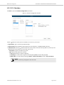
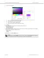
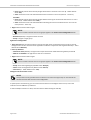
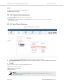
4. Create a New Project from a Template
1. Open Intesis MAPS.
2. Click Create New Project in the Geng started menu on the le.
You can create a project from scratch using a template. To nd the appropriate template, lter the search
by:
• Clicking on the protocol logos, depending on the desired applicaon.
• Typing the order code IN703DAL0640000 in the Order Code eld.
NOTE
The order code is printed on the silver label placed on the gateway's right side.
• Looking for the Project Name IN-BAC-DALI-64 or IN-MBS-DALI-64 on the list.
Figure 1. Three possibilies for the template selecon
3. Select the desired template.
4. Click Next or double-click the template on the list.
NOTE
Templates are just examples of integraon. Depending on the type of integraon, you may have to
modify some parameters.
IMPORTANT
Don't forget to save your project on your computer before exing Intesis MAPS. To do so, go to
Project → Save or Save As. Later on, you can load the project to Intesis MAPS and connue with the
conguraon.
INTESIS MAPS: CONFIGURATION AND MONITORING SOFTWARE Create a New Project from a Template
Page 4 of 60 INTESIS MAPS USER MANUAL Version 1.0.2

Create a New Project from a Template INTESIS MAPS: CONFIGURATION AND MONITORING SOFTWARE
INTESIS MAPS USER MANUAL Version 1.0.2 Page 5 of 60

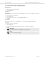
5. Main Menu Overview
Figure 2. Intesis MAPS main menu
The following secons provide an overview of the ve tabs that compose the Intesis MAPS main menu. Through
these opons, you will congure both the gateway and your project, and monitor that everything works ne
using the Diagnosc tab.
INTESIS MAPS: CONFIGURATION AND MONITORING SOFTWARE Main Menu Overview
Page 6 of 60 INTESIS MAPS USER MANUAL Version 1.0.2

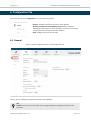
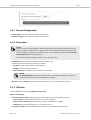
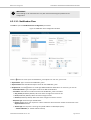
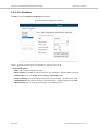
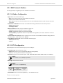
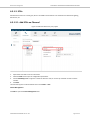
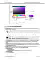
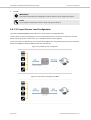
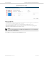
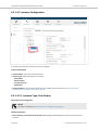
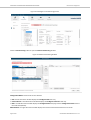
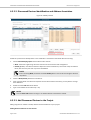
6. Conguraon Tab
Find on the le side of the Conguraon tab a menu with three opons:
•General: Congure the general parameters of the gateway.
•Building management system (BMS) protocol: Modbus or BACnet,
depending on your project's current applicaon. In the case of the image
on the le, the control system is based on Modbus.
•DALI: Congure the parameters for DALI.
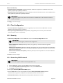
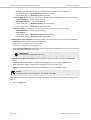
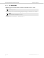
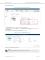
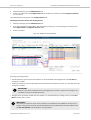
6.1. General
Figure 3. General conguraon menu on the Conguraon tab
Use this menu to congure some general parameters of the gateway.
TIP
Toolp: Hover the cursor over a eld, and a message will appear indicang the purpose of the
parameter.
Conguraon Tab INTESIS MAPS: CONFIGURATION AND MONITORING SOFTWARE
INTESIS MAPS USER MANUAL Version 1.0.2 Page 7 of 60

6.1.1. General Conguraon
•Gateway Name: Type a descripve name for your gateway.
•Project Descripon: Type a short descripon of your project.
6.1.2. Connecon
NOTE
When commissioning the gateway for the rst me, DHCP will be enabled for 30 seconds. During
that me, if there is a DHCP server, an IP address will be automacally assigned to the gateway. If
there is no DHCP, you can type an IP address of your choice. Aer that me, the default IP address
192.168.100.246 will be automacally set.
You can nd this default IP address wrien in the installaon sheet.
•Enable DHCP: Use this opon for networks that have a DHCP server.
Uncheck this opon to unlock the following parameters:
–IP Address: Assign a xed IP address for the gateway.
–Net Mask: Set the gateway IP netmask.
–Default Gateway: Set the default route assigned to the gateway.
NOTE
The Default Gateway parameter is oponal, but you must dene the gateway route when a
connecon to the internet or to other networks is needed.
•Password: Click the Change buon and follow the instrucons to set a password for the gateway.
6.1.3. USB Host
Click the Edit buon to open the USB Mode Conguraon.
Buon A Funconality
•Auto Capture logs in USB (enabled by default): Capture logs by pressing the gateway's buon A.
–Capture Spons (enabled by default): Spontaneous values are logged.
–Capture Communicaon (enabled by default): Protocol communicaon is logged.
–Debug Level: Choose the debug level (0 .. 255. Default value: 1).
•Save project in USB (enabled by default): Save the project to the USB together with the logs.
INTESIS MAPS: CONFIGURATION AND MONITORING SOFTWARE General
Page 8 of 60 INTESIS MAPS USER MANUAL Version 1.0.2

Buon B Funconality
•Download project to the gateway (enabled by default): Download a project from a USB ash drive to the
gateway by pressing the gateway's buon B.
•Download Firmware to the gateway (enabled by default): Download a rmware version from a USB ash drive
to the gateway by pressing the gateway's buon B.
IMPORTANT
The gateway's USB port only admits the connecon of a USB ash drive. No external hard disks or
similar are allowed.
Click Apply to save the changes.
6.1.4. Time Conguraon
•Set current PC me to the gateway: Connect the gateway to your PC and click the Set buon to set the
gateway's clock with your PC's current me.
•Time sync on project download (disabled by default): The gateway's clock is set to your PC me when
downloading the project to the gateway.
6.1.5. Security
•Edit Security Conguraon: Click the Edit buon to open the Security Conguraon window.
IMPORTANT
We recommend keeping the predetermined conguraon.
–Disable UPD Discover Service (disabled by default): The gateway is not discoverable through UDP
communicaon.
–Disable TCP Console Service (disabled by default): The gateway stops communicang with the conguraon
and diagnosc soware through TCP. This only applies to gateways supporng connecon to the PC via both
Ethernet and console ports.
–Disable HTTPS Cercates Auto Update (enabled by default): Automac updates for the HTTPS cercates
are not allowed.
Click Save to save the changes.
6.1.6. Secondary BMS Protocol
IMPORTANT
This funcon applies to BACnet to DALI applicaons only.
1. Click the Edit buon to add a secondary BMS protocol based on Modbus.
2. On the Secondary BMS Protocol Management window, select Modbus Slave.
3. Click Apply to save the changes.
The new opon Secondary BMS Protocol MAP appears.
• Click the View buon on this second opon to view the Extra protocol Map Summary window.
The table lists the signals for the BMS, the secondary BMS, and the device protocols.
•View Internal Columns (enabled by default): Hide/show the BACnet Server column.
General INTESIS MAPS: CONFIGURATION AND MONITORING SOFTWARE
INTESIS MAPS USER MANUAL Version 1.0.2 Page 9 of 60

•View External Columns (enabled by default): Hide/show the DALI column.
•View Secondary BMS Protocol Columns (enabled by default): Hide/show the Modbus Master column.
NOTE
Click the Export buon to save an Excel copy of the table on your computer.
The menu on the le now shows Modbus Slave (MBS):
Conguraon parameters for the secondary BMS:
Modbus Conguraon
•Type: TCP (RTU opon is not allowed).
•Byte Order 32 bits registers. Choose between:
–Big Endian (default value)
–Lile Endian
–Word Inv BE (word inverted Big Endian)
–Word Inv LE (word inverted Lile Endian)
•Nocaon on MB Write. Select when the Modbus write nocaon will be sent to the device protocol:
–Always
–On Change of Value (default value)
•Select Modbus register base. Choose between:
–0 based (default value)
–1 based
TCP Conguraon
•Port: Set the port for communicaon between the gateway and the Modbus TCP system.
NOTE
The default port is 502.
•Keep Alive: Set the me in minutes before sending a keep-alive message (1 to 1440. Default value: 10 min).
NOTE
Set the parameter to 0 to disable this funcon.
•Slave Number: Set the Modbus Slave Address (1 to 255. Default value: 1).
MBS Summary
•View MBS Extra Protocol Summary: Click the View buon to open the Extra protocol Map Summary window.
INTESIS MAPS: CONFIGURATION AND MONITORING SOFTWARE General
Page 10 of 60 INTESIS MAPS USER MANUAL Version 1.0.2

NOTE
See above for details.
•Select registers format. Choose between:
–16 bits unsigned (default value)
–32 bits oat
6.1.7. Wiring Diagram
•Check Gateway's Wiring Diagram: Click the View buon to open the schemac image on how to wire the
gateway.
6.2. BMS Protocol Conguraon
6.2.1. BMS Protocol: BACnet
For this applicaon, the gateway acts like a BACnet server device.
BMS Protocol Conguraon INTESIS MAPS: CONFIGURATION AND MONITORING SOFTWARE
INTESIS MAPS USER MANUAL Version 1.0.2 Page 11 of 60

6.2.1.1. BACnet Server General Conguraon
•Device Name: Type a descripve name for your gateway.
•Device Instance: Set the BACnet device object instance property. This is a unique idener for the gateway
inside a single BACnet network segment (0 to 4194302. Default value: 246).
•Password: Click the Change buon and follow the instrucons to set a password for the gateway.
•Objects Informaon: Click Show to see a table with the type of objects available.
•Disable BACnet password (not recommended) (parameter disabled by default): Disable the BACnet password.
IMPORTANT
Keep the BACnet password enabled to ensure the security of the gateway and the installaon.
6.2.1.2. Gateway Mode
•Mode: Select the communicaon type.
–IP (default value): IP communicaon over Ethernet.
•UDP Port: Select the UDP port for the BACnet/IP communicaon.
NOTE
The UDP port is set to 47808 (BAC0 in hexadecimal) by default.
•Network Role (disabled by default): Dene the gateway behavior regarding other network elements.
IMPORTANT
If you are unfamiliar with these opons, please leave the parameter as Disabled to avoid
issues with the BACnet communicaon/conguraon.
–Disabled: The gateway provides no special service regarding network communicaon or sengs.
–Foreign Device: The gateway acts as a foreign device from the BACnet network point of view.
–BBMD: The gateway acts as a BBMD in the BACnet network.
–MS/TP: Serial communicaon over the EIA-485 bus.
•Baudrate: Select the communicaon speed: Auto, 9600, 19200, 38400, 57600, 76800, or 115200 bps.
NOTE
The baudrate is set to Auto by default.
•Max. Masters: Set the highest master MAC address in the MS/TP network (1 .. 127. Default value: 127).
•Max. Info Frames: Set the maximum number of messages that can be sent onto MS/TP network per
token pass (1 .. 100. Default value: 1).
•MAC Address: Set the MAC address of the gateway in the MS/TP network (0 .. 127. Default value: 1).
•Edit MSTP Timeouts: Click Edit to open the MSTP Timeouts Conguraon window.
–PFM Timeout: Set the polling for master meout in milliseconds (20 .. 100 ms. Default value: 60 ms).
–TP Timeout: Set the token passing meout in milliseconds (20 .. 100 ms. Default value: 60 ms).
6.2.1.3. BACnet Advanced Conguraon
Show Advanced Conguraon: Open advanced conguraon parameters (disabled by default).
INTESIS MAPS: CONFIGURATION AND MONITORING SOFTWARE BMS Protocol Conguraon
Page 12 of 60 INTESIS MAPS USER MANUAL Version 1.0.2

IMPORTANT
These sengs are for advanced users only. We recommend leaving the predetermined
conguraon.
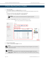
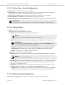
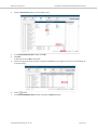
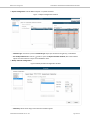
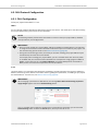
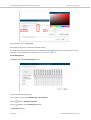
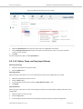
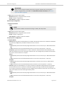
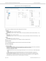
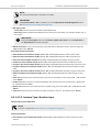
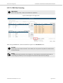
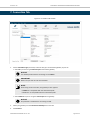
6.2.1.3.1. Nocaon Class
Click Edit to open the Nocaon Class Conguraon parameters.
Figure 4. Nocaon Class Conguraon window
Click the buon to create up to ten Nocaon_Class objects. For each one, you can set:
•Object Name: Type a name for the Nocaon_Class.
•Object Instance: Sets the BACnet object instance for the Nocaon_Class.
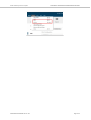
•Recipient List: Click the buon to create eight dierent BACnet desnaons. For each one, you can set:
–Desnaon Name: Type a descripve name for the BACnet desnaon.
–Transions: Select which transions will force this Nocaon_Class to be acve:
•O_normal (disabled by default): When the status changes from o to normal.
•Fault (disabled by default): When the status changes to fault.
•Normal (disabled by default): When the status changes from fault to normal.
–Recipient Type: Select the type of desnaon:
•Device (default value): The recipient is a device. Select the device instance number for this device in the
Object Instance text box.
•Address (IP): The recipient is set using the specic address on BACnet/IP. Specify:
–Network Number (0 .. 65535. Default value: 0).
BMS Protocol Conguraon INTESIS MAPS: CONFIGURATION AND MONITORING SOFTWARE
INTESIS MAPS USER MANUAL Version 1.0.2 Page 13 of 60

–IP address (192.168.100.10 by default) and Port (47808 by default) for the desnaon.
– Set the desnaon as a Global Broadcast (disabled by default).
– Set the desnaon as a Broadcast (disabled by default).
•Address (MS/TP): The recipient is set using the specic address on BACnet MS/TP. You'll have to specify:
–Network Number (0 .. 65535. Default value: 0).
–MS/TP MAC Address (0 .. 255. Default value: 0).
– Set the desnaon as a Global Broadcast (disabled by default).
– Set the desnaon as a Broadcast (disabled by default).
•Address (Other): The recipient is set using another type of address. You'll have to specify:
–Network Number (0 .. 65535. Default value: 0).
–Other Address.
– Set the desnaon as a Global Broadcast (disabled by default).
– Set the desnaon as a Broadcast (disabled by default).
•BACDesnaon Advanced Opons (disabled by default): Check this opon to show some advanced opons.
–Valid days: Sets the days for receiving the nocaon.
–From: Sets the starng point for the valid period.
–To: Sets the ending point for the valid period.
–Issue Conrmed Nocaons (disabled by default): Determines if nocaon events are sent as Conrmed
or Unconrmed to the BACnet desnaon.
IMPORTANT
Sending them as Conrmed requires Ack.
•Nocaon Class Advanced Opons (disabled by default): Check this opon to show the Ack Required
opons.
–O_Normal (disabled by default): Enable the acknowledgment for the TO_OFF_NORMAL event.
–Fault (disabled by default): Enable the acknowledgment for the TO_FAULT event.
–Normal (disabled by default): Enable the acknowledgment for the TO_NORMAL event.
NOTE
Set the priority for each parameter (0 .. 255. Default value: 140).
Once you have created and congured the needed Nocaon_Class objects, the next step is to assign them to
signals:
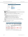
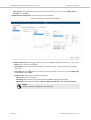
1. Go to the Signals tab.
INTESIS MAPS: CONFIGURATION AND MONITORING SOFTWARE BMS Protocol Conguraon
Page 14 of 60 INTESIS MAPS USER MANUAL Version 1.0.2

2. Click the Edit Columns buon from the boom menu.
3. In the Select Visible Columns window, check NC.
4. Click Save.
A new column named NC is now visible.
5. Look for the signal to which you want to assign the Nocaon_Class object and click the corresponding cell
in the NC column.
6. Click the buon.
7. In the Select Nocaon Class window, uncheck the Empty parameter.
BMS Protocol Conguraon INTESIS MAPS: CONFIGURATION AND MONITORING SOFTWARE
INTESIS MAPS USER MANUAL Version 1.0.2 Page 15 of 60

8. Use the dropdown menu to select the Nocaon_Class object.
9. Set the rest of the parameters:
NOTE
These parameters vary depending on the signal type.
•Nofy Type: Choose if the nocaon is sent as an Alarm (default) or an Event.
•Time Delay: Set the me in seconds before launching the nocaon (0 .. 65535. Default value: 0
seconds).
•Event Enable: Click in the eld to enable/disable the following opons:
–TO_OFF_NORMAL (enabled by default): Enable/disable the TO_OFF_NORMAL event.
–TO_FAULT (enabled by default): Enable/disable the TO_FAULT event.
–TO_NORMAL (enabled by default): Enable/disable the TO_NORMAL event.
•Feedback Value: Choose if the feedback value is Acve or Inacve (default).
•High Limit (Disabled by default): Enable this parameter to set the high limit for the nocaon.
•Low Limit (Disabled by default): Enable this parameter to set the low limit for the nocaon (0.00 ..
999.00).
•Deadband: Set the deadband for the nocaon.
10. Click Save to save the changes.
Once assigned, the instance number of the Nocaon_Class object appears in the NC column.
INTESIS MAPS: CONFIGURATION AND MONITORING SOFTWARE BMS Protocol Conguraon
Page 16 of 60 INTESIS MAPS USER MANUAL Version 1.0.2
Page is loading ...
Page is loading ...
Page is loading ...
Page is loading ...
Page is loading ...
Page is loading ...
Page is loading ...
Page is loading ...
Page is loading ...
Page is loading ...
Page is loading ...
Page is loading ...
Page is loading ...
Page is loading ...
Page is loading ...
Page is loading ...
Page is loading ...
Page is loading ...
Page is loading ...
Page is loading ...
Page is loading ...
Page is loading ...
Page is loading ...
Page is loading ...
Page is loading ...
Page is loading ...
Page is loading ...
Page is loading ...
Page is loading ...
Page is loading ...
Page is loading ...
Page is loading ...
Page is loading ...
Page is loading ...
Page is loading ...
Page is loading ...
Page is loading ...
Page is loading ...
Page is loading ...
Page is loading ...
Page is loading ...
Page is loading ...
Page is loading ...
Page is loading ...
-
 1
1
-
 2
2
-
 3
3
-
 4
4
-
 5
5
-
 6
6
-
 7
7
-
 8
8
-
 9
9
-
 10
10
-
 11
11
-
 12
12
-
 13
13
-
 14
14
-
 15
15
-
 16
16
-
 17
17
-
 18
18
-
 19
19
-
 20
20
-
 21
21
-
 22
22
-
 23
23
-
 24
24
-
 25
25
-
 26
26
-
 27
27
-
 28
28
-
 29
29
-
 30
30
-
 31
31
-
 32
32
-
 33
33
-
 34
34
-
 35
35
-
 36
36
-
 37
37
-
 38
38
-
 39
39
-
 40
40
-
 41
41
-
 42
42
-
 43
43
-
 44
44
-
 45
45
-
 46
46
-
 47
47
-
 48
48
-
 49
49
-
 50
50
-
 51
51
-
 52
52
-
 53
53
-
 54
54
-
 55
55
-
 56
56
-
 57
57
-
 58
58
-
 59
59
-
 60
60
-
 61
61
-
 62
62
-
 63
63
-
 64
64


Ask a question and I''ll find the answer in the document
Finding information in a document is now easier with AI
Related papers
-
Intesis IN770AIR00SO000 User manual
-
-
-
-
Intesis IN700-485 Series User manual
-
-
-
-
-
Intesis INBACMBM1000000 User manual
Other documents
-
SKYDANCE DA-4S User manual
-
Sunricher SR-2412-Scenes-B User manual
-
 Kaysun BMS Controller K05 BACNET 1 User manual
-
IntesisBox IBMBSMEB0100000 User manual
-
Hisense IntesisBox Modbus Server VRF Air Conditioning User manual
-
-
-
Anybus AB9900 User manual
-
-
