Page is loading ...

EnergyMetering
ZENNER International Römerstadt 4 Tel: +49 681 99 676-0
GmbH & Co. KG D-66121 Saarbrücken Fax: +49 681 99 676-100
1.
Clean the transparent cover ensuring that no dirt en-
ters into the screw drill holes. Next, position the reed
switch ring so that the window sits directly over the me-
ter. When pushed into place, an audible “click“ should
be heard.
2.
The reed switch ring can only be detached using a
screwdriver.
3.
Seal the slot against tampering by afxing the provided
sticker. A magnetic shield is not necessary for the 100
l/Impuls model.
Secure both screws (M4x16) and seal both screws
against tampering by afxing the provided sticker. A
magnetic shield is not necessary for the 100 l/impuls
model.
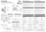
Reed switch installation 100 I/Impuls
ETK-I-N/MTK-I-N
47
1k
Y
ellow / Gelb
White / Weiß
Green / Grün
Brown / Braun
Puls Ausgangsschalter
Pulse Output Switch
Manipulationsschalter
Tamper Switch
47
1k
White / Weiß
Brown / Braun
Puls Ausgangsschalter
Pulse Output Switch
10/100 l/Impuls
The circuit diagram and colour code for the wires is as
shown below. The brown and white wires are normally
connected to the remote reading equipment. Unused
wires should either be terminated in a junction box or
suitably sealed against water ingress when used out-
doors.
47
1k
Y
ellow / Gelb
White / Weiß
Green / Grün
Brown / Braun
Puls Ausgangsschalter
Pulse Output Switch
Manipulationsschalter
Tamper Switch
47
1k
White / Weiß
Brown / Braun
Puls Ausgangsschalter
Pulse Output Switch
Wire color code
Maximum Switched Voltage: 180 VDC
Maximum Switched Current: 500 mA
Maximum Switched Power 10 W
/