Page is loading ...

1 2
Bei der Verwendung eines Optogebers mit dem Messumformer „Adamczewski AD-FM600“ ist es er-
forderlich den mitgelieferten Pull-Up Widerstand von 1,5kOhm aufzuschalten. Der Widerstand muss
bei 1-Kanal Betrieb zwischen die Klemmen S+ (1) Braun und E+ (2) Grün aufgeschaltet werden. Im
Falle eines 2-Kanal-Betriebs, muss ein weiterer Widerstand auf die Klemmen 6 und 7 aufgeschaltet
werden.
Wenn der Optogeber mit einem „Diehl BR 520.11“ Messumformer betrieben wird, ist kein Pull-up
Widerstand erforderlich.
Allgemeine Hinweise
■ Zwei Schrauben am Deckel herausdrehen und
den Deckel abnehmen.
■ Sensor in die entsprechende Führung von
oben einschieben.
• Das Kabel des Reedkontaktgebers muss
dabei nach „unten“ zeigen.
• Das Kabel des Optogebers muss dabei
nach „oben“ zeigen.
■ Zur Kabelzugentlastung das Sensorkabel
durch die Kabelausführung der Haube führen
und Haube wieder montieren.
■ Haube ggf. gegen unbefugte Demontage mit
beiliegendem Plombendraht und Schnapp-
plombe sichern.
Reedkontaktgeber
Typ: Potentialfreier Reed-Kontaktgeber, Schließer
Ausführung: In transparentem Gehäuse (vergossen)
Schutzklasse: IP 68
Kabellänge: 2m
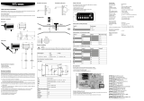
Schaltplan
Optogeber
Typ: Optoelektronischer Infrarot-Refl ex-Impulsgeber
Ausführung: In transparentem Gehäuse (vergossen)
Schutzklasse: IP 68
Kabellänge: 2m
Technische Daten Optogeber
Kabelausführung 3-Leiter-Kabel LiYY 3 x 0,25 mm²
Aderfarbe Braun = Plus; Weiß = GND;
Grün = Impulsausgang
Betriebsspannung Us = 5 bis 24V DC
Stromverbrauch Is < 30 mA (Io = 0 mA)
Ausgangstyp NPC OC (Open Collector)
Technische Änderungen vorbehalten. Für etwaige Irrtümer und Druckfehler übernehmen wir keine Haftung. SAP 158285_ZRI_180810_DE_EN
Schaltplan
Die neuesten Informationen zu diesem Produkt können unter www.zenner.de abgerufen werden.
Technische Daten Reedkontaktgeber
Kabelausführung 2-Leiter-Kabel, YTLY 2 x 0,14 mm²
Aderfarbe Braun, Weiß (verpolungssicher)
Max. Schaltspannung Us < 24V
Max. Strombelastung Is = 5 bis 15mA (max 50mA)
Schutzwiderstand Ohne
Impulsdauer Durchfl ussabhängig
Installationsanleitung
Reedkontaktgeber und Optogeber (WPV-N / WB-N / ETK-N-C)
Deutsch
ZENNER International GmbH & Co. KG
Römerstadt 6 | 66121 Saarbrücken | Germany
E-Mail info@zenner.de
Internet www.zenner.de
Telefon +49 681 99 676-30
Telefax +49 681 99 676-3100

3 4
Subject to modifi cations and errors excepted. Any liability for misprints excluded.
General notes
■ Unscrew the two screws on the hood and re-
move the hood.
■ Insert the sensor from above into the corres-
ponding slot.
• The cable of the Reed switch must show
„down“.
• The cable for the Optical sensor must show
“upwards”.
■ For cable relief, lead the sensor cable through
the cable opening of the hood and reinstall the
hood.
■ If necessary, secure the hood against unau-
thorized disassembly with the enclosed seal
wire and snap seal.
Reed switch
Type: Potential-free Reed switch
Model: Transparent housing (encapsulated)
Protection class: IP 68
Cable length: 2m
circuit diagram
Optical sensor
Type: Optical sensor (Infrared refl ex pulse sensor)
Model: Transparent housing (encapsulated)
Protection class: IP 68
Cable length: 2m
Technical specifi cations Optical sensor
Cable output 3-wire-cable LiYY 3 x 0,25 mm²
Colour of conductor Brown = Plus; White = GND;
Green = Pulse output
Operating voltage Us = 5 to 24V DC
Power consumption Is < 30 mA (Io = 0 mA)
Output NPC OC (Open Collector) circuit diagram
The latest information about this product can be accessed or downloaded from www.zenner.com
Technical specifi cations Reed switch
Cable output 2-wire cable, YTLY 2 x 0,14 mm²
Colour of conductor Brown, White (polarity protected)
Max. switching voltage Us < 24V
Max. current load Is = 5 to 15mA (max 50mA)
Protective resistor Without
Pulse duration Flow-dependent
Installation instructions
for Reed switch and Optical Sensor (WPV-N / WB-N / ETK-N-C)
When using an opto-sensor with the transducer „Adamczewski AD-FM600“ it is necessary to connect
the provided pull-up resistance of 1.5 kOhm. The resistance must be connected for 1-channel opera-
tion between the terminals S+ (1) brown and E+ (2) green. For 2-channel operation further resistance
must be connected on terminals 6 and 7.
If the opto-sensor is operated with a „Diehl BR 520.11“ transducer then no pull-up resistance is ne-
cessary.
English
ZENNER International GmbH & Co. KG
Römerstadt 6 | 66121 Saarbrücken | Germany
E-Mail info@zenner.com
Internet www.zenner.com
Phone +49 681 99 676-30
Telefax +49 681 99 676-3100
/