Page is loading ...

ECP-2704T Installation Guide
1. Other than automatic IP setting (i.e. DHCP), set the IP address on the
cameras following the camera manufacturer’s manual.
2. Connect BNC connectors of coaxial cable to each ECP-2704T & 2701.
3. Connect 57V DC power to ECP-2701 first and the to AC outlet.
[It is recommended to apply an additional power to ECP-2704T for
stable PoE output to camera]
* The total distance may vary with the type and condition of cable.
and power consumption of the PoE camera.(For example of 7W camera,
one 57Vdc power can supply up to 300m of RG-6.)
* Do Not dismantle UTP(LAN) cable nor divide it by four. It may cause
serious interference between cables so that data transmission may not
be successful.
4. When they are connected without any problem, PWR/BNC Join/
Quality PWR LED are on.
5. Fix up ECP-2704T and ECP-2701.
6. Connect the UTP(LAN) cable between ECP-2701 and NVR first and
connect 4 cameras to ECP-2704T.
[Ping test is recommended to confirm the whole network connection]
7. Check the video image on the monitor.
Product Installation Guide
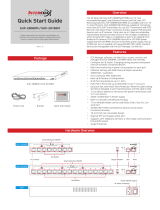
Hardware Overview
Product Application
DC Power Jack BNC
LED Indicator Join Button
RJ45
Package Contents
ECP-2704T Installation Guide
Guide
Front
Back
57V DC
Optional
AC/DC Adapter (57V)
AC/DC Adapter (57V)

Please install the device following the installation guide.
Do not touch the device and cable with wet hands.
Keep away from moisture and shock.
Do not install near any heat sources such as radiators, heat registers,
stoves or other apparatus that produce heat.
Indoor use only.
Do not use for other purposes.
(i.e. Do not connect analog camera to BNC connector on the product.)
Do not disassemble or modify this device.
Do not put any sticker or paint on device.
If device is defective or malfunctioning, please unplug the power
adapter immediately and contact dealer or service center.
Use only rated 57VDC power adapter specified by the
manufacturer. Connect DC power to ECP-2701(or ECP-2704T) first
and then to AC outlet.
Caution
All ECP products have the same network password on factory default
to support plug & play between ECP Series.
In case of multiple 1:1 connections, it is possible to avoid network
interference by setting password of each group.
1. Basic connection
Connect devices with coaxial cable and apply power.
2. Unjoin: remove the password
Push the join button of one of the devices for 11 seconds
BNC Join LED turns off.
Push the join button of other end device for 11 seconds.
3. Join: Create new password
After unjoining, push the join button of one of the device for 2 seconds.
PWR LED turns off and BNC Join LED turns on.
Push the join button of other end device for 2 seconds.
After PWR LED is on, BNC Join LED of both devices flickers and
network is working again
4. Repeat above mentioned steps(1~3) for other groups.
(Caution) new and random password is automatically assigned and
it can not be restored to the factory default password.
Group A
Network Password Change
This device has passed the quality control and product inspection.
Please install and use according to the installation guide.
The warranty period for this product is 24 months from the date of
purchase.
Any damages or breakage from user’s abuse, accident, modification
or natural disasters will not be covered by manufacturer’s warranty.
Warranty
Customer Service
Please visit the below website for more detail informaton.
http://www.intercoax.com
Macufacturer: Intercoax Co.,Ltd
TEL : +82-31-365-3133~4
E-mail : info@intercoax.com
Indicator Color Status
BNC Join ECP-Product Linked
Data
PoE
Port1~Port4
Good Link Quality
Bad Link Quality
Bad Power Quality
(* Additional power required)
Data Act - Flickering
Data Act - Flickering
PoE Output - On
PWR
Quality
LINK
PWR
57V DC Powered
LED Indicators
Good Power Quality
Group C
Group B
AC/DC Adapter (57V)
/