12
Chapter 5: Configuring the Wireless-N Broadband Router
The Setup Tab - Basic Setup
Wireless-N Broadband Router
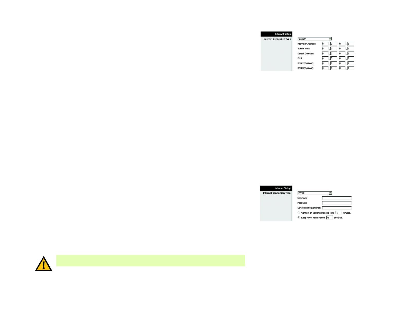
Static IP
If you are required to use a permanent IP address, then select Static IP.
Internet IP Address. This is the IP address that the Router has, when seen from the Internet. Your ISP will
provide you with the IP address you need to specify here.
Subnet Mask. This is the Router’s Subnet Mask, as seen by external users on the Internet (including your
ISP). Your ISP will provide you with the Subnet Mask.
Default Gateway. Your ISP will provide you with the Default Gateway Address.
DNS 1-3. Your ISP will provide you with at least one DNS (Domain Name System) Server IP Address.
PPPoE
Some DSL-based ISPs use PPPoE (Point-to-Point Protocol over Ethernet) to establish Internet connections for
end-users. If you use a DSL line, check with your ISP to see if they use PPPoE. If they do, you will have to
enable it.
User Name and Password. Enter the User Name and Password provided by your ISP.
Service Name. If provided by your ISP, enter the Service Name.
Connect on Demand and Max Idle Time. You can configure the Router to cut the Internet connection after it
has been inactive for a specific period of time (Max Idle Time). If your Internet connection has been
terminated due to inactivity, Connect on Demand enables the Router to automatically re-establish your
connection as soon as you attempt to access the Internet again. To use Connect on Demand, click the radio
button. If you want your Internet connection to remain on at all times, enter 0 in the Max Idle Time field.
Otherwise, enter the number of minutes you want to have elapsed before your Internet access disconnects.
Keep Alive and Redial Period. This option keeps your Internet access connected indefinitely, even when it
sits idle. If you select this option, the Router will periodically check your Internet connection. If the connection
is down, then the Router will automatically re-establish the connection. To use this option, click the radio
button next to Keep Alive. The default Redial Period is 30 seconds.
Click the Save Settings button. Then click the Status tab, and click the Connect button.
Figure 5-3: Static IP
Figure 5-4: PPPoE
IMPORTANT: For DSL users, if you need to enable PPPoE support, remember to remove any
PPPoE applications that are installed on your PCs.
static ip address: a fixed address
assigned to a computer or device
connected to a network.
pppoe: a type of broadband connection that
provides authentication (username and
password) in addition to data transport
subnet mask: an address code that
determines the size of the network
default gateway: a device that forwards
Internet traffic from your local area network


