Da-Lite 35201 Installation guide
- Category
- Projection screens
- Type
- Installation guide
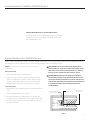
Da-Lite 35201 is a motorized retractable projection screen designed for boardroom and classroom use. It features a durable, matte white fabric that provides a wide viewing angle and excellent color reproduction, making it suitable for presentations, videos, and movies. The screen is easy to install and operate, with a simple wall-mounted switch or optional remote control. The 35201 also has a built-in limit switch that automatically stops the screen at the fully opened and closed positions, ensuring a long lifespan and reliable operation.
Da-Lite 35201 is a motorized retractable projection screen designed for boardroom and classroom use. It features a durable, matte white fabric that provides a wide viewing angle and excellent color reproduction, making it suitable for presentations, videos, and movies. The screen is easy to install and operate, with a simple wall-mounted switch or optional remote control. The 35201 also has a built-in limit switch that automatically stops the screen at the fully opened and closed positions, ensuring a long lifespan and reliable operation.


-
 1
1
-
 2
2
-
 3
3
-
 4
4
-
 5
5
-
 6
6
-
 7
7
-
 8
8
-
 9
9
-
 10
10


Da-Lite 35201 Installation guide
- Category
- Projection screens
- Type
- Installation guide
Da-Lite 35201 is a motorized retractable projection screen designed for boardroom and classroom use. It features a durable, matte white fabric that provides a wide viewing angle and excellent color reproduction, making it suitable for presentations, videos, and movies. The screen is easy to install and operate, with a simple wall-mounted switch or optional remote control. The 35201 also has a built-in limit switch that automatically stops the screen at the fully opened and closed positions, ensuring a long lifespan and reliable operation.
Ask a question and I''ll find the answer in the document
Finding information in a document is now easier with AI
Related papers
-
Da-Lite Boardroom ElEctrol Owner's manual
-
Da-Lite 79936 User manual
-
Da-Lite 21777 User manual
-
-
-
-
-
-
-
Other documents
-
Delta RS1000W User manual
-
Glacier Bay 82055 Installation guide
-
Epson 100in. Da-Lite IDEA Screen for Projection and Dry-erase Installation guide
-
Infocus SC-PUW-73 Datasheet
-
Projecta Tabscreen Electrol, High Contrast Cinema Vision Installation guide
-
-
Displays2go DL10F Assembly Instructions
-
Draper 116306 Operating instructions
-
Raco 8977 Installation guide
-
Unbranded 1616059 Installation guide