
AC Power
For Business-Critical Continuity™
Liebert
®
GXT3
™
UPS 230V 700VA-3000VA
User Manual


i
TABLE OF CONTENTS
IMPORTANT SAFETY PRECAUTIONS . . . . . . . . . . . . . . . . . . . . . . . . . . . . . . . . . . . . . . . . . . . . . . . .1
SAVE THESE INSTRUCTIONS . . . . . . . . . . . . . . . . . . . . . . . . . . . . . . . . . . . . . . . . . . . . . . . . . . . . .1
GLOSSARY OF SYMBOLS . . . . . . . . . . . . . . . . . . . . . . . . . . . . . . . . . . . . . . . . . . . . . . . . . . . . . . . .3
1.0 PRODUCT DESCRIPTION . . . . . . . . . . . . . . . . . . . . . . . . . . . . . . . . . . . . . . . . . . . . . . . . . . .4
1.1 Features . . . . . . . . . . . . . . . . . . . . . . . . . . . . . . . . . . . . . . . . . . . . . . . . . . . . . . . . . . . . . . . . . . . 4
1.2 Available Models . . . . . . . . . . . . . . . . . . . . . . . . . . . . . . . . . . . . . . . . . . . . . . . . . . . . . . . . . . . . 4
1.3 Appearance and Components . . . . . . . . . . . . . . . . . . . . . . . . . . . . . . . . . . . . . . . . . . . . . . . . . . 5
1.3.1 Appearance . . . . . . . . . . . . . . . . . . . . . . . . . . . . . . . . . . . . . . . . . . . . . . . . . . . . . . . . . . . . . . . . . . 5
1.3.2 Rear Panel Features. . . . . . . . . . . . . . . . . . . . . . . . . . . . . . . . . . . . . . . . . . . . . . . . . . . . . . . . . . . 5
1.4 Major Components . . . . . . . . . . . . . . . . . . . . . . . . . . . . . . . . . . . . . . . . . . . . . . . . . . . . . . . . . . . 6
1.5 Operating Mode . . . . . . . . . . . . . . . . . . . . . . . . . . . . . . . . . . . . . . . . . . . . . . . . . . . . . . . . . . . . . 7
1.5.1 Mains (AC) Mode . . . . . . . . . . . . . . . . . . . . . . . . . . . . . . . . . . . . . . . . . . . . . . . . . . . . . . . . . . . . . 7
1.5.2 Manual Bypass Mode . . . . . . . . . . . . . . . . . . . . . . . . . . . . . . . . . . . . . . . . . . . . . . . . . . . . . . . . . . 8
1.5.3 Battery Mode . . . . . . . . . . . . . . . . . . . . . . . . . . . . . . . . . . . . . . . . . . . . . . . . . . . . . . . . . . . . . . . . 8
1.5.4 Battery Recharge Mode . . . . . . . . . . . . . . . . . . . . . . . . . . . . . . . . . . . . . . . . . . . . . . . . . . . . . . . . 8
1.5.5 Frequency Converter Mode . . . . . . . . . . . . . . . . . . . . . . . . . . . . . . . . . . . . . . . . . . . . . . . . . . . . . 8
2.0 INSTALLATION . . . . . . . . . . . . . . . . . . . . . . . . . . . . . . . . . . . . . . . . . . . . . . . . . . . . . . . . . .9
2.1 Unpacking and Inspection . . . . . . . . . . . . . . . . . . . . . . . . . . . . . . . . . . . . . . . . . . . . . . . . . . . . . 9
2.2 What’s Included . . . . . . . . . . . . . . . . . . . . . . . . . . . . . . . . . . . . . . . . . . . . . . . . . . . . . . . . . . . . . 9
2.3 Preparation for Installation . . . . . . . . . . . . . . . . . . . . . . . . . . . . . . . . . . . . . . . . . . . . . . . . . . . . 9
2.3.1 Installation Environment. . . . . . . . . . . . . . . . . . . . . . . . . . . . . . . . . . . . . . . . . . . . . . . . . . . . . . . 9
2.4 Mechanical Installation . . . . . . . . . . . . . . . . . . . . . . . . . . . . . . . . . . . . . . . . . . . . . . . . . . . . . . 10
2.4.1 Tower Installation . . . . . . . . . . . . . . . . . . . . . . . . . . . . . . . . . . . . . . . . . . . . . . . . . . . . . . . . . . . 10
2.4.2 Rack Installation . . . . . . . . . . . . . . . . . . . . . . . . . . . . . . . . . . . . . . . . . . . . . . . . . . . . . . . . . . . . 11
2.5 Cable Connection . . . . . . . . . . . . . . . . . . . . . . . . . . . . . . . . . . . . . . . . . . . . . . . . . . . . . . . . . . . 14
2.5.1 Connecting to AC Mains and Loads . . . . . . . . . . . . . . . . . . . . . . . . . . . . . . . . . . . . . . . . . . . . . 15
2.5.2 Connecting Battery Cables . . . . . . . . . . . . . . . . . . . . . . . . . . . . . . . . . . . . . . . . . . . . . . . . . . . . 15
2.6 Connecting Communication Cables. . . . . . . . . . . . . . . . . . . . . . . . . . . . . . . . . . . . . . . . . . . . . 16
2.6.1 Connecting USB Communication Cables . . . . . . . . . . . . . . . . . . . . . . . . . . . . . . . . . . . . . . . . . 16
2.6.2 Installing the Optional Liebert IntelliSlot Card and Communication Cables . . . . . . . . . . . . 16
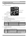
3.0 OPERATION AND DISPLAY PANEL . . . . . . . . . . . . . . . . . . . . . . . . . . . . . . . . . . . . . . . . . . .17
3.1 Control Buttons . . . . . . . . . . . . . . . . . . . . . . . . . . . . . . . . . . . . . . . . . . . . . . . . . . . . . . . . . . . . 17
3.1.1 On/Alarm Silence/Manual Battery Test button . . . . . . . . . . . . . . . . . . . . . . . . . . . . . . . . . . . . 17
3.1.2 Standby/Manual Bypass button . . . . . . . . . . . . . . . . . . . . . . . . . . . . . . . . . . . . . . . . . . . . . . . . 17
3.2 Indicators . . . . . . . . . . . . . . . . . . . . . . . . . . . . . . . . . . . . . . . . . . . . . . . . . . . . . . . . . . . . . . . . . 18
3.2.1 Level Indicators . . . . . . . . . . . . . . . . . . . . . . . . . . . . . . . . . . . . . . . . . . . . . . . . . . . . . . . . . . . . . 18
3.2.2 UPS Status Indicators . . . . . . . . . . . . . . . . . . . . . . . . . . . . . . . . . . . . . . . . . . . . . . . . . . . . . . . . 19
4.0 OPERATION . . . . . . . . . . . . . . . . . . . . . . . . . . . . . . . . . . . . . . . . . . . . . . . . . . . . . . . . . . .20
4.1 Startup Checklist for the Liebert GXT3 . . . . . . . . . . . . . . . . . . . . . . . . . . . . . . . . . . . . . . . . . 20

ii
4.2 Starting the UPS . . . . . . . . . . . . . . . . . . . . . . . . . . . . . . . . . . . . . . . . . . . . . . . . . . . . . . . . . . . 20
4.3 Manual Battery Test . . . . . . . . . . . . . . . . . . . . . . . . . . . . . . . . . . . . . . . . . . . . . . . . . . . . . . . . 20
4.4 Manual Bypass . . . . . . . . . . . . . . . . . . . . . . . . . . . . . . . . . . . . . . . . . . . . . . . . . . . . . . . . . . . . . 20
4.5 Shut Down the Liebert GXT3 . . . . . . . . . . . . . . . . . . . . . . . . . . . . . . . . . . . . . . . . . . . . . . . . . 21
4.6 Disconnecting Input Power from the Liebert GXT3. . . . . . . . . . . . . . . . . . . . . . . . . . . . . . . . 21
5.0 COMMUNICATION . . . . . . . . . . . . . . . . . . . . . . . . . . . . . . . . . . . . . . . . . . . . . . . . . . . . . . .22
5.1 Liebert IntelliSlot Communication Cards. . . . . . . . . . . . . . . . . . . . . . . . . . . . . . . . . . . . . . . . 22
5.1.1 Liebert MultiLink. . . . . . . . . . . . . . . . . . . . . . . . . . . . . . . . . . . . . . . . . . . . . . . . . . . . . . . . . . . . 22
5.2 USB Port Communication . . . . . . . . . . . . . . . . . . . . . . . . . . . . . . . . . . . . . . . . . . . . . . . . . . . . 23
5.2.1 Configuration Program . . . . . . . . . . . . . . . . . . . . . . . . . . . . . . . . . . . . . . . . . . . . . . . . . . . . . . . 23
5.3 Terminal Block Communication . . . . . . . . . . . . . . . . . . . . . . . . . . . . . . . . . . . . . . . . . . . . . . . 24
5.3.1 Any Mode Shutdown . . . . . . . . . . . . . . . . . . . . . . . . . . . . . . . . . . . . . . . . . . . . . . . . . . . . . . . . . 24
5.3.2 Battery Mode Shutdown . . . . . . . . . . . . . . . . . . . . . . . . . . . . . . . . . . . . . . . . . . . . . . . . . . . . . . 25
5.3.3 On Battery . . . . . . . . . . . . . . . . . . . . . . . . . . . . . . . . . . . . . . . . . . . . . . . . . . . . . . . . . . . . . . . . . 25
5.3.4 Low Battery . . . . . . . . . . . . . . . . . . . . . . . . . . . . . . . . . . . . . . . . . . . . . . . . . . . . . . . . . . . . . . . . 25
6.0 MAINTENANCE . . . . . . . . . . . . . . . . . . . . . . . . . . . . . . . . . . . . . . . . . . . . . . . . . . . . . . . . .26
6.1 Replacing the Internal Battery Pack. . . . . . . . . . . . . . . . . . . . . . . . . . . . . . . . . . . . . . . . . . . . 26
6.1.1 Battery Replacement Procedures . . . . . . . . . . . . . . . . . . . . . . . . . . . . . . . . . . . . . . . . . . . . . . . 26
6.2 Battery Charging . . . . . . . . . . . . . . . . . . . . . . . . . . . . . . . . . . . . . . . . . . . . . . . . . . . . . . . . . . . 27
6.3 Precautions . . . . . . . . . . . . . . . . . . . . . . . . . . . . . . . . . . . . . . . . . . . . . . . . . . . . . . . . . . . . . . . . 27
6.4 Checking UPS Status . . . . . . . . . . . . . . . . . . . . . . . . . . . . . . . . . . . . . . . . . . . . . . . . . . . . . . . . 27
6.5 Checking UPS Functions . . . . . . . . . . . . . . . . . . . . . . . . . . . . . . . . . . . . . . . . . . . . . . . . . . . . . 28
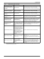
7.0 TROUBLESHOOTING . . . . . . . . . . . . . . . . . . . . . . . . . . . . . . . . . . . . . . . . . . . . . . . . . . . . .29
7.1 UPS Symptoms. . . . . . . . . . . . . . . . . . . . . . . . . . . . . . . . . . . . . . . . . . . . . . . . . . . . . . . . . . . . . 29
7.1.1 Indicators . . . . . . . . . . . . . . . . . . . . . . . . . . . . . . . . . . . . . . . . . . . . . . . . . . . . . . . . . . . . . . . . . . 29
7.1.2 Audible Alarm. . . . . . . . . . . . . . . . . . . . . . . . . . . . . . . . . . . . . . . . . . . . . . . . . . . . . . . . . . . . . . . 30
7.2 Troubleshooting . . . . . . . . . . . . . . . . . . . . . . . . . . . . . . . . . . . . . . . . . . . . . . . . . . . . . . . . . . . . 30
8.0 BATTERY CABINET . . . . . . . . . . . . . . . . . . . . . . . . . . . . . . . . . . . . . . . . . . . . . . . . . . . . . .32
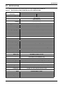
9.0 SPECIFICATIONS . . . . . . . . . . . . . . . . . . . . . . . . . . . . . . . . . . . . . . . . . . . . . . . . . . . . . . . .33
9.1 Product Warranty Registration . . . . . . . . . . . . . . . . . . . . . . . . . . . . . . . . . . . . . . . . . . . . . . . . 37

iii
FIGURES
Figure 1 Liebert GXT3-700RT230 - GXT3-3000RT230 UPS . . . . . . . . . . . . . . . . . . . . . . . . . . . . . . . . . . . . . 5
Figure 2 Rear panel components, Liebert GXT3 230V 700VA, 1000VA and 1500VA models. . . . . . . . . . . . 5
Figure 3 Rear panel components, Liebert GXT3 230V 2000VA models . . . . . . . . . . . . . . . . . . . . . . . . . . . . . 5
Figure 4 Rear panel components, Liebert GXT3 230V 3000VA models . . . . . . . . . . . . . . . . . . . . . . . . . . . . . 6
Figure 5 Operating principle diagram . . . . . . . . . . . . . . . . . . . . . . . . . . . . . . . . . . . . . . . . . . . . . . . . . . . . . . . 6
Figure 6 Support bases . . . . . . . . . . . . . . . . . . . . . . . . . . . . . . . . . . . . . . . . . . . . . . . . . . . . . . . . . . . . . . . . . . 10
Figure 7 Remove the front plastic bezel cover . . . . . . . . . . . . . . . . . . . . . . . . . . . . . . . . . . . . . . . . . . . . . . . . 10
Figure 8 Rotate the operation and display panel . . . . . . . . . . . . . . . . . . . . . . . . . . . . . . . . . . . . . . . . . . . . . . 11
Figure 9 Tower installation . . . . . . . . . . . . . . . . . . . . . . . . . . . . . . . . . . . . . . . . . . . . . . . . . . . . . . . . . . . . . . . 11
Figure 10 Pulling inner member from each bracket assembly . . . . . . . . . . . . . . . . . . . . . . . . . . . . . . . . . . . . 12
Figure 11 Installing rear member of each bracket assembly . . . . . . . . . . . . . . . . . . . . . . . . . . . . . . . . . . . . . 12
Figure 12 Installing front member of each bracket assembly . . . . . . . . . . . . . . . . . . . . . . . . . . . . . . . . . . . . . 13
Figure 13 Fastening rear member and front member together . . . . . . . . . . . . . . . . . . . . . . . . . . . . . . . . . . . 13
Figure 14 Installing inner members . . . . . . . . . . . . . . . . . . . . . . . . . . . . . . . . . . . . . . . . . . . . . . . . . . . . . . . . . 13
Figure 15 Installing rack-mount ears . . . . . . . . . . . . . . . . . . . . . . . . . . . . . . . . . . . . . . . . . . . . . . . . . . . . . . . . 14
Figure 16 Insert the UPS. . . . . . . . . . . . . . . . . . . . . . . . . . . . . . . . . . . . . . . . . . . . . . . . . . . . . . . . . . . . . . . . . . 14
Figure 17 Operation and display panel . . . . . . . . . . . . . . . . . . . . . . . . . . . . . . . . . . . . . . . . . . . . . . . . . . . . . . 17
Figure 18 Battery level indicators. . . . . . . . . . . . . . . . . . . . . . . . . . . . . . . . . . . . . . . . . . . . . . . . . . . . . . . . . . . 18
Figure 19 Load level indicators . . . . . . . . . . . . . . . . . . . . . . . . . . . . . . . . . . . . . . . . . . . . . . . . . . . . . . . . . . . . . 18
Figure 20 Terminal Block Communication pin layout. . . . . . . . . . . . . . . . . . . . . . . . . . . . . . . . . . . . . . . . . . . 24
Figure 21 Removing the front plastic bezel cover and battery door . . . . . . . . . . . . . . . . . . . . . . . . . . . . . . . . 26
Figure 22 Disconnecting the battery plug and battery connector (front view). . . . . . . . . . . . . . . . . . . . . . . . 26
Figure 23 Pulling out the battery . . . . . . . . . . . . . . . . . . . . . . . . . . . . . . . . . . . . . . . . . . . . . . . . . . . . . . . . . . . 26
Figure 24 Battery level indicator . . . . . . . . . . . . . . . . . . . . . . . . . . . . . . . . . . . . . . . . . . . . . . . . . . . . . . . . . . . 29
Figure 25 Battery cabinet . . . . . . . . . . . . . . . . . . . . . . . . . . . . . . . . . . . . . . . . . . . . . . . . . . . . . . . . . . . . . . . . . 32
TABLES
Table 1 UPS models, power ratings . . . . . . . . . . . . . . . . . . . . . . . . . . . . . . . . . . . . . . . . . . . . . . . . . . . . . . . . 4
Table 2 Specification of input circuit breaker. . . . . . . . . . . . . . . . . . . . . . . . . . . . . . . . . . . . . . . . . . . . . . . . 15
Table 3 Functions of the On/Alarm Silence/Manual Battery Test button . . . . . . . . . . . . . . . . . . . . . . . . . 17
Table 4 Functions of the Standby/Manual Bypass button . . . . . . . . . . . . . . . . . . . . . . . . . . . . . . . . . . . . . . 17
Table 5 UPS status indicators . . . . . . . . . . . . . . . . . . . . . . . . . . . . . . . . . . . . . . . . . . . . . . . . . . . . . . . . . . . . 19
Table 6 Output voltage option, all models . . . . . . . . . . . . . . . . . . . . . . . . . . . . . . . . . . . . . . . . . . . . . . . . . . 23
Table 7 Indicator descriptions . . . . . . . . . . . . . . . . . . . . . . . . . . . . . . . . . . . . . . . . . . . . . . . . . . . . . . . . . . . . 29
Table 8 Audible alarm description . . . . . . . . . . . . . . . . . . . . . . . . . . . . . . . . . . . . . . . . . . . . . . . . . . . . . . . . 30
Table 9 Troubleshooting table . . . . . . . . . . . . . . . . . . . . . . . . . . . . . . . . . . . . . . . . . . . . . . . . . . . . . . . . . . . . 30
Table 10 Specifications of GXT3-700RT230 and GXT3-1000RT230 UPS . . . . . . . . . . . . . . . . . . . . . . . . . . . 33
Table 11 Specifications of the Liebert GXT3-1500RT230, GXT3-2000RT230 and GXT3-3000RT230 . . . . 34
Table 12 Operating temperature parameters. . . . . . . . . . . . . . . . . . . . . . . . . . . . . . . . . . . . . . . . . . . . . . . . . 35
Table 13 Battery cabinet specifications . . . . . . . . . . . . . . . . . . . . . . . . . . . . . . . . . . . . . . . . . . . . . . . . . . . . . 35
Table 14 Battery run times . . . . . . . . . . . . . . . . . . . . . . . . . . . . . . . . . . . . . . . . . . . . . . . . . . . . . . . . . . . . . . . 36

iv

1
IMPORTANT SAFETY PRECAUTIONS
SAVE THESE INSTRUCTIONS
This manual contains important safety instructions that must be followed during the installation and
maintenance of the UPS and batteries. Read this manual thoroughly before attempting to install or
operate this UPS.
UPS Safety Notes
The UPS contains no user-serviceable parts except the internal battery pack. Do not remove the
cover. Removing the cover may result in electric shock and will invalidate any implied warranty.
The UPS has an internal battery, so the output receptacles of the UPS may carry live voltage even if
the UPS is not connected to mains input power.
Before moving or rewiring the UPS, disconnect mains input power and the battery and make sure
that the UPS is completely shut down. Otherwise, the output terminal may carry live voltage, pre-
senting an electric shock hazard.
To ensure human safety and normal UPS operation, the UPS must be properly grounded before use.
When the UPS is connected to an IT power distribution system, the short-circuit protection device
must be installed on the neutral line.
Install and use the UPS in the following environments:
• Temperature: 0°C to 40°C (32 - 104°F); relative humidity: 0% to 95%, non-condensing)
• Out of direct sunlight
• Away from heat source
• Stable surface, not subject to vibrations or shocks
• Away from dust and other particulates
• Away from corrosive substances, salts and flammable gases
Keep the air inlet and outlet of the UPS unobstructed. Poor ventilation will increase the UPS internal
temperature and can shorten the life of the UPS and its batteries.
Keep liquid and other foreign objects away from the UPS.
In case of fire, use a dry chemical fire extinguisher to put out the fire. Using a fluid fire extinguisher
may cause electric shock.
This UPS is not intended for use with life support and other designated critical devices. Maximum
load must not exceed that shown on the UPS rating label. This UPS is designed for data processing
equipment. If uncertain, consult your local dealer or Emerson representative.
!
WARNING
Observe all cautions and warnings in this manual. Failure to do so may result in serious
injury or death.
Refer all UPS and battery service to properly trained and qualified service personnel. Do not
attempt to service this product yourself.
Opening or removing the cover may expose you to lethal voltages within this unit even when
it is apparently not operating and the input wiring is disconnected from the electrical source.
Never work alone.

2
Battery Safety
ELECTROMAGNETIC COMPATIBILITY—The Liebert GXT3 series complies with the limits for a
Class A digital device. Operating this device in a residential area is likely to cause harmful interfer-
ence that users must correct at their own expense.
The Liebert GXT3 series complies with the requirements of EMC Directive 2004/108/EC and the pub-
lished technical standards. Continued compliance requires installation in accordance with these
instructions and use of accessories approved by Emerson.
Information for the Protection of the Environment
UPS SERVICING—This UPS makes use of components dangerous for the environment (electronic
cards, electronic components). The components removed must be taken to specialized collection and
disposal centers.
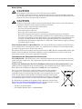
NOTICE TO EUROPEAN UNION CUSTOMERS: DISPOSAL OF OLD APPLIANCES—This
product has been supplied from an environmentally aware manufacturer that complies with the
Waste Electrical and Electronic Equipment (WEEE) Directive 2002/96/CE.
The “crossed-out wheelie bin” symbol at right is placed on this product to
encourage you to recycle wherever possible. Please be environmentally
responsible and recycle this product through your recycling facility at its end
of life. Do not dispose of this product as unsorted municipal waste. Follow
local municipal waste ordinances for proper disposal provisions to reduce the
environmental impact of waste electrical and electronic equipment (WEEE).
For information regarding the scrapping of this equipment, please browse
http://www.eu.emersonnetworkpower.com (“Products session” or “Con-
tact us” session) or call our worldwide technical support.
• Toll Free: 00 80011554499
• Toll Number Based in Italy: +39 0298250222
!
CAUTION
Do not dispose of the battery in a fire. The battery may explode.
Do not open or damage the battery. Released electrolyte is toxic and is harmful to skin and
eyes. If electrolyte comes into contact with the skin, wash the affected area immediately with
plenty of clean water and get medical attention.
!
CAUTION
A battery can present a risk of electrical shock and high short-circuit current. The following
precautions should be observed when working on batteries:
• Remove watches, rings and other metal objects.
• Use tools with insulated handles.
• Wear rubber gloves and boots.
• Do not lay tools or metal parts on top of batteries.
• Disconnect charging source prior to connecting or disconnecting battery terminals.
• Determine if the battery is inadvertently grounded. If it is inadvertently grounded, remove
the source of the ground. Contact with any part of a grounded battery can result in electri-
cal shock. The likelihood of such shock will be reduced if grounds are removed during
installation and maintenance (applicable to a UPS and a remote battery supply not having
a grounded supply circuit).

3
GLOSSARY OF SYMBOLS
Risk of electrical shock
Indicates caution followed by important instructions
AC input
AC output
Requests the user to consult the manual
Indicates the unit contains a valve-regulated lead acid battery
Recycle
DC voltage
Equipment grounding conductor
Bonded to ground
AC voltage
ON/Alarm Silence/Battery Test
OFF/Bypass
WEEE
!
i
PbH2SO4
-
+
R

Product Description
4
1.0 PRODUCT DESCRIPTION
The Liebert GXT3 is a compact, online uninterruptible power system (UPS) that continuously condi-
tions and regulates its output voltage. The Liebert GXT3 is designed to supply microcomputers and
other sensitive electronic equipment with clean sine wave input power, 700VA to 3000VA at 230V.
Upon generation, AC power is clean and stable. However, during transmission and distribution it is
subject to voltage sags, spikes and complete failure that may interrupt computer operations, cause
data loss and damage equipment.
The Liebert GXT3 protects equipment from these disturbances. The Liebert GXT3 continuously
charges its batteries from the mains, enabling it to supply power to connected loads, even when the
mains fail.
This section describes the UPS, its features, models, appearance and components, operating princi-
ples and operating mode.
1.1 Features
The UPS includes the following features:
• Intelligent battery management to extend the battery life
• Operation and display panel with LED for monitoring load percentage and battery capacity inde-
pendently
• Flexible network management with Liebert MultiLink
™
software
• Fan fault self-inspection and automated diagnostic function
• Intelligent fan operation, automatically changing rotation speed depending on system require-
ments, to decrease power consumption and noise
• Input circuit breaker to ease recovery from overloads
• CE mark and safety approval from CE
• Communication options: USB port, Liebert IntelliSlot
®
port and terminal block communication
• Dry contacts for remote monitoring
• Input power factor greater than 0.99
• Output voltage selection function
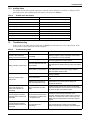
1.2 Available Models
Available models of the UPS are shown in Table 1:
Table 1 UPS models, power ratings
Model Nominal Power Rating
GXT3-700RT230 700VA/630W
GXT3-1000RT230 1000VA/900W
GXT3-1500RT230 1500VA/1350W
GXT3-2000RT230 2000VA/1800W
GXT3-3000RT230 3000VA/2700W

Product Description
5
1.3 Appearance and Components
1.3.1 Appearance
The Liebert GXT3 rack/tower models in various power ratings have the same general appearance,
controls and features (see Figure 1). The various rack/tower models differ largely in the type of
receptacles each has.
Figure 1 Liebert GXT3-700RT230 - GXT3-3000RT230 UPS
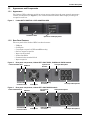
1.3.2 Rear Panel Features
The rear panel of the Liebert GXT3 has these features:
•USB port
• Cooling fan
• C19 output receptacle (GXT3-3000RT230 only)
• Six C13 output receptacles
• Input circuit breaker
• Liebert IntelliSlot
• Communication terminal block
• Input receptacle
Figure 2 Rear panel components, Liebert GXT3 230V 700VA, 1000VA and 1500VA models
Figure 3 Rear panel components, Liebert GXT3 230V 2000VA models
Operation and Display Panel
Ventilation Slots
C14 Input Receptacle
External Battery
Connector
Cooling Fan
Input Circuit
Breaker
C13 Output Receptacles
Liebert IntelliSlot Port
USB Port
Terminal Block
Communication
C20 Input Receptacle
External Battery
Connector
Cooling Fan
C13 Output Receptacles
Liebert IntelliSlot
Port
USB Port
Terminal Block
Communication
Input Circuit
Breaker

Product Description
6
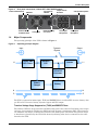
Figure 4 Rear panel components, Liebert GXT3 230V 3000VA models
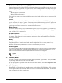
1.4 Major Components
The operating principle of the UPS is shown in Figure 5.
Figure 5 Operating principle diagram
The UPS is composed of mains input, TVSS and EMI/RFI filters, rectifier/PFC, inverter, battery char-
ger, DC-to-DC converter, battery, dynamic bypass and UPS output.
Transient Voltage Surge Suppression (TVSS) and EMI/RFI Filters
The Liebert GXT3 has surge protection and filters that protect the connected load from power surges
and sags, electromagnetic interference (EMI) and radio frequency interference (RFI). These features
can minimize any surges or interference present in the mains power. The filters also prevent surges
or interference generated by the UPS from adversely affecting other devices connected on the same
branch as the UPS.
C20 Input Receptacle
Output Circuit
Breakers
Cooling Fan
C13 Output
Receptacles
Liebert IntelliSlot
Port
USB Port
Terminal Block
Communication
C19 Output
Receptacle
Input Circuit
Breaker
External Battery
Connector
L1
Dynamic
Bypass
Input
DC-to-DC
Converter
Rectifier /
PFC
Inverter
Battery
Battery
Charger
L1
TVSS & EMI/
RFI Filters
N
Output
N
G
G

Product Description
7
Rectifier/Power Factor Correction (PFC) Circuit
In normal operation, the Liebert GXT3’s rectifier/power factor correction (PFC) circuit converts mains
power to regulated DC power for use by the inverter while ensuring that the wave shape of the input
current used by the UPS is near ideal. Extracting this sine wave input current achieves two objec-
tives:
• Efficient power use by the UPS
• Reduced reflected harmonics
This results in cleaner power being available to other devices in the building that are not protected by
the UPS.
Inverter
In normal operation, the Liebert GXT3’s inverter utilizes the DC output of the PFC circuit to produce
precise, regulated sine wave AC power. When mains power fails, the inverter receives DC power from
the battery through the DC-to DC converter. In either operation mode, the UPS inverter is online,
continuously generating clean, precise, regulated AC output power.
Battery Charger
The battery charger utilizes energy from the mains power and precisely regulates it to continuously
float charge the batteries. The batteries are being charged whenever the Liebert GXT3 is plugged in,
even when the UPS is not turned on.
DC-to-DC Converter
The DC-to-DC converter raises the DC voltage from the battery to the optimum operating voltage for
the inverter. This allows the inverter to operate continuously at its optimum efficiency and voltage,
increasing reliability.
Battery
The Liebert GXT3 utilizes valve-regulated, nonspillable, lead acid batteries. To maintain battery
design life, operate the Liebert GXT3 in an ambient temperature of 0°C to 25°C (32°F to 77°F).
Optional external battery cabinets are available to extend battery run times.
Dynamic Bypass
The Liebert GXT3 provides an alternate path for mains power to the connected loads in the unlikely
event of a UPS malfunction. Should the Liebert GXT3 have an overload, overtemperature, or UPS
failure condition, the UPS automatically transfers the connected loads to bypass.
1.5 Operating Mode
The UPS operation modes include the following: Mains (AC) Mode, Bypass Mode, Battery Mode, Bat-
tery Recharge Mode and Frequency Converter Mode.
For the descriptions of operation mode indicators and control buttons, refer to 3.0 - Operation and
Display Panel.
1.5.1 Mains (AC) Mode
During Mains (AC) Mode, the mains provides energy to the Liebert GXT3. The filters, PFC circuit and
inverter process this power to provide high-level power to connected loads. Meanwhile, the UPS main-
tains the batteries in a fully charged state.
NOTE
The bypass power path does not protect the connected loads from disturbances on the mains.

Product Description
8
1.5.2 Manual Bypass Mode
Manual Bypass Mode occurs when the Standby/Manual Bypass button is pressed and held for about
2 seconds while the Liebert GXT3 is in Mains (AC) Mode. Bypass operation is indicated by an audible
alarm and illuminated amber bypass indicator. (If other indicators are illuminated, refer to 7.0 -
Troubleshooting). During Bypass Mode, mains power bypasses the inverter and provides energy to
the connected load.
NOTICE
Turning off the UPS in Bypass Mode will result in loss of output power.
1.5.3 Battery Mode
The Liebert GXT3 enters Battery Mode when mains power fails or is outside acceptable values. The
battery system supplies power through the DC-to-DC converter to the inverter to generate clean AC
power for the connected loads.
When the Liebert GXT3 enters Battery Mode, the UPS sounds a half-second beep at 10-second inter-
vals. When approximately 2 minutes of run time remains, the beeps sound every 5 seconds to warn
that the battery is getting low (this Low Battery Warning is user-configurable).
In Battery Mode, the AC Input indicator is Off and the Battery Level indicators illuminate to warn
that a mains problem has occurred. Each battery level indicator represents a 20% capacity level. As
capacity decreases, fewer indicators remain illuminated. Refer to 7.0 - Troubleshooting.
For approximate battery run times, refer to 9.0 - Specifications. The times in Table 14 are approxi-
mate. They are based on resistive load and an ambient temperature of 25°C (77°F). To increase this
time, turn off non-essential loads (such as idle computers and monitors) or add optional external bat-
tery cabinets.
NOTICE
Turning Off the Liebert GXT3 when it is in Battery Mode will result in loss of output power.
If the UPS is turned Off manually, it must be manually restarted after mains power returns.
If the UPS is turned Off by a communication signal or because the batteries are depleted, it
will operate as selected in the configuration program for Auto-Restart (Refer to 5.2.1 -
Configuration Program).
1.5.4 Battery Recharge Mode
Once mains power is applied to the Liebert GXT3, the Battery Charger begins charging the batteries.
1.5.5 Frequency Converter Mode
All models of the Liebert GXT3 are capable of frequency conversion. Frequency Conversion Mode can
be selected using the configuration program. Allowable frequency operating modes include:
• Auto Sensing - 50Hz or 60 Hz – Bypass Enabled
• Auto Sensing - 50Hz or 60 Hz – Bypass Disabled
• Frequency Converter - 50Hz – Bypass Disabled
• Frequency Converter - 60Hz – Bypass Disabled
NOTE
The default for all models of the Liebert GXT3 is “Auto Sensing - 50Hz or 60 Hz – Bypass
Enabled.”
!
CAUTION
Do not touch the AC input receptacle when the UPS is operating. AC input voltages may still
be present even when the AC input indicator is Off.

Installation
9
2.0 INSTALLATION
2.1 Unpacking and Inspection
Unpack the UPS and conduct the following checks:
• Inspect the UPS for shipping damage. If any shipping damage is found, report it to the carrier and
your local dealer or Emerson representative immediately.
• Check the accessories against the delivery list. If there is any discrepancy, contact your local
dealer or your Emerson representative immediately.
2.2 What’s Included
With GXT3 UPS
• Terminal Block Communication terminals
• Compact Disk with:
• Liebert MultiLink
• Configuration Program
• User Manual
• USB Cable: one, 2m (6-1/2 ft.) long
• Mounting hardware, including screws and handles
• Plastic tower stand sets: 2 (four pieces)
• Warnings, Safety Instructions booklet and WEEE recycling sheet (ISO 14001 compliance)
• for 700VA - 1500VA: (2) 10A IEC C13 C14 Output Cable, 2m (6-1/2 ft.) long
• for 2000VA - 3000VA:
• (3) 10A IEC C13 C14 Output Cable, 2m (6-1/2 ft.) long
• (1) CEE 7/7 (Schuko) to IEC C20 Input Cable, 2.5m (8-1/5 ft.) long
• (1) BS1363 (UK) to IEC C20 Input Cable, 2.5m (8-1/5 ft.) long
2.3 Preparation for Installation
2.3.1 Installation Environment
• Install the UPS indoors in a controlled environment, where it cannot be accidentally turned Off.
The installation environment should meet the specifications in 9.0 - Specifications.
• Place the UPS in an area where airflow around the unit is unrestricted and away from water,
flammable liquids, gases, corrosives and conductive contaminants. Avoid direct sunlight.
Installation Clearances
Maintain a clearance of at least 100mm (4 inches) in the front and rear of the Liebert GXT3. Do not
obstruct the air inlets on the front panel and rear panel of the UPS; blocking the air inlets reduces
ventilation and heat dissipation, shortening the service life of the Liebert GXT3.
NOTE
The GXT3 External Battery Cabinet shipping package includes one battery cabinet, two
spacers for tower configuration and one DC power cable.
NOTE
Operating the Liebert GXT3 in temperatures above 25°C (77°F) reduces battery life.

Installation
10
2.4 Mechanical Installation
The Liebert GXT3 may be installed as a tower or in a rack, depending on space and use consider-
ations. The Liebert GXT3 may be used alone, as a single UPS, or with up to four battery cabinets.
2.4.1 Tower Installation
To install the Liebert GXT3 as a tower:
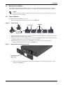
1. Take out support bases from the accessories (see Figure 6).
Figure 6 Support bases
2. If optional Liebert external battery cabinets will be connected to the Liebert GXT3, take out the
spacers delivered with the battery cabinet.
3. Connect the spacers and the support bases as shown in Figure 6. Each Liebert GXT3 needs two
assembled support bases, one in the front and one in the rear.
4. Adjust the direction of the operation and display panel and logo on the Liebert GXT3.
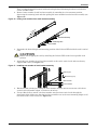
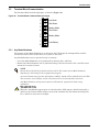
a. Remove the front plastic bezel cover (see Figure 7).
Figure 7 Remove the front plastic bezel cover
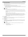
b. Pull the operation and display panel, rotate it 90 degrees clockwise and snap it back into
position (see Figure 8).
NOTE
When installing the UPS or making input and output connections, comply with all relevant
safety codes and standards.
Support Bases
Spacers
Connectors
Front Plastic
Bezel Cover

Installation
11
Figure 8 Rotate the operation and display panel
c. Pull the logo on the front plastic bezel cover, rotate it 90 degrees clockwise and snap it back
into position. The rotated front plastic bezel cover is shown in Figure 9.
d. Replace the front plastic bezel cover on the Liebert GXT3. At this point, the UPS operation
and display panel and logo have been rotated 90 degrees clockwise, which provides upright
viewing for users.
5. Place the Liebert GXT3 and any battery cabinets on the support bases. Each Liebert GXT3 needs
four support bases, as shown in Figure 9.
Figure 9 Tower installation
2.4.2 Rack Installation
To install a Liebert GXT3 UPS in a rack:
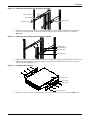
1. Unpack the two bracket assemblies and mounting hardware from the rack-mounting kit
(P/N: RMKIT18-32). Bracket assembly includes inner member, front member and rear member.
NOTE
• When the Liebert GXT3 is installed in a rack, the UPS must be supported by a shelf,
brackets, or slide rails on each side. The factory-supplied rack-mount ears cannot support
the weight of the UPS. They are used to move the UPS into and out of the rack and attach the
UPS to the rack.
• Mounting hardware and slide rails are sold separately. Contact your local dealer or
Emerson representative for these options and any assistance.
Operation and Display Panel
Rotated Clockwise 90 Degrees
Operation and
Display Panel
Rotated for
Tower Operation
Support Bases
Support Bases
Liebert GXT3 UPS
Liebert GXT3 UPS and
External Battery Cabinet

Installation
12
They are interchangeable between left-hand and right-hand. Mounting hardware includes M4
screws and M5 screws.
2. Remove inner member of each bracket assembly by extending it to its outermost position,
depressing the retaining latch and then pulling the inner member from the bracket assembly (see
Figure 10).
Figure 10 Pulling inner member from each bracket assembly
3. Determine the desired height and mounting position of the Liebert GXT3 inside the rack’s vertical
rails.
4. Attach the rear member of each bracket assembly to the rack’s vertical rails with two factory-
supplied M5 screws (see Figure 11).
Figure 11 Installing rear member of each bracket assembly
5. Extend bracket assembly by sliding the front member forward until it touches the rack’s front
vertical rails (adjustable length: 18 inches to 32 inches).
6. Use two M5 screws to attach each front member onto the front vertical rails through the
installation holes. Make sure that the bracket assemblies are at the same mounting height on all
four of the rack’s vertical rails (see Figure 12.)
!
CAUTION
Reduce risk of tipping the rack by installing the Liebert GXT3 in the lowest possible rack
position.
Inner member
Bracket assembly
P
u
l
l
o
u
t
Retaining latch
M5 screw (4 pcs)
Vertical pole
Rear member
Front member

Installation
13
Figure 12 Installing front member of each bracket assembly
7. Fasten the rear and front members together using four M4 screws and four M4 nuts (M4 nuts
have been installed on the rear member before delivery) per bracket assembly, as shown in
Figure 13.
Figure 13 Fastening rear member and front member together
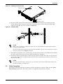
8. Fasten inner members pulled from the bracket assemblies in Step 2 to the UPS on both sides with
eight M4 screws provided in this kit. Make sure that the retaining latch is near the rear of the
UPS, as shown in Figure 14.
Figure 14 Installing inner members
9. Use M4 screws to install ears of accessories on both sides of the UPS, as shown in Figure 15.
Front vertical pole
M5 screw (4 pcs)
Front member
Rear member
S
l
i
d
e
M4 screw (8 pcs)
Rear member
Front member
M4 nut (8 pcs)
M4 screw
, 8 pieces
Retaining Latch
Liebert GXT3 UPS
Inner Member

Installation
14
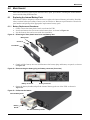
Figure 15 Installing rack-mount ears
10. Insert the UPS, with inner members attached, into bracket assemblies by inserting top and
bottom edges of inner members into the top and bottom curved tracks of front members and
sliding the UPS into the rack, as shown in Figure 16.
Figure 16 Insert the UPS
11. Through the rack-mount ears, use M5 screws provided in this kit to secure the front of the UPS to
the rack’s vertical rails to prevent the UPS from sliding out of position.
12. If optional Liebert external battery cabinets will be connected to the UPS, they can be placed all
on one side of the UPS or stacked beneath the UPS. The installation procedures are the same as
those for the UPS.
2.5 Cable Connection
The Liebert GXT3 rear panel has an input receptacle and output receptacles. Refer to 1.3.2 - Rear
Panel Features for details. The battery cables are supplied with the battery cabinet.
NOTE
Ends of inner members are tapered to allow the rear of the UPS to be angled upward before
insertion, if space allows.
The UPS should move smoothly into the bracket assemblies. If not, recheck alignment of front
and rear members from Steps 4 through 7.
NOTE
Up to four external battery cabinets can be connected to the Liebert GXT3. Each cabinet will
increase the battery recharge time.
M4 Screw
, 8 pieces
Ear,
2pieces
Liebert GXT3 UPS
Inner Member
Front Member
Insert
Page is loading ...
Page is loading ...
Page is loading ...
Page is loading ...
Page is loading ...
Page is loading ...
Page is loading ...
Page is loading ...
Page is loading ...
Page is loading ...
Page is loading ...
Page is loading ...
Page is loading ...
Page is loading ...
Page is loading ...
Page is loading ...
Page is loading ...
Page is loading ...
Page is loading ...
Page is loading ...
Page is loading ...
Page is loading ...
Page is loading ...
Page is loading ...
-
 1
1
-
 2
2
-
 3
3
-
 4
4
-
 5
5
-
 6
6
-
 7
7
-
 8
8
-
 9
9
-
 10
10
-
 11
11
-
 12
12
-
 13
13
-
 14
14
-
 15
15
-
 16
16
-
 17
17
-
 18
18
-
 19
19
-
 20
20
-
 21
21
-
 22
22
-
 23
23
-
 24
24
-
 25
25
-
 26
26
-
 27
27
-
 28
28
-
 29
29
-
 30
30
-
 31
31
-
 32
32
-
 33
33
-
 34
34
-
 35
35
-
 36
36
-
 37
37
-
 38
38
-
 39
39
-
 40
40
-
 41
41
-
 42
42
-
 43
43
-
 44
44


Emerson Liebert GXT3 1000VA User manual
- Type
- User manual
- This manual is also suitable for
Ask a question and I''ll find the answer in the document
Finding information in a document is now easier with AI
Related papers
Other documents
-
Avocent GXT3-3000RT120 Datasheet
-
Liebert GXT3 User manual
-
-
-
Approx APPUPS700V2 Datasheet
-
-
-
-
-