
For more information, visit www.desatech.com
WARNING: If the information in this manual is not fol-
— WHAT TO DO IF YOU SMELL GAS
• Do not touch any electrical switch; do not use any
-
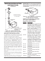
DIRECT-VENT CORNER UNIT FIREPLACE
OWNER’S OPERATION AND INSTALLATION MANUAL
NATURAL GAS MODELS
(V)DVF36TCR(E) AND (V)DVF36TCL(E)
(V)DVF36TCR(-HA) AND (V)DVF36TCL(-HA)
PROPANE/LP GAS MODELS
(V)DVF36TCRP(E) AND (V)DVF36TCLP(E)
Model Shown

www.desatech.com
112108-01C2
TAbLE OF CONTENTS
Safety Information ............................................... 2
Dimensions .......................................................... 5
Pre-Installation Preparation ................................. 5
General Venting ................................................... 8
Venting Installation Instructions ......................... 10
Installation ......................................................... 18
Pilot/Electrode Assembly Adjustment ................ 23
Burner Flame Adjustment .................................. 24
Cleaning and Maintenance ................................ 25
Operating Fireplace ........................................... 26
Specications .................................................... 28
Service Hints ..................................................... 28
Technical Service............................................... 28
Replacement Parts ............................................ 28
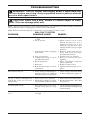
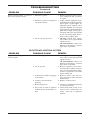
Troubleshooting ................................................. 29
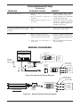
Wiring Diagrams ................................................ 31
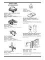
Parts and Accessories ....................................... 32
Warranty Information ...........................Back Cover
SAFETy INFORMATION
-
-
teration, service or main-
to this manual for correct
-
-
tance or additional infor-
-
stalled in an aftermarket,*
-
This Direct-Vent Gas Fire-
intended for use with
State of Massachusetts:
The installation must
the Commonwealth of
-
known to the State of California
-

www.desatech.com
112108-01C 3
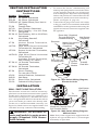
Modles (V)DVF36TCRE, (V)DVF36TCRPE,
(V)DVF36TCLE and (V)DVF36TCLPE use a
direct spark ignition with a 24 VAC control mod-
ule. All models have HI/LO valve that controls
the ame height.
Fan Kit models DVFFBK and DVFFBKT are
available for these units as an option. If you are
uncertain as to what gas your unit is equipped for,
please check the rating plate located in the interior
of the appliance opening or consult your local
distributor of DESA products.
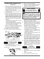
Early signs of
carbon monoxide poisoning resemble the u, with
headaches, dizziness or nausea. If you have these
signs, the replace may not be working properly.
Get fresh air at once! Have replace serviced.
Some people are more affected by carbon monoxide
than others. These include pregnant women, people
with heart or lung disease or anemia, those under the
inuence of alcohol and those at high altitudes.
Natural and propane/
LP gas are odorless. An odor-making agent is added
to the gas. The odor helps you detect a gas leak.
However, the odor added to the gas can fade. Gas
may be present even though no odor exists.
Make certain you read and understand all warnings.
Keep this manual for reference. It is your guide to
safe and proper operation of this replace.
-
-
Before beginning the installation of the replace,
read these instructions through completely.
• This DESA replace and its components are
safe when installed according to this installation
manual. Unless you use DESA components,
which have been designed and tested for the
replace system, you may cause a re hazard.
• The DESA warranty will be voided by and
DESA disclaims any responsibility for the fol-
lowing actions:
a) Modication of the replace, components,
doors, air inlet system and damper control.
b) Use of any component part not manufactured
or approved by DESA in combination with
a DESA replace system.
c) Installation and/or operation in a manner
other than instructed in this manual.
d) Burning of anything other than the type of
gas approved for use in this gas appliance.
This appliance, when installed, must be electrically
grounded in accordance with local codes, or in the
absence of local codes, with the National Electri-
cal Code, ANSI/NFPA 70 or CSA C22.1 Canadian
Electrical Code for Canada.
The installation must conform to local codes,
or in the absence of local codes, with the Na-
tional Fuel Gas Code ANSI Z223.1 (CAN B149.
in CANADA)
This appliance complies with ANSI Z21.50, and
CSA 2.22-2000 as a VENTED GAS FIREPLACE
and is listed and tested by the Canadian Standards
Association.
Proper installation is the most important step in
ensuring safe and continuous operation of the
replace. Consult the local building codes as to
the particular requirements concerned with the
installation of all factory built replaces.
This replace must be installed by a qualied (cer-
tied or licensed) service person. It has a sealed
gas combustion chamber that uses a millivolt gas
control valve with a millivolt ignition system.
Models (V)DVF36TCR, (V)DVF36TCRP,
(V)DVF36TCL and (V)DVF36TCLP are direct-
vent replaces with sealed combustion chambers
that use a millivolt gas control valve with a mil-
livolt ignition system.
SAFETy INFORMATION
Continued

www.desatech.com
112108-01C4
WARNING: Do not allow fans
-
-
adults away from hot surface to
-
-
dren when they are in the room
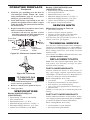
1. For propane/LP replace, do not place pro-
pane/LP supply tank(s) inside any structure.
Locate propane/LP supply tank(s) outdoors.
To prevent performance problems, do not
use propane/LP fuel tank of less than 100 lbs.
capacity.
SAFETy INFORMATION
Continued
2. If you smell gas
• shut off gas supply
• do not try to light any appliance
• do not touch any electrical switch; do not use
any phone in your building
• immediately call your gas supplier from a
neighbor’s phone. Follow the gas supplier's
instructions
• if you cannot reach you gas supplier, call the
re department.
3. Never install the replace
• in a recreational vehicle
• in windy or drafty areas where curtains or
other combustible (ammable) objects can
make contact with the replace front
• in high trafc areas
4. Turn replace off and let cool before servicing,
installing or repairing. Only a qualied service
person should install, service or repair this
replace. Have replace inspected annually
by a qualied service person.
5. You must keep control compartments, burn-
ers and circulating air passages clean. More
frequent cleaning may be needed due to ex-
cessive lint and dust from carpeting, bedding
material, etc. Turn off the gas valve and pilot
light before cleaning replace.
6. Have venting system inspected annually by a
qualied service person. If needed, have vent-
ing system cleaned or repaired. See Operating
Guidelines and Maintenance Instructions,
page 25.
7. Do not use any solid fuels (wood, coal, paper,
cardboard, etc.) in this replace. Use only the
gas type indicated on replace nameplate.
8. Do not use replace if any part has been ex-
posed to or under water. Immediately call a
qualied service person to arrange for replace-
ment of the unit.
9. Do not operate replace if any log is broken.
10. Do not operate fireplace with glass door
removed, cracked or broken.
11. Provide adequate clearances around air
openings.
12. Fireplaces with the sufx of -HA have been
designed to operate at altitudes of 4000 feet
and above. For horizontal installations above
2,000 feet, it is recommened that a 12" exten-
sion pipe be added before starter elbow (see
High Altitude Installation, page 17).

www.desatech.com
112108-01C 5
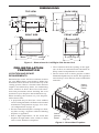
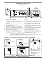
DIMENSIONS
FRONT VIEW
30"
(Opening)
25"
19
7
/
8
"
(Opening)
RIGHT SIDE
1
7
/
8
"
22
5
/
8
"
41
1
/
8
"
32"(Opening)
1
7
/
8
"
39
3
/
4
"
26
3
/
8
"
3"
1"
3
1
/
2
"
22
5
/
8
"
34
3
/
4
"
3"
BACK VIEWTOP VIEW
(Left Side)
(Right Side)
(Front)
(Back)
24"
10
1
/
2
"
1
1
/
2
"ø 1
1
/
2
"ø
10
1
/
2
"
11
15
/
16
"
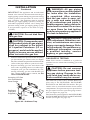
PRE-INSTALLATION
PREPARATION
REQUIREMENTS
Determine the safest and most efcient location
for your DESA direct-vent replace. Make sure
that rafters and wall studs are not in the way of the
venting system. Choose a location where the heat
output is not affected by drafts, air conditioning
ducts, windows or doors. Be aware of all restric-
tions and precautions before deciding the exact
location for your replace and termination cap.
When deciding the location of your replace,
follow these rules:
• A projection may be ideal for a new addition
on an existing nished wall. Refer to horizontal
termination congurations on page 13 or verti-
cal congurations on page 15.
• Do not connect this replace venting to a chim-
ney ue serving a separate solid-fuel burning
replace or appliance.
• Due to high temperatures, do not locate this
replace in high trafc areas, windy or drafty
areas or near furniture or draperies.
• Never obstruct the front opening of the appli-
ance or ow of combustion and ventilation air.
Keep control compartments accessible.
• Do not locate close to where gasoline or other
ammable liquids may be stored. The appliance
must be kept clear and free from combustible
materials.
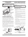
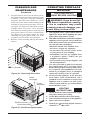
Figure 1 - Dimensions for Left/Right Side Corner Unit
Figure 2 - Direct-Vent Fireplace
Log Set
Upper
Louver
Panel
Lower
Louver
Panel

www.desatech.com
112108-01C6
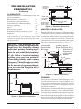
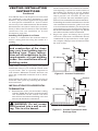
CLEARANCES
Minimum clearances to combustibles for the re-
place are as follows:
Back and Sides of Surround* 0"
Vent Surface (Side and Bottom) 1"
Top Vent Surface (Horizontal Run) 2"
Ceiling to Opening 36"
Floor 0"
Wall to Front of Glass 36"
Perpendicular Wall to Opening of Unit 2"
Top Spacer 0"
* For back and sides of replace, do not pack
with insulation or other materials. Zero inch
clearance to combustible materials are for fram-
ing purpose only.
-
-
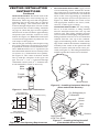
MANTEL CLEARANCES
Woodwork, such as wood trims, mantels and other
combustible materials should not be placed within
7" of the opening of this replace (see Figure 5).
Combustible material above projecting more than
1
1
/
2
" from the appliance’s front face must not be
placed less than 15" from the opening of the appli-
ance (ref. NFPA Standard 211 Sec. 7-3.3.3).
PRE-INSTALLATION
PREPARATION
Continued
0"
36"
2"
Wall In Front Of Glass
36" Min.
Perpendicular
Wall 2" Min.
From Opening
Right Side
Surround
(0" Min.)
Left Side
Surround
(0" Min.)
TOP VIEW
Figure 3 - Minimum Clearances
Figure 4 - Minimum Clearances
CEILING
WALL
36" Min.
36" Min.
0" Floor
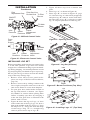
FRAMING
Once the nal location has been determined, ob-
serving clearances for the vent termination, you
may construct framing using dimensions shown
in Figures 6 to 10 on page 7 depending on your
particular installation
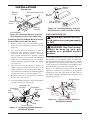
If the appliance is to be installed directly on carpeting,
tile (other than ceramic), or any combustible mate-
rial other than wood ooring, the appliance must be
installed upon a metal or wood panel extending the
full width and depth of the appliance. There are three
holes on each side of the bottom of the unit where
screws can be used to secure the unit to the oor.
Figure 5 - Mantel Clearances
21" Min.
15" Min.
12" Min.
4"
Min.
7" Min.
1
1
/
2
" Max.
UNIT
Spacer
2 x 4
Combustible
Material May
Be Used
Drywall (Gypsum
Board, Sheetrock, Etc.)
Safe Zone for
Projection of
Combustible
Material

www.desatech.com
112108-01C 7
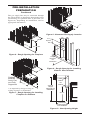
PRE-INSTALLATION
PREPARATION
Continued
Figure 6 - Rough Opening for Fireplace
39
3
/
4
" Min.
40
1
/
2
"
24"
39
3
/
4
"
Min.
40
1
/
2
"
24"
*
Figure 7 - Rough Opening for Installing
Fireplace on Platform
* As required by design as long as
ceiling clearance is maintained.
Platform
Must Be
Solid, Flat,
and Fully
Supported
Figure 8 - Alternate Gas Supply Location
11
15
/
16
"
10
1
/
2
"
20
3
/
16
"
1
1
/
2
"
The gas supply line may be connected through
the side framing or alternately through the lower
sub-ooring or a platform base if provided (see
Figures 8). Depending on installation, refer to
appropriate illustrations.
Height
Depends
On
Installation
10
3
/
4
"
Square
Min.
Figure 9 - Rough Opening for Installing
Exterior Vent Terminal
Vertical
Height
Depends on
Installation
26
3
/
8
"
Horizontal
Length Depends
on Installation
90
o
Elbow
45
o
Elbow
Figure 10 - Vent Opening Height

www.desatech.com
112108-01C8
GENERAL VENTING
These models are approved for use with DESA 58
Series, rigid type direct vent pipe as supplied by
DESA or with approved types of exible vent pipe
(not supplied) when appropriately sized for an 8"
outer and 5" inner diameter application.
Your replace is approved to be vented either hori-
zontally through a side wall, or vertically through
a rooine using the following guidelines:
• Only use DESA supplied or approved types
of venting components or kits. Do not mix
different types of vent components, modify
vent components or custom fabricate vent
components for use in any one installation.
• Minimum clearance between vent pipes and
combustible materials is 1", except where stated
otherwise.
• Combustible material may be ush with the top
front of replace with a maximum thickness
of 3/4".
• Do not recess venting terminals into a wall
or siding.
• Do not install vent terminals below grade level.
Maintain a minimum height of 12" above snow
line.
• Do not terminate venting system into an attic
or garage.
• If using a venting conguration of only hori-
zontal venting with no vertical run, a 1/4" rise
for every 12" of run toward the termination is
required.
• There must not be any obstruction such as
bushes, garden sheds, fences, decks, or util-
ity buildings within 24" from the front of the
termination cap.
• Do not locate termination cap where excessive
snow or ice build up may occur. Be sure to clear
vent termination area after snow falls to prevent
accidental blockage of venting system. When
using snow blowers, do not direct snow towards
vent termination area.
VENT TERMINATION CLEARANCES
The nal position of your appliance depends on
the location of the vent termination in relation to
the clearances that must be observed as shown in
Figure 11, page 9.
You may avoid extra framing by positioning your
replace against an already existing framing mem-
ber. The back of the replace may be positioned
directly against a combustible wall.
*Check with local codes or with the CANCGA
B149.1 or B149.2 Installation Codes for Canada
installations. In the USA, follow the current Na-
tional Fuel Gas Fuel Gas Code, ANS Z223.1 also
known as NFPA 54.

www.desatech.com
112108-01C 9
Fixed
Closed
Openable
Fixed
Closed
V
V
V
V
V
V
V
V
X
X
V
X
G
G
J
F
B
B
K
N
H
I
A
N
E
L
D
B
M
A
C
B
V
V
A
G
G
B
TERMINATION CAP
AIR SUPPLY INLET
GAS METER RESTRICTED AREA
(TERMINATION PROHIBITED)
A = clearance above grade, veranda, porch, deck, or
balcony [*12" (30.5 cm) minimum]
B = clearance to window or door that may be opened
[6" (15 cm) min. for 10,000 Btu or less; 9" (23 cm) in US
if between 10,000 and 50,000, 12" (30 cm) in Canada
if between 10,000 and 100,000; 12" (30 cm) in US if
greater than 50,000, 36" (91 cm) in Canada if greater
than 100,000]
C = clearance to permanently closed window
[minimum 12" (30.5 cm) recommended to prevent
condensation on window]
D = vertical clearance to ventilated soffit located above the
terminal within a horizontal distance of 24" (61 cm) from
the center-line of the terminal [18" (45.7 cm) minimum]
E = clearance to unventilated soffit [12" (30.5 cm) minimum]
F = clearance to outside corner (see below)
G = clearance to inside corner (see below)
H = *not to be installed above a meter/regulator assembly
within 36" (91.4 cm) horizontally from the center line
of the regulator
I = clearance to service regulator vent outlet [*72" (182.9 cm)
minimum]
J = clearance to non-mechanical air supply inlet to building
or the combustion air inlet to any other fireplace
[6" (15 cm) min. for 10,000 Btu or less; 9" (23 cm) in US
if between 10,000 and 50,000, 12" (30 cm) in Canada
if between 10,000 and 100,000; 12" (30 cm) in US if
greater than 50,000, 36" (91 cm) in Canada if greater
than 100,000]
K = clearance to a mechanical air supply inlet [*In Canada,
6 ft. (1.83m) minimum; In US 3 ft. (91 cm) above if within
10 ft. (3 m) horizontally]
L = † clearance above paved side-walk or a paved driveway
located on public property [*84" (213.3 cm) minimum]
M = clearance under veranda, porch, deck
[*12" (30.5 cm) minimum ‡]
N = clearance above a roof shall extend a minimum of
24" (61 cm) above the highest point when it passes
through the roof surface and any other obstruction within
a horizontal distance of 18" (45.7 cm)
† vent shall not terminate directly above a side-walk or paved driveway which is located between two
single family dwellings and serves both dwellings*
‡ only permitted if veranda, porch, deck or balconey is fully open on a minimum of 2 sides beneath the floor*
* as specified in CAN/CSA B149 (.1 or .2) Installation Codes (1991) for Canada and U.S.A.
Note: Local codes or regulations may require different clearances
A = 6" (15.2 cm)
Inside Corner
V
B
E
V
B = 6" (15.2 cm)
C = Maximum depth of 48" (121.9 cm)
for recessed location
D = Minimum width for back wall of
recessed location -
Combustible - 38" (965 mm)
Noncombustible - 24" (61 cm)
E = Clearance from corner in
recessed location-
Combustible - 6" (15.2 cm)
Noncombustible - 2" (5.1 cm)
Outside Corner Recessed Location
G
H
G = 12" (30.5 cm) minimum clearance
Balcony with No Side Wall
V
J
Combustible &
Noncombustible
H = 24" (61 cm)
J = 20" (50.8 cm)
Balcony with Perpendicular Side Wall
C
D
C
Termination Clearances for Buildings with Combustible and Noncombustible Exteriors
Openable
Figure 11 - Minimum Clearances for Termination Cap
GENERAL VENTING
Continued

www.desatech.com
112108-01C10
VENTING INSTALLATION
INSTRUCTIONS
WARNING: Read all instruc-
Failure to do so could result in
WARNING: Seal all connec-
silicone every time a vent con-
sealant to the male end of the
-
seal any connections after main-
NOTICE: Failure to follow these in-
NOTICE: Do not seal termination
INSTALLATION
Consult local building codes before beginning the
installation. The installer must make sure to select
the proper vent system for installation. Before
installing vent kit, the installer must read this
replace manual and vent kit instructions.
Only a qualied service person should install
venting system. The installer must follow these
safety rules:
• Wear gloves and safety glasses for protection
• Use extreme caution when using ladders or
when on roof tops
• Be aware of electrical wiring locations in walls
and ceilings
The following actions will void the warranty on
your venting system:
• Installation of any damaged venting component
• Unauthorized modication of the venting sys-
tem (Do not cut or alter vent components)
• Installation of any component part not manu-
factured or approved by DESA
• Installation other than as instructed by these
instructions
There are two basic types of direct-vent installation:
• Horizontal Termination
• Vertical Termination
It is important to select the proper length of vent
pipe for the type of termination you choose. It is
also important to note the wall thickness.
For Horizontal Termination: Select the amount of
vertical rise desired. The horizontal run of venting
must have 1/4" rise for every 12" of run towards
the termination.
WARNING: Never run the
vent downward as this may
You may use one or two 90° elbows in this vent
conguration. See Horizontal Termination Con-
gurations on page 13.
For Vertical Termination: Measure the distance
from the replace ue outlet to the ceiling. Add
the ceiling thickness, the vertical rise in an attic or
second story, and allow for sufcient vent height
above the roof line. You may use one or two 90°
elbows in this vent conguration. See Vertical
Termination Congurations on page 16.
Note: You may use two 45° elbows in place of a
90° elbow. You must follow rise to run ratios when
using 45° elbows.
For two-story applications, restops are required at
each oor level. If an offset is needed in the attic,
additional pipe and elbows will be required.
You may use a chase with a vent termination with
exposed pipe on the exterior of the house. See In-
stalling Vent System in a Chase, page 11.

www.desatech.com
112108-01C 11
VENTING INSTALLATION
INSTRUCTIONS
Continued
Your DESA direct-vent replace has been tested
for a minimum 3' rise with a maximum 11" wall
thickness. Any horizontal application longer than
12" must provide a minimum of 1 foot of vertical
rise for every 3 feet of horizontal run. The maximum
horizontal run is 20' with 8' vertical rise (see Instal-
lation for Horizontal Termination). The maximum
vertical run is 30' (see Installation for Vertical
Termination, page 114).
A chase is a vertical box-like structure built to
enclose venting that runs along the outside of a
building.
and construction of the chase
-
Note: When installing in a chase, you should
insulate the chase as you would the outside walls
of your home. This is especially important in
cold climates. Minimum clearance between vent
pipes and combustible materials such as insula-
tion is 1".
After framing the chase (see Framing on page 6)
install the vent system by following the installa-
tion instructions.
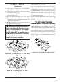
INSTALLATION FOR HORIZONTAL
TERMINATION
1. Determine the route your horizontal venting
will take. Note: The location of the horizontal
vent termination on the exterior wall must
meet all local and national building codes and
must not be blocked or obstructed.
WARNING: Do not recess
vent terminal into a wall or sid-
Snorkel terminations are available for termina-
tions requiring a vertical rise on the exterior of
the building (see Figures 12 and 13). Snorkel
kits are available for rigid pipe applications
only to provide a 14" rise and a 36" rise (see
page 17). Follow the same installation proce-
dures used for standard horizontal terminations.
If installing the snorkel termination to raise the
vent termination from below grade level such
as in a basement installation, you must provide
proper drainage to prevent water from entering
the snorkel termination (see Figure 13). Do not
back ll around the snorkel termination.
2. Rigid vent pipes and ttings have special
twist-lock connections. Assemble the desired
combination of pipe and elbows to the appli-
ance adaptor with pipe seams oriented towards
the wall or oor.
Figure 13 - Snorkel Termination with
Drainage Pipe
Figure 12 - Snorkel Termination
Snorkel
12" Minimum
90º
45º
Adequate
Drainage
Snorkel
12" Minimum
90º
45°
12"
Minimum
12"
Minimum

www.desatech.com
112108-01C12
VENTING INSTALLATION
INSTRUCTIONS
Continued
Figure 16 - Installing Horizontal Vent Cap
(Noncombustible Exterior)
Wood Screw
Vent Cap
Figure 17 - Installing Siding Standoff
(Combustible Exterior Wall)
Cut Siding Away to
Fit Standoff
Wood
Screw
Screws
Standoff
Vent
Cap
Apply Mastic
to All Four Sides
The female ends of the
pipes and ttings have four locking lugs (in-
dentations). These lugs will slide straight into
matching slots on the male ends of adjacent
pipes and ttings. (All connections must be
sealed with high temperature silicone sealant
as specied in the second warning statement
on page 10.) Push the pipe sections together
and twist one section clockwise approximately
one-quarter turn until the sections are fully
locked. See Figure 14. Note: Horizontal runs
of vent must be supported every three feet. Use
wall straps for this purpose.
3.
Attach vent pipe assembly to the replace using
twist lock connections. Set replace in front of
its permanent location to insure minimum clear-
ances. Mark the wall for a 10
3
/
4
" square hole (for
noncombustible material such as masonry block
or concrete, a 8
1
/
2
" diameter hole is acceptable).
See Figure 15. The center of the hole should
line up with the centerline of the rigid vent
pipe. Cut a 10
3
/
4
" x 10
3
/
4
" square hole through
combustible exterior wall (8
1
/
2
" diameter hole
if noncombustible). Frame as necessary.
4. Apply a bead
of non-hardening mastic around the outside
edge of the vent cap. Position the vent cap in the
center of the hole on the exterior wall with the
arrow on the vent cap pointing up. Attach the
vent cap with four wood screws provided (see
Figure 16). Note: Replace the wood screws
with appropriate fasteners for stucco, brick,
concrete, or other types of siding.
For vinyl siding,
stucco, or wood exteriors, a siding standoff
must be installed between the vent cap and
exterior wall. The siding standoff prevents
excessive heat from damaging siding materials.
Siding materials must be cut to accommodate
standoff. Bolt the vent cap to the standoff.
Apply non-hardening mastic around outside
edge of the standoff. Position the standoff/cap
assembly in the center of the square hole and
attach to exterior wall with wood screws pro-
vided (see Figure 17). The siding standoff must
sit ush against the exterior fascia material.
Figure 14 - Vent Pipe Connections
Male
Slots
Female
Locking
Lugs
Figure 15 - Vent Opening Requirements
(Framing
Detail)
10
3
/4"
10
3
/4" Inside Framing
10
3
/4"
8
1
/2"
Vent
O
pening
Combustible Wall
Vent Opening
Noncombustible Wall

www.desatech.com
112108-01C 13
Vent Cap
(Horizontal
Termination)
Interior Wall
Surface
Wall
Firestop
Horizontal
Vent Pipe
Figure 18 - Connecting Vent Cap with
Horizontal Vent Pipe
Screw
VENTING INSTALLATION
INSTRUCTIONS
Continued
5. Slide
interior wall restop over vent pipe before
connecting horizontal run to vent cap (see
Figure 18).
Figures 19 and 20 show different congurations for
venting with horizontal termination. Each gure
includes a chart with vertical minimum/maximum
and horizontal maximum dimensions which must
be met. All connections must be sealed with
high temperature silicone sealant as specied in
the second warning statement on page 11. All
horizontal terminations require 1/4" rise per 12"
of horizontal run. You must add 1/4" of vertical
height (V) in the following tables for each foot of
horizontal run (H).
Figure 19 - Horizontal Termination
Conguration for Rigid Venting Using
One 90° Elbow
Vertical (V) Horizontal (H)
49.5" min.* 17" max.*
60" min. 77" max.
72" min. 101" max.
84" min. 125" max.
132" min. 149" max.
(45° elbow, 1' vertical pipe, 90° elbow)
45° Starter
Elbow
Vertical (V) Horizontal (H1) +
Horizontal (H2)
5' min. 4' max.
6' min. 8' max.
7' min. 10' max.
8' min. 15' max.
20' max. 20' max.
Figure 20 - Horizontal Termination
Conguration for Rigid Venting Using
Two 90° Elbows with Termination at 90°
with Fireplace
45° Starter
Elbow

www.desatech.com
112108-01C14
VENTING INSTALLATION
INSTRUCTIONS
Continued
INSTALLATION FOR VERTICAL
TERMINATION
1. Determine the route your vertical venting will
take. If ceiling joists, roof rafters, or other
framing will obstruct the venting system,
consider an offset (see Figure 21) to avoid
cutting load bearing members.
Note: Pay special attention to these installa-
tion instructions for required clearances (air
space) to combustibles when passing through
ceilings, walls, roofs, enclosures, attic rafters,
etc. Do not pack air spaces with insulation.
Also note maximum vertical rise of the vent-
ing system and any maximum horizontal
offset limitations. Offsets must fall within the
parameters shown in Figure 22.
2. Set the replace in desired location. Drop a
plumb line down from the ceiling to the posi-
tion of the replace exit ue. Mark the center
point where the vent will penetrate the ceiling.
Drill a small locating hole at this point.
Drop a plumb line from the inside of the roof
to the locating hole in the ceiling. Mark the
center point where the vent will penetrate the
roof. Drill a small locating hole at this point.
X
12
Roof Pitch is
x 12 Listed
Clearance
8'
Minimum
Listed
Vent Cap
Lowest
Discharge
Opening
Listed
Gas
Vent
H (Min.) Height from Roof
Figure 22 - Vertical Vent Termination
Clearance
Flat to 6/12 1.0'
6/12 to 7/12 1.25'
Over 7/12 to 8/12 1.5'
Over 8/12 to 9/12 2.0'
Over 9/12 to 10/12 2.5'
Over 10/12 to 11/12 3.25'
Over 11/12 to 12/12 4.0'
Over 12/12 to 14/12 5.0'
Over 14/12 to 16/12 6.0'
Over 16/12 to 18/12 7.0'
Over 18/12 to 20/12 7.5'
Over 20/12 to 21/12 8.0'
Figure 21 - Vertical Vent Pipe Offsets
Plumber’s
Tape
Connected
to Wall
Strap
Wall
Strap
Firestop
(2) 45°
Elbows
Firestop
(2) 45°
Elbows
Roof
Flashing
1. Cut a 10
3
/
4
" square hole in the ceiling using
the locating hole as a center point. The open-
ing should be framed to 10
3
/
4
"x10
3
/
4
" inside
dimensions, as shown in Figure 18 on page
13 using framing lumber the same size as the
ceiling joists. If the area above the ceiling is an
insulated ceiling or an attic space, nail restop
from the top side. This prevents loose insula-
tion from falling into the required clearance
space. If the area above the ceiling is a living
space, install restop below the framed hole.
The restop should be installed with no less
than three nails per side (see Figure 23).
Figure 23 - Installing Firestop
If area above is a living space, install
restop below framed hole.
If area above is an attic, install restop
above framed hole.

www.desatech.com
112108-01C 15
VENTING INSTALLATION
INSTRUCTIONS
Continued
2.
Assemble the desired lengths of pipe and
elbows necessary to reach from the replace
ue up through the restop. All connections
must be sealed with high temperature silicone
sealant as specied in the second warning
statement on page 11. Be sure all pipe and
elbow connections are fully twist-locked (see
Figure 14, page 12 ).
3. Cut a hole in the roof using the locating hole
as a center point. (Cover any exposed open
vent pipes before cutting hole in roof.) The
10
3
/
4
" x 10
3
/
4
" hole must be measured on
the horizontal; actual length may be larger
depending on the pitch of the roof. There
must be a 1" clearance from the vent pipe to
combustible materials. Frame the opening as
shown in Figure 15 on page 12.
4. Connect a section of pipe and extend up
through the hole. If an offset is needed to avoid
obstructions, you must support the vent pipe
every 3 feet. Use wall straps for this purpose
(see Figure 21, page 14). Whenever possible,
use 45° elbows instead of 90° elbows. The 45°
elbow offers less restriction to the ow of the
ue gases and intake air.
5. Place the ashing over the pipe section(s)
extending through the roof. Apply a bead of
silicone or roof sealer to the bottom ange of
ashing and secure the base of the ashing to
the roof and framing with roong nails. Be
sure roong material overlaps the top edge of
the ashing as shown in Figure 21, page 14.
There must be a 1" clearance from the vent
pipe to combustible materials.
6. Continue to add pipe sections until the height
of the vent cap meets the minimum building
code requirements described in Figure 11,
page 9. Note: You must increase vent height
for steep roof pitches. Nearby trees, adjoining
rooines, steep pitched roofs, and other simi-
lar factors may cause poor draft or down-draft
condition (see Figure 22, page 14). Increasing
the vent height may solve this problem.
7. Apply a bead of sealer to the upper edge of
ashing collar. Slide storm collar over pipe and
down to top edge of ashing. Apply a second
bead of silicone or roof sealer around remain-
ing seam of storm collar. Twist-lock vent cap
onto last section of vent pipe and seal with
high temperature silicone sealant as specied
in the second warning statement on page 10.
Finish sealing ange around roong material
with roong sealer.
Figure 24 - Cathedral Ceiling Support
Box Installation
Cut hole 1/8"
larger than
support box when
projected onto rooine
2" minimum below
nished ceiling
Cathedral
ceiling
support box
Level
Note: If the vent pipe passes through any occupied
areas above the rst oor, including storage spaces
and closets, you must enclose pipe. You may frame
and sheetrock the enclosure with standard construc-
tion material. Make sure and meet the minimum
allowable clearances to combustibles. Do not ll
any of the required air spaces with insulation.
1. Remove shingles or other roof covering as
necessary to cut the rectangular hole for the
support box. Mark the outline of the cathedral
ceiling support box on the roof sheathing using
the locating hole as a center point.
2. Cut the hole 1/8" larger than the support box
outline (see Figure 24).
3. Lower the support box through the hole in the
roof until the bottom of the box extends at least
2" below the ceiling (see Figure 24). Align the
support box vertically and horizontally using
a level. Temporarily tack the support box in
place through the inside walls and into the roof
sheathing.
4. Using tin snips, cut the support box from the
top corners down to the rooine and fold the
resulting aps over the roof sheathing (see
Figure 25). Apply a bead of non-hardening
mastic around the top edges of the support box
to make a seal between the box and the roof.
Nail in place with roong nails. Remove any
combustible material that might be inside of
the support box.
Non-hardening
Mastic under all
edges of support
box before nailing
Figure 25 - Installed Cathedral Ceiling
Support Box

www.desatech.com
112108-01C16
Vertical Horizontal
(V
1
) (H)
5' min. 6' max.
6' min. 12' max.
7' min. 18' max.
8' min. 20' max.
Figure 28 - Vertical Rigid Venting
Conguration Using Two 90° Elbows
Vertical (V) Horizontal (H)
5' min. 2' max.
6' min. 4' max.
7' min. 6' max.
8' min. 8' max.
20' max. 8' max.
Figure 27 - Vertical Rigid Venting
Conguration Using One 90° Elbow
Vertical (V) Horizontal (H
1
) +
Horizontal (H
2
)
5' min. 2' max.
6' min. 4' max.
7' min. 6' max.
8' min. 8' max.
20' max. 8' max.
Figure 26 - Vertical Rigid Venting
Conguration Using Two 90° Elbows
with Two Horizontal Runs
5. Complete the cathedral ceiling installation
by following the same procedures outlined in
steps 2 through 7 for Flat Ceiling Installation,
page 14.
Figures 26 through 29 show four different congu-
rations for vertical termination. These minimum
vertical rises are based on horizontal runs with a
minimum of 1/4" upwards pitch per foot and do
not reect constraints on a vertical system with
45° or greater offset.
Any offset pitch of 45° or less must be considered
horizontal and sized within the maximum allow-
able lengths listed in the following examples. All
connections must be sealed with high temperature
silicone sealant as specied in the second warning
statement on page 10.
VENTING INSTALLATION
INSTRUCTIONS
Continued
45° Starter
Elbow
Note: Install
restrictor into inner
collar of replace
as shown.
45° Starter
Elbow
Note: Install
restrictor into
inner collar of
replace as
shown.
45° Starter
Elbow
Note: Install
restrictor into inner
collar of replace
as shown.

www.desatech.com
112108-01C 17
VENTING INSTALLATION
INSTRUCTIONS
Continued
Figure 29 - Vertical Rigid Venting
Conguration With No Horizontal Run
V = 40' max.
HIGH ALTITUDE INSTALLATION
Your DESA direct-vent replace has been tested
and approved for elevations from 0-2,000 feet and
certied for elevations from 0-5,000 feet.
Fireplaces for High Altitude (models ending in
HA) are for installation above 4,000 feet only.
These replaces are equipped with parts specic
for higher altitudes. IMPORTANT: These re-
places can NOT be converted to propane/LP gas.
When installing a non-high altitude replace at an
elevation above 2,000 feet (USA), you may need to
decrease the input rating by changing the existing
burner orice to a smaller size. Reduce input 4%
for each 1,000 feet above sea level. Check with
your local gas company for proper orice size
identication.
When installing this fireplace at an elevation
above 4,500 feet (Canada), check with local
authorities.
Consult with your local gas company to help de-
termine the proper orice size and identication
for your location.
Components and parts must be ordered by part
number through your local dealer or distributor.
IMPORTANT: For horizontal installations
above 2,000 feet, it is recommened that a 12"
extension pipe be added before starter elbow
(see Figure 30).
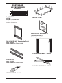
VKR-58 Roo f Ve nt K it , G al v an iz ed
(Includes: 45° Elbow, 7"-12"
Adjustable Pipe, Flue Restrictor,
Vertical High Wind Termination,
2' Pipe, 4' Pipe, Wall Firestop,
Storm Collar, Roof Flashing
[0/12 - 6/12], 26 Screws)
VKB-58 Basement Vent Kit, Galvanized
(Includes: 45° Elbow, 7"-12"
Adjustable Pipe, Wall Firestop,
Horizontal Square Termination,
4' Pipe, 90° Elbow, 20 Screws)
VKS-58 Snorkel Vent Kit, Galvanized
(Includes: 45° Elbow, 7"-12"
Adjustable Pipe, Wall Firestop,
36" Snorkel Termination, 4' Pipe,
1' Pipe, 90° Elbow, 26 Screws)
VKG-58 Ground Floor Vent Kit, Galvanized
(Includes: 45° Elbow, 7"-12"
Adjustable Pipe, Wall Firestop,
Horizontal Square Termination,
16 Screws)
P58-48 48" Section Double Wall Pipe,
Galvanized
P58-36 36" Section Double Wall Pipe,
Galvanized
P58-24 24" Section Double Wall Pipe,
Galvanized
P58-12 12" Section Double Wall Pipe,
Galvanized
P58-6 6" Section Double Wall Pipe,
Galvanized
PA58-712 Adjustable 7"-12" Section Double
Wall Pipe, Galvanized
FPA58-6 6" Dura Vent Collar to FMI Pipe
Adaptor
Figure 30 - Recommended 12" Extension
for High Altitude Installation
45° Starter
Elbow
Note: Install
restrictor into inner
collar of replace
as shown.
45° Starter
Elbow
12"
Extension

www.desatech.com
112108-01C18
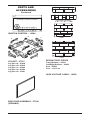
E58-45 45° Elbow, Galvanized
E58-90 90° Elbow, Galvanized
FSE58-45 45° Starter Elbow (Dura Vent to
FMI Pipe)
FP-58 Firestop Plate
WF-58 Wall Firestop, Galvanized
RF-58-6 Roof Flashing - 0 to 6/12 Pitch,
Galvanized
RF-58-12 Roof Flashing - 6/12 to 12/12 Pitch,
Galvanized
S-58 Vinyl Siding Standoff,
Galvanized
VT-58 Vertical Round Termination,
Galvanized
HHT-58 High WInd Round Horizontal
Termination Kit, Galvanized
HTS-58 Square Horizontal Termination,
Galvanized
HHTK-58 High Wind Round Horizontal
Termination Kit
(Includes Round Termination,
Wall Firestop, 45° Elbow)
ST-58-14 14" Snorkel Termination,
Galvanized
ST-58-36 36" Snorkel Termination,
Galvanized
SF-58 Stucco Flashing -
For use with HTS-58
VR-58 Vertical Restrictor, Galvanized
WS-58 Wall Strap
SC-58 Storm Collar, Galvanized
CS-58 Cathedral Ceiling Support
VENTING INSTALLATION
INSTRUCTIONS
Continued
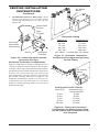
INSTALLATION
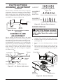
WALL SWITCH INSTALLATION
The electronic version uses a 24 VAC current sup-
plied from a transformer mounted on the ignition
module and is prewired for easy connection to a
wall switch (see Figure 31). The millivolt version
uses a self generated millivolt current that allows
you to activate the gas control valve directly with-
out the use of normal household electricity (see
Figure 32). Both versions are supplied with a wall
switch kit for ready connection and mounting.
WARNING: Do not wire re-
-
V1
SW
SI
TS
IND
V2
L1
D
N
G
P.
Figure 31 - Wall Switch Wiring Diagram,
Electronic Units
Route 24V (Supplied)
Through Electrical
Conduit Bushing
Electrode
Transformer
Plug 120V AC
To Receptacle
18 AWG
Red Wire
Wall Switch
(Supplied)
Make Connections
with Wirenuts
(Supplied)
Ignition
Control
Module
(Back
View)
V1
SW
SI
TS
IND
V2
L1
D
N
G
P.
Figure 32 - Wall Switch Wiring Diagram,
Millivolt Units
Note: If any of the original wire supplied must be
replaced, use type 18 AWG-105° C (25 feet length
maximum) or equivalent.
O
F
F
P
I
L
O
T
O
N
L
O
H
I
P
I
L
O
T
E A
16AI
7
TPTH TP TH
Wall Switch
(Supplied)
Route Millivolt Wires
(Supplied) Through Gas
Line Conduit Sleeve
To
Thermopile
(Back
View)
O
F
F
P
I
L
O
T
O
N
L
O
H
I
P
I
L
O
T
E A
16AI
7
TPTH TP TH
1. To remove the louvers, simultaneously pull
both top end spring latches towards the center
of the appliance until they are disengaged
from locating holes. Repeat for bottom spring
latches and pull louvers outward. Reverse the
procedure to install louvers back onto the ap-
pliance (see Figure 33, page 19).
2. Connect the 18 gauge wires from wall switch
to the gas control valve terminals marked TH
and TPTH or to the ignition module using the
pigtails and wire nut connectors supplied with
the appliance.

www.desatech.com
112108-01C 19
INSTALLATION
Continued
Figure 33 - Removing Louver
Glass
Locating
Holes
Spring Latch
Recommended
Blower Speed
Control
Location
Before blower accessory can be operated, the ap-
pliance outlet box must be properly connected to
a standard 120 VAC power source. This must be
done when the appliance is originally installed.
Refer to Wiring Diagrams on page 31.
An outlet box with two receptacles has been sup-
plied for your convenience and is located on the
lower right side of the appliance (see Figure 34).
The variable speed controller is mounted on a
magnetic base and may be positioned anywhere
within an accessible distance behind the louvered
opening (see Figure 33).
You may test the blower for operation by turning
the control knob clockwise just until it clicks on
which is the full on position. Adjust the fan speed
to the lowest setting (this should be no more than
1/4 of a turn clockwise).
Figure 34 - Connecting Blower
Accessory to Power Supply
For Optional
Fan Kit
From Blower
Assembly
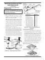
REMOTE CONTROL INSTALLATION
Note: If using an optional wireless hand-held
remote control, the wall switch is no longer
operational.
-
1. Remove lower louver access panel in re-
place (see step 1 of Wall Switch Installation,
page 18).
2. Disconnect wall switch wires from termi-
nals marked TH and TPTH (see Figure 32,
page 18).
3. Slide 9-volt battery into clip on back of remote
receiver and connect battery terminals to bat-
tery. Mount receiver onto bracket with clips
provided (see Figure 35).
4. Connect white wire to control valve terminal
TH and red wire to TPTH. Move remote select
switch to REMOTE position.
5. Replace louvered access panel by following
reverse of step 1 under Wall Switch Installa-
tion, page 18.
6. Remove battery cover on back of hand-held
remote (see Figure 36, page 20). Remove and
discard sensor tag.
7. Attach terminal wires to 9-volt battery. Place
battery into housing.
8. Replace battery cover onto hand-held remote.
9. Set selector switch on receiver to OFF posi-
tion if you will be away from the unit for an
extended period of time.
FRONT
O
F
F
P
I
L
O
T
O
N
L
O
H
I
P
I
L
O
T
E A
16AI
7
TPTH TP TH
Figure 35 - Installing Remote Receiver
(HRC100)
Gas
Valve
To Thermopile
Receiver Clip
Terminal
Wires
Plastic Mounting Clips
9-Volt Battery
White
Red
-

www.desatech.com
112108-01C20
INSTALLATION
Continued
1. Remove lower louver access panel in re-
place (see step 1 of Wall Switch Installation,
page 18).
2. If a wall switch was installed, it must be
removed from ignition control circuit for
remote to work properly. Remove wire nuts
from switch connection at ignition control
module. Using wire nut, connect transformer
(blue) wire to remaining wire connected to
control terminal marked P.SW (see Figure
36, page 18).
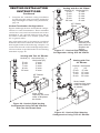
3. The receiver does not require a battery. To
install, plug extension cord into one of the
outlet receptacles on the outlet box. Plug re-
ceiver unit into extension cord and the ignition
module into receiver unit (see Figure 37).
4. Replace louvered access panel by following
reverse steps on page 18.
5. Activate handset battery by removing insulat-
ing tab on back (see Figure 38).
O
F
F
P
I
L
O
T
O
N
L
O
H
I
P
I
L
O
T
E A
16AI
7
TPTH TP TH
Gas
Valve
To Thermopile
Extension
Cord
Outlet Box
White
Red
Figure 37 - Installing Remote Receiver
(SKYTECH Model)
Optional Fan
Kit Plug
Receiver
Pull to Remove
Insulation Tab
Battery
Cover
12 Volt
Battery
Figure 38 - Installing Battery in Hand-
Held Remote Control Unit (SKYTECH)
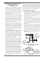
-
An equipment shutoff valve has been included in
the appliance’s gas supply system. You may con-
sider installing an extra gas shutoff valve outside
the appliance’s enclosure (check with local codes)
where it can be accessed more conveniently with a
key through a wall as shown in Figure 39.
Route a 1/2" NPT black iron gas line towards the
appliance coming in from the left. It is recom-
mended to route the pipe between the stand of
the rebox and the surround of the replace (see
Figure 40, page 21).
Figure 39 - Typical Exterior Wall Gas
Shutoff Installation
Key
Extension
Shutoff Valve
9-Volt Battery
Battery
Housing
Figure 36 - Installing Battery in Hand-
Held Remote Control Unit (HRC100)
Battery
Cover
Terminal
Wires
Remote Control Unit
Sensor
Tag
Page is loading ...
Page is loading ...
Page is loading ...
Page is loading ...
Page is loading ...
Page is loading ...
Page is loading ...
Page is loading ...
Page is loading ...
Page is loading ...
Page is loading ...
Page is loading ...
Page is loading ...
Page is loading ...
Page is loading ...
Page is loading ...
-
 1
1
-
 2
2
-
 3
3
-
 4
4
-
 5
5
-
 6
6
-
 7
7
-
 8
8
-
 9
9
-
 10
10
-
 11
11
-
 12
12
-
 13
13
-
 14
14
-
 15
15
-
 16
16
-
 17
17
-
 18
18
-
 19
19
-
 20
20
-
 21
21
-
 22
22
-
 23
23
-
 24
24
-
 25
25
-
 26
26
-
 27
27
-
 28
28
-
 29
29
-
 30
30
-
 31
31
-
 32
32
-
 33
33
-
 34
34
-
 35
35
-
 36
36


Ask a question and I''ll find the answer in the document
Finding information in a document is now easier with AI
Related papers
Other documents
-
Gibraltar Building Products RW26B Operating instructions
-
-
-
-
-
Gibraltar Building Products RW26G Operating instructions
-
-
-
-