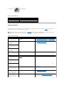
Dell PowerEdge 1600SC User manual
- Category
- Servers
- Type
- User manual
This manual is also suitable for

Dell™PowerEdge™1600SCSystemsInstallationandTroubleshooting
Guide
Introduction
Indicators, Codes, and Messages
Finding Software Solutions
Running the System Diagnostics
Troubleshooting Your System
Installing System Options
Installing Drives
Getting Help
Jumpers, Switches, and Connectors
I/O Ports and Connectors
Abbreviations and Acronyms
Information in this document is subject to change without notice.
©2003DellInc.Allrightsreserved.
Reproduction in any manner whatsoever without the written permission of Dell Inc. is strictly forbidden.
Trademarks used in this text: Dell, the DELL logo, PowerEdge, Dell OpenManage, DellNet, Dell Precision, Dimension, Inspiron, OptiPlex, and Latitude are trademarks of Dell Inc.; Intel is a
registered trademark of Intel Corporation; MS-DOS is a registered trademark of Microsoft Corporation.
Other trademarks and trade names may be used in this document to refer to either the entities claiming the marks and names or their products. Dell Inc. disclaims any
proprietary interest in trademarks and trade names other than its own.
Initial release: 22 Sep 2003
NOTE: A NOTE indicates important information that helps you make better use of your computer.
NOTICE: A NOTICE indicates either potential damage to hardware or loss of data and tells you how to avoid the problem.
CAUTION: A CAUTION indicates a potential for property damage, personal injury, or death.

Back to Contents Page
Jumpers, Switches, and Connectors
Dell™PowerEdge™1600SCSystemsInstallationandTroubleshootingGuide
Jumpers—A General Explanation
System Board Jumpers
System Board Connectors
Disabling a Forgotten Password
This section provides specific information about the system jumpers. It also provides some basic information on jumpers and switches and describes the
connectors on the various boards in the system.
Jumpers—A General Explanation
Jumpers provide a convenient and reversible way of reconfiguring the circuitry on a printed circuit board. When reconfiguring the system, you may need to
change jumper settings on circuit boards or drives.
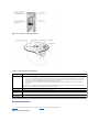
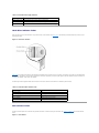
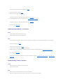
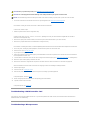
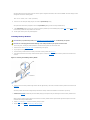
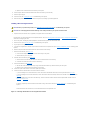
Jumpers
Jumpers are small blocks on a circuit board with two or more pins emerging from them. Plastic plugs containing a wire fit down over the pins. The wire connects
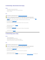
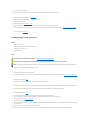
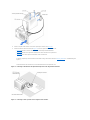
the pins and creates a circuit. To change a jumper setting, pull the plug off its pin(s) and carefully fit it down onto the pin(s) indicated. FigureA-1 shows an
example of a jumper.
Figure A-1. Example Jumpers
A jumper is referred to as open or unjumpered when the plug is pushed down over only one pin or if there is no plug at all. When the plug is pushed down
over two pins, the jumper is referred to as jumpered. The jumper setting is often shown in text as two numbers, such as 1–2. The number 1 is printed on the
circuit board so that you can identify each pin number based on the location of pin 1.
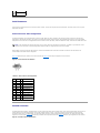
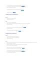
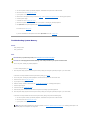
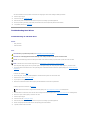
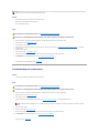
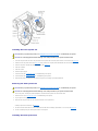
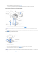
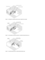
FigureA-2 shows the location and default settings of the system jumper blocks. See TableA-1 for the designations, default settings, and functions of the
system's jumpers.
System Board Jumpers
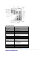
FigureA-2 shows the location of the configuration jumpers on the system board. TableA-1 lists the jumpers settings.
Figure A-2. System Board Jumpers
CAUTION: Ensure that the system is turned off before you change a jumper setting. Otherwise, damage to the system or unpredictable results
may occur.

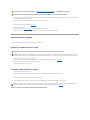
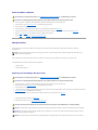
Table A-1.SystemBoardJumperSettings
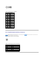
System Board Connectors
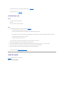
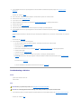
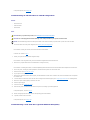
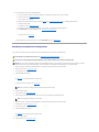
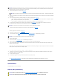
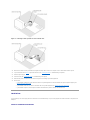
See FigureA-3 and TableA-2 for the location and description of system board connectors. FigureA-3 also indicates expansion slots and bus operating speeds.
Figure A-3. System Board Connectors
Jumper
Setting
Description
J11 pins 1 and
2
(default)
The password feature is enabled.
The password feature is disabled.
J11 pins 3 and
4
(default)
The configuration settings in NVRAM are retained at system boot.
The configuration settings in NVRAM are cleared at next system boot (see "Resetting Corrupted BIOS Configuration" in
"Troubleshooting Your System").
jumpered unjumpered

Table A-2. System Board Connectors
Disabling a Forgotten Password
Connector
Description
BATTERY
System battery
CHASSIS INTRUSION
Chassis intrusion switch
COM1/LPT/VGA
Serial, parallel, and video
CPUn
Microprocessors (2)
CPUn FAN
Microprocessor fan power (2)
DIMMx
Memory modules (4)
DRACIII/XT
Systems management
FDD
Diskette drive
FRONT PANEL
Front-panel switches and indicators
FRONT SYS FAN
Front system fan power
KB/MS
PS/2 keyboard and mouse
LAN
NIC
PRIMARY IDE
Primary IDE
PWR CONN
System board power
SCSI CONN
SCSI controller
SCSIB CONN
SCSI backplane
SECONDARY IDE
Secondary IDE
SLOTn
Expansion slots:
l 1–2: 64-bit/66-MHz PCI
l 3–4: 64-bit/100-MHz PCIX
l 5–6: 32-bit/33-MHz PCI
REAR SYS FAN
Back system fan power
USB
USB (2)
12V
System board power
NOTE: For the full name of an abbreviation or acronym used in this table, see "Abbreviations and Acronyms."

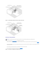
The system's software security features include a system password and a setup password, which are discussed in detail in "Using the System Setup Program"
in your User's Guide. The password jumper enables these password features or disables them and clears any password(s) currently in use.
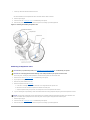
1. Turn off the system, including any attached peripherals, and disconnect the system from the electrical outlet.
2. Remove the cover (see "Removing the Cover" in "Troubleshooting Your System").
3. Lay the system on its right side.
4. Remove the password jumper plug.
See FigureA-2 to locate the password jumper on the system board.
5. Stand the system upright.
6. Install the cover (see "Installing the Cover" in "Troubleshooting Your System").
7. Reconnect the system to its electrical outlet and turn the system on, including any attached peripherals.
The existing passwords are not disabled (erased) until the system boots with the password jumper plug removed. However, before you assign a new
system and/or setup password, you must install the jumper plug.
8. Turn off the system, including any attached peripherals, and disconnect the system from the electrical outlet.
9. Remove the cover (see "Removing the Cover" in "Troubleshooting Your System").
10. Lay the system on its right side.
11. Install the password jumper plug.
See FigureA-2 to locate the password jumper on the system board.
12. Stand the system upright.
13. Install the cover (see "Installing the Cover" in "Troubleshooting Your System").
14. Reconnect the system to its electrical outlet and turn the system on, including any attached peripherals.
15. Assign a new system and/or setup password.
To assign a new password using the System Setup program, see "Using the System Setup Program" in your User's Guide.
Back to Contents Page
CAUTION: Before you perform this procedure, see "Safety First—For You and Your System" in "Troubleshooting Your System."
CAUTION: See "Protecting Against Electrostatic Discharge" in the safety instructions in your System Information Guide.
NOTE: If you assign a new system and/or setup password with the jumper plug still removed, the system disables the new password(s) the next
time it boots.

Back to Contents Page
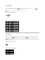
I/O Ports and Connectors
Dell™PowerEdge™1600SCSystemsInstallationandTroubleshootingGuide
I/O Connectors
Serial Connector
Parallel Connector
PS/2-Compatible Keyboard and Mouse Connectors
Video Connector
USB Connector
Integrated NIC Connector
Network Cable Requirements
I/O Connectors
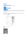
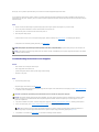
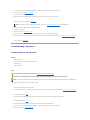
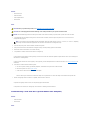
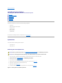
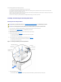
I/O connectors are the gateways that the system uses to communicate with external devices, such as a keyboard, mouse, printer, or monitor. This section
describes the various connectors on your system. If you reconfigure the hardware connected to the system, you may also need the pin number and signal
information for these connectors. FigureB-1 illustrates the connectors on the system.
Figure B-1. I/O Connectors
TableB-1 shows the icons used to label the connectors on the system.
Table B-1. I/O Connector Icons
Icon
Connector
Serial connector
Parallel connector
Mouse connector
Keyboard connector
Video connector
USB connector

Serial Connector
Serial connectors support devices such as external modems, printers, and mice that require serial data transmission. The serial connector uses a 9-pin D-
subminiature connector.
Serial Connector Autoconfiguration
The default designation of the integrated serial connector is COM1. When you add an expansion card containing a serial connector that has the same
designation as the integrated connector, the system's autoconfiguration feature remaps (reassigns) the integrated serial connector to the next available
designation. Both the new and the remapped COM connectors share the same IRQ setting. COM1 and COM3 share IRQ4, while COM2 and COM4 share IRQ3.
Before adding a card that remaps the COM connectors, check the documentation that came with the software to make sure that the software can
accommodate the new COM connector designation.
FigureB-2 illustrates the pin numbers for the serial connector and TableB-2 defines the pin assignments for the connector.
Figure B-2. Serial Connector Pin Numbers
Table B-2. Serial Connector Pin Assignments
Parallel Connector
The integrated parallel connector, intended primarily for use by printers that require data in parallel format, uses a 25-pin D-subminiature connector on the
system's back panel. The default designation of the system's parallel connector is LPT1. If you add an expansion card containing a parallel connector
configured as LPT1 (IRQ7, I/O address 378h), use the System Setup program to remap the integrated parallel connector. See "Using the System Setup
Program" in the User's Guide. FigureB-3 illustrates the pin numbers for the parallel connector and TableB-3 defines the pin assignments for the connector.
Figure B-3. Parallel Connector Pin Numbers
NIC connector
NOTE: If two COM connectors share an IRQ setting, you may not be able to use them both at the same time. In addition, if you install one or more
expansion cards with serial connectors designated as COM1 and COM3, the integrated serial connector is disabled.
Pin
Signal
I/O
Definition
1
DCD
I
Data carrier detect
2
SIN
I
Serial input
3
SOUT
O
Serial output
4
DTR
O
Data terminal ready
5
GND
N/A
Signal ground
6
DSR
I
Data set ready
7
RTS
O
Request to send
8
CTS
I
Clear to send
9
RI
I
Ring indicator
Shell
N/A
N/A
Chassis ground

Table B-3. Parallel Connector Pin Assignments
PS/2-Compatible Keyboard and Mouse Connectors
The PS/2-compatible keyboard and mouse cables attach to 6-pin, miniature DIN connectors. FigureB-4 illustrates the pin numbers for these connectors and
TableB-4 defines the pin assignments for these connectors.
Figure B-4. Keyboard and Mouse Connector Pin Numbers
Table B-4. Keyboard and Mouse Connector Pin Assignments
Pin
Signal
I/O
Definition
1
STB#
I/O
Strobe
2
PD0
I/O
Printer data bit 0
3
PD1
I/O
Printer data bit 1
4
PD2
I/O
Printer data bit 2
5
PD3
I/O
Printer data bit 3
6
PD4
I/O
Printer data bit 4
7
PD5
I/O
Printer data bit 5
8
PD6
I/O
Printer data bit 6
9
PD7
I/O
Printer data bit 7
10
ACK#
I
Acknowledge
11
BUSY
I
Busy
12
PE
I
Paper end
13
SLCT
I
Select
14
AFD#
O
Automatic feed
15
ERR#
I
Error
16
INIT#
O
Initialize printer
17
SLIN#
O
Select in
18–25
GND
N/A
Ground
Pin
Signal
I/O
Definition
1
KBDATA or MFDATA
I/O
Keyboard data or mouse data
2
NC
N/A
No connection
3
GND
N/A
Signal ground
4
FVcc
N/A
Fused supply voltage
5
KBCLK or MFCLK
I/O
Keyboard clock or mouse clock
6
NC
N/A
No connection
Shell
N/A
N/A
Chassis ground

Video Connector
You can attach a VGA-compatible monitor to the system's integrated video controller using a 15-pin high-density D-subminiature connector. FigureB-5
illustrates the pin numbers for the video connector and TableB-5 defines the pin assignments for the connector.
Figure B-5. Video Connector Pin Numbers
Table B-5. Video Connector Pin Assignments
USB Connector
The system's USB connector supports USB-compliant peripherals such as keyboards, mice, and printers and may also support USB-compliant devices such as
diskette drives and CD drives. FigureB-6 illustrates the pin numbers for the USB connector and TableB-6 defines the pin assignments for the connector.
Figure B-6. USB Connector Pin Numbers
Table B-6. USB Connector Pin Assignments
NOTE: Installing a video card automatically disables the system's integrated video controller.
Pin
Signal
I/O
Definition
1
RED
O
Red video
2
GREEN
O
Green video
3
BLUE
O
Blue video
4
NC
N/A
No connection
5–8, 10
GND
N/A
Signal ground
9
VCC
N/A
Vcc
11
NC
N/A
No connection
12
DDC data out
O
Monitor detect data
13
HSYNC
O
Horizontal synchronization
14
VSYNC
O
Vertical synchronization
15
NC
N/A
No connection
NOTICE: Do not attach a USB device or a combination of USB devices that draw a maximum current of more than 500 mA per channel or +5 V. Attaching
devices that exceed this threshold may cause the USB connectors to shut down. See the documentation that accompanied the USB devices for their
maximum current ratings.
Pin
Signal
I/O
Definition
1
Vcc
N/A
Supply voltage
2
DATA
I
Data in
3
+DATA
O
Data out
4
GND
N/A
Signal ground

Integrated NIC Connector
The system's integrated NIC functions as a separate network expansion card while providing fast communication between servers and workstations. FigureB-
7 illustrates the pin numbers for the NIC connector and TableB-7 defines the pin assignments for the connector.
Figure B-7. NIC Connector
Table B-7. NIC Connector Pin Assignments
Network Cable Requirements
The NIC supports a UTP Ethernet cable equipped with a standard RJ45-compatible plug. Observe the following cabling restrictions.
l Use Category 5 or greater wiring and connectors.
l Do not exceed a cable run length (from a workstation to a hub) of 100 m (328 ft).
For detailed guidelines on operation of a network, see "Systems Considerations of Multi-Segment Networks" in the IEEE 802.3 standard.
Back to Contents Page
Pin
Signal
I/O
Definition
1
TD+
O
Data out (+)
2
TD–
O
Data out (–)
3
RD+
I
Data in (+)
4
NC
N/A
No connection
5
NC
N/A
No connection
6
RD–
I
Data in (–)
7
NC
N/A
No connection
8
NC
N/A
No connection
NOTICE: To avoid line interference, voice and data lines must be in separate sheaths.

Back to Contents Page
Abbreviations and Acronyms
Dell™PowerEdge™1600SCSystemsInstallationandTroubleshootingGuide
A
ampere(s)
AC
alternating current
ADC
analog-to-digital converter
ANSI
American National Standards Institute
APIC
Advanced Peripheral Interrupt Controller
ASIC
application-specific integrated circuit
BIOS
basic input/output system
BMC
baseboard management controller
bpi
bits per inch
bps
bits per second
BTU
British thermal unit
C
Celsius

CD
compact disc
CGA
color graphics adapter
cm
centimeter(s)
CMOS
complementary metal oxide semiconductor
COM
communications
cpi
characters per inch
cpl
characters per line
CPU
central processing unit
DAC
digital-to-analog converter
DAT
digital audio tape
dB
decibel(s)
dBA
adjusted decibel(s)
DC
direct current
DDR
double-data rate

DIMM
dual in-line memory module
DIN
Deutsche Industrie Norm
DIP
dual in-line package
DMA
direct memory access
DOC
Department of Communications (in Canada)
dpi
dots per inch
DRAC III
remote access card
DRAM
dynamic random-access memory
DS/DD
double-sided double-density
DS/HD
double-sided high-density
ECC
error checking and correction
EDO
extended-data out
EGA
enhanced graphics adapter
EIDE

enhanced integrated drive electronics
EMI
electromagnetic interference
EMM
expanded memory manager
EMS
Expanded Memory Specification
EPP
Enhanced Parallel Port
EPROM
erasable programmable read-only memory
ERA
embedded remote access
ESD
electrostatic discharge
ESDI
enhanced small-device interface
ESM
embedded server management
F
Fahrenheit
FAT
file allocation table
FCC
Federal Communications Commission
ft
feet

g
gram(s)
G
gravities
GB
gigabyte(s)
GUI
graphical user interface
Hz
hertz
I/O
input/output
ID
identification
IDE
integrated drive electronics
IRQ
interrupt request
K
kilo- (1024)
KB
kilobyte(s)
KB/sec
kilobyte(s) per second
Kb
kilobit(s)
Kbps
kilobit(s) per second

kg
kilogram(s)
kHz
kilohertz
LAN
local area network
lb
pound(s)
LCD
liquid crystal display
LED
light-emitting diode
LIF
low insertion force
LN
load number
lpi
lines per inch
LVD
low voltage differential
m
meter(s)
mA
milliampere(s)
mAh
milliampere-hour(s)
MB
megabyte(s)

Mb
megabit(s)
Mbps
megabit(s) per second
MBR
master boot record
MDA
monochrome display adapter
MGA
monochrome graphics adapter
MHz
megahertz
mm
millimeter(s)
ms
millisecond(s)
MTBF
mean time between failures
mV
millivolt(s)
NIC
network interface controller
NiCad
nickel cadmium
NiMH
nickel-metal hydride
NMI

nonmaskable interrupt
ns
nanosecond(s)
NTFS
NT File System
NVRAM
nonvolatile random-access memory
OTP
one-time programmable
PAL
programmable array logic
PCI
Peripheral Component Interconnect
PCMCIA
Personal Computer Memory Card International Association
PDB
power distribution board
PDU
power distribution unit
PGA
pin grid array
PIC
personal identification code
POST
power-on self-test
ppm
pages per minute

PQFP
plastic quad flat pack
PSDB
power-supply distribution board
PS/2
Personal System/2
PXE
preboot execution environment
RAID
redundant arrays of independent disks
RAC
remote access controller
RAM
random-access memory
RCU
Resource Configuration Utility
REN
ringer equivalence number
RFI
radio frequency interference
RGB
red/green/blue
ROM
read-only memory
rpm
revolutions per minute
RTC
real-time clock

SBE
single bit ECC
SCSI
small computer system interface
sec
second(s)
SEC
single-edge contact
SEL
system event log
SDRAM
synchronous dynamic random-access memory
SIMM
single in-line memory module
SMB
server management bus
SMI
system management interrupt
SNMP
Simple Network Management Protocol
SRAM
static random-access memory
SVGA
super video graphics array
TFT
thin film transistor
tpi
tracks per inch
Page is loading ...
Page is loading ...
Page is loading ...
Page is loading ...
Page is loading ...
Page is loading ...
Page is loading ...
Page is loading ...
Page is loading ...
Page is loading ...
Page is loading ...
Page is loading ...
Page is loading ...
Page is loading ...
Page is loading ...
Page is loading ...
Page is loading ...
Page is loading ...
Page is loading ...
Page is loading ...
Page is loading ...
Page is loading ...
Page is loading ...
Page is loading ...
Page is loading ...
Page is loading ...
Page is loading ...
Page is loading ...
Page is loading ...
Page is loading ...
Page is loading ...
Page is loading ...
Page is loading ...
Page is loading ...
Page is loading ...
Page is loading ...
Page is loading ...
Page is loading ...
Page is loading ...
Page is loading ...
Page is loading ...
Page is loading ...
Page is loading ...
Page is loading ...
Page is loading ...
Page is loading ...
Page is loading ...
Page is loading ...
Page is loading ...
Page is loading ...
Page is loading ...
Page is loading ...
Page is loading ...
Page is loading ...
Page is loading ...
Page is loading ...
Page is loading ...
Page is loading ...
Page is loading ...
Page is loading ...
Page is loading ...
Page is loading ...
Page is loading ...
Page is loading ...
Page is loading ...
Page is loading ...
Page is loading ...
Page is loading ...
Page is loading ...
Page is loading ...
Page is loading ...
Page is loading ...
Page is loading ...
Page is loading ...
Page is loading ...
Page is loading ...
Page is loading ...
Page is loading ...
Page is loading ...
Page is loading ...
-
 1
1
-
 2
2
-
 3
3
-
 4
4
-
 5
5
-
 6
6
-
 7
7
-
 8
8
-
 9
9
-
 10
10
-
 11
11
-
 12
12
-
 13
13
-
 14
14
-
 15
15
-
 16
16
-
 17
17
-
 18
18
-
 19
19
-
 20
20
-
 21
21
-
 22
22
-
 23
23
-
 24
24
-
 25
25
-
 26
26
-
 27
27
-
 28
28
-
 29
29
-
 30
30
-
 31
31
-
 32
32
-
 33
33
-
 34
34
-
 35
35
-
 36
36
-
 37
37
-
 38
38
-
 39
39
-
 40
40
-
 41
41
-
 42
42
-
 43
43
-
 44
44
-
 45
45
-
 46
46
-
 47
47
-
 48
48
-
 49
49
-
 50
50
-
 51
51
-
 52
52
-
 53
53
-
 54
54
-
 55
55
-
 56
56
-
 57
57
-
 58
58
-
 59
59
-
 60
60
-
 61
61
-
 62
62
-
 63
63
-
 64
64
-
 65
65
-
 66
66
-
 67
67
-
 68
68
-
 69
69
-
 70
70
-
 71
71
-
 72
72
-
 73
73
-
 74
74
-
 75
75
-
 76
76
-
 77
77
-
 78
78
-
 79
79
-
 80
80
-
 81
81
-
 82
82
-
 83
83
-
 84
84
-
 85
85
-
 86
86
-
 87
87
-
 88
88
-
 89
89
-
 90
90
-
 91
91
-
 92
92
-
 93
93
-
 94
94
-
 95
95
-
 96
96
-
 97
97
-
 98
98
-
 99
99
-
 100
100


Dell PowerEdge 1600SC User manual
- Category
- Servers
- Type
- User manual
- This manual is also suitable for
Ask a question and I''ll find the answer in the document
Finding information in a document is now easier with AI
Related papers
-
Dell PowerVault 132T LTO/SDLT (Tape Library) Owner's manual
-
-
Dell Latitude D400 Owner's manual
-
Dell PowerEdge 850 User guide
-
-
Dell PowerEdge 750 User guide
-
-
Dell PowerEdge 2800 User guide
-
Dell PowerEdge 2650 Owner's manual
-
Dell PowerEdge 2600 User manual