5
Setup
1
0
Setup function Settings & options (factory settings in bold)
1 System type
TH3110D only
0 Gas, oil or electric heat with air conditioning
1 Heat pump (5 minute compressor off time in heating and cool-
ing)
5 Heating cycle rate
(CPH: cycles/hour)
TH3110D only
5 For gas or oil furnaces of less than 90% efficiency
1 For steam or gravity systems
3 For hot water systems & furnaces of over 90% efficiency
9 For electric furnaces
[Other cycle rate options: 2, 4, 6, 7, 8, 10, 11 or 12 CPH]
6 Auxiliary heat
cycle rate (CPH)
TH3210D only
5 For gas or oil furnaces of less than 90% efficiency
1 For steam or gravity systems
3 For hot water systems & furnaces of over 90% efficiency
9 For electric furnaces
[Other cycle rate options: 2, 4, 6, 7, 8, 10, 11 or 12 CPH]
8 Emergency heat
cycle rate (CPH)
TH3210D only
9 For electric emergency heat
1 For steam or gravity systems
3 For hot water systems & furnaces of over 90% efficiency
5 For gas or oil furnaces of less than 90% efficiency
[Other cycle rate options: 2, 4, 6, 7, 8, 10, 11 or 12 CPH]
9 Compressor
cycle rate (CPH)
3 Recommended for most compressors
[Other cycle rate options: 1, 2, 4, 5, or 6 CPH]
14 Temperature
display
0 Fahrenheit
1 Celsius
15 Compressor
protection
5 Five-minute compressor off time
[Other options: 0, 1, 2, 3 or 4-minute off time]
Compressor Protection (Setup Function 15): Forces the compressor to wait a few minutes before
restarting, to prevent damage. During the wait time, the message Cool On or Heat On (heat pumps
only) will flash on the display.
Follow the procedure below to configure
the thermostat to match the installed
heating/cooling system, and customize
feature operation as desired.
To begin, press and hold the
s and t
buttons until the display changes.
• Press
t to change settings.
• Press
s to advance to next
function.
• Press and hold
ts to exit and
save settings.
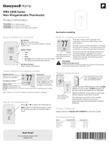
Installer Setup
Function
number
Setting