Maytag MHWE201YW Installation guide

Type
Installation guide
W10408696B
W10409178B - SP
WASHER
INSTALLATION
INSTRUCTIONS
Table of Contents
WASHER SAFETY .........................................................1
INSTALLATION REQUIREMENTS ................................2
Tools and Parts ................................................................ 2
Alternative Parts ..............................................................2
Location Requirements ..................................................3
Drain System ...................................................................4
Electrical Requirements .................................................5
INSTALLATION INSTRUCTIONS ..................................5
Connect Drain Hose ........................................................ 6
Connect Inlet Hoses ........................................................7
Level Washer ...................................................................8
Complete Installation Checklist .....................................9
WASHER SAFETY
INSTALLATION NOTES
Date of purchase: _________________________________
Date of installation: _______________________________
Installer: ________________________________________
Model number: ___________________________________
Serial number: ___________________________________
NOTES SUR L’INSTALLATION
Date d’achat : ____________________________________
Date d’installation : _______________________________
Installateur : _____________________________________
Numéro de modèle : _______________________________
Numéro de série : _________________________________
Table des matières
SÉCURITÉ DE LA LAVEUSE ......................................10
EXIGENCES D’INSTALLATION ..................................10
Outillage et pièces ........................................................10
Autres pièces .................................................................10
Exigences d’emplacement ...........................................11
Système de vidange ...................................................... 13
Spécications électriques ............................................ 13
INSTRUCTIONS D’INSTALLATION ............................14
Raccordement du tuyau de vidange............................15
Raccordement des tuyaux d’arrivée d’eau .................16
Établissement de l’aplomb de la laveuse ....................17
Liste de vérication pour l’achèvement
de l’installation ..............................................................19
INSTRUCTIONS
D’INSTALLATION
DE LA LAVEUSE
2
Optional tools:
Parts supplied:
NOTE: All parts supplied for installation are in the washer
basket.
4" min
(102 mm)
Wood block
Adjustable or open end
wrenches
1
2
" (13 mm) and
9
16
" (14 mm)
Ruler or measuring tape
Level
Pliers that open to 1
9
16
"
(39.5 mm)
Flashlight Bucket
Beaded tie strap
Drain hose
INSTALLATION REQUIREMENTS
Tools and Parts
Gather required tools and parts before starting installation.
Tools needed:
Transport bolt hole
plugs (Quantity will vary,
depending on model.)
Alternative Inlet Hoses:
(may be required for some installations, not supplied
with washer)
n
8212656RP 10 ft (3.0 m) Inlet hose, Black EPDM (2 pack)
n
8212641RP 5 ft (1.5 m) Inlet hose, Black EPDM (2 pack)
n
8212546RP 4 ft (1.2 m) Inlet hose, Black EPDM (2 pack)
n
8212545RP 5 ft (1.5 m) Inlet hose, Red and Blue EPDM
(2 pack)
n
8212487RP 5 ft (1.5 m) Nylon braided inlet hose (2 pack)
n
8212638RP 6 ft (1.8 m) Nylon braided inlet hose, space
saving 90° elbow, hypro-blue steel couplings
(2 pack)
n
8212637RP 6 ft (1.8 m) Inlet hose, Black EPDM, space
saving 90° elbow, hypro-blue steel couplings
(2 pack)
Available Accessories:
An optional matching pedestal is available for your washer.
Please contact your retailer for ordering information, or see
the Assistance or Service page on the back of your Use and
Care Guide.
Alternative parts
(Not supplied with washer)
Your installation may require additional parts. To order, please
refer to toll-free numbers on the back page of your Use and
Care Guide.
If you have: You will need:
Laundry tub or Sump pump system
standpipe taller than (if not already available)
96" (2.4 m)
Overhead sewer Standard 20 gal. (76 L) 30" (762 mm)
tall drain tub or utility sink and sump
pump (available from local plumbing
suppliers)
1" (25 mm) standpipe 2" (51 mm) diameter to 1" (25 mm)
diameter Standpipe Adapter
Part Number 3363920
Connect Kit Part Number 285835
Floor drain system Siphon Break Part Number 285834;
additional Drain Hose,
Part Number 8318155; and Connector
Kit, Part Number 285835
Drain hose too short Extension Drain Hose
Part Number 285863
Water faucets beyond 2 longer water ll hoses;
reach of ll hoses 6 ft (1.8 m) Part Number 76314
10 ft (3.0 m) Part Number 350008
Drain hose form and hose
clamp
Inlet hoses (2) with
washers (4)
Parts needed: (Not supplied with washer)
3
LOCATION REQUIREMENTS
Proper installation is your responsibility.
You will need:
n
A water heater set to 120° F (49° C).
n
A grounded electrical outlet located within 6 ft (1.8 m) of
power cord on back of washer.
n
Hot and cold water faucets located within 4 ft (1.2 m) of hot
and cold water ll valves on washer, and water pressure of
20-100 psi (137.9-689.6 kPa).
n
A level oor with maximum slope of 1" (25 mm) under entire
washer. Installing on carpet or surfaces with foam backing is
not recommended.
n
Floor must support washer’s total weight (with water and load)
of 400 lbs (180 kgs).
IMPORTANT: Do not install, store, or operate washer where
it will be exposed to weather or in temperatures below 32° F
(0° C). Water remaining in washer after use may cause damage
in low temperatures. See “Washer Care” in Washer Use and Care
Guide for winterizing information.
All dimensions show recommended spacing allowed, except for
closet door ventilation openings which are the minimum required.
For each arrangement, consider allowing more space for ease of
installation and servicing, and spacing for companion appliances
and clearances for walls, doors, and oor moldings.
Space must be large enough to allow door to fully open.
Add spacing of 1" (25 mm) on all sides of washer to reduce
noise transfer. If a closet door or louvered door is installed, top
and bottom air openings in door are required.
Recessed area or closet installation
(stacked washer and dryer):
30
1
/2"
(775 mm)
27"
(686 mm)
36"
(914 mm)
50
1
/4"
(1276 mm)
1"
(25 mm)
1"
(25 mm)
36" min.
(914 mm)
2"
(50 mm)
Custom under counter installation:
Recessed area or closet installation (washer only):
48" min.
(1220 mm)
1"
(25 mm)
4"
(102 mm)
24 in.
2
(155 cm
2
)
48 in.
2
(310 cm
2
)
3"
(76 mm)
3"
(76 mm)
1"
(25 mm)
1"
(25 mm)
5
1
/4"
(133 mm)
24 in.
2
(155 cm
2
)
48 in.
2
(310 cm
2
)
3"
(76 mm)
3"
(76 mm)
72"
(1829 mm)
12"
(305 mm)
1"
(25 mm)
1"
(25 mm)
4"
(102 mm)
24
" min.
(610 mm)
38" min.
(965 mm)
1"
(25 mm)
Recessed or closet installation (washer on pedestal):
4
Floor drain system requires a Siphon Break Kit (Part Number
285834), 2 Connector Kits (Part Number 285835), and an
Extension Drain Hose (Part Number 285863) that may be
purchased separately. See “Alternative Parts”. Minimum siphon
break height: 28" (710 mm) from bottom of washer. (Additional
hoses may be needed.)
30"
(762 mm)
28"
(710 mm)
Minimum diameter for a standpipe drain: 2" (51 mm). Minimum
carry-away capacity: 17 gal. (64 L) per minute. A 1/4" (6 mm)
diameter to 1" (25 mm) diameter Standpipe Adapter Kit is
available (Part Number 3363920). Top of standpipe must be
at least 30" (762 mm) high; install no higher than 96" (2.4 m)
from bottom of washer. If you have an overhead sewer and
need to pump higher than 96 inches, a sump pump and
associated hardware are needed. See “Alternative Parts”.
Minimum capacity: 20 gal. (76 L). Top of laundry tub must
be at least 30" (762 mm) above oor; install no higher than
96" (2.4 m) from bottom of washer.
Floor drain system
30"
(762 mm)
4
1
/2"
(113 mm)
4
1
/2"
(113 mm)
30"
(762 mm)
30"
(762 mm)
DRAIN SYSTEM
Drain system can be installed using a oor drain, wall standpipe,
oor standpipe, or laundry tub. Select method you need.
IMPORTANT: To avoid siphoning, only 4
1
/
2
" (113 mm) of drain
hose should be inside standpipe. Always secure drain hose with
beaded tie strap.
Floor standpipe drain system
7"
(178 mm)
1"
(25 mm)
4"
(102 mm)
9"
(229 mm)
1"
(25 mm)
Custom cabinet installation: Wall standpipe drain system
4
1
/2"
(113 mm)
See requirements for oor standpipe drain system.
Laundry tub drain system
5
INSTALLATION
INSTRUCTIONS
NOTE: To avoid oor damage, set washer onto cardboard
before moving it.
It is necessary to remove all shipping materials for proper
operation and to avoid excessive noise from washer.
Move washer to within 36" (914 mm) of its nal location. It must
be in a fully upright position.
ELECTRICAL REQUIREMENTS
n
A 120 volt, 60 Hz., AC only, 15- or 20-amp, fused electrical
supply is required. A time-delay fuse or circuit breaker is
recommended. It is recommended that a separate circuit
breaker serving only this appliance be provided.
n
This washer is equipped with a power supply cord having
a 3 prong grounding plug.
n
To minimize possible shock hazard, the cord must be plugged
into a mating, 3 prong, grounding-type outlet, grounded in
accordance with local codes and ordinances. If a mating outlet
is not available, it is the personal responsibility and obligation
of the customer to have the properly grounded outlet installed
by a qualied electrician.
n
If codes permit and a separate ground wire is used, it is
recommended that a qualied electrician determine that
the ground path is adequate.
n
Do not ground to a gas pipe.
n
Check with a qualied electrician if you are not sure the
washer is properly grounded.
n
Do not have a fuse in the neutral or ground circuit.
Locate all transport bolts on rear of washer (quantity may vary,
depending on model).
1. Move washer
48"
(1.2 m)
2. Locate transport bolts
6
Loosen bolts with a 13 mm (1/2") wrench.
Slide each bolt and spacer to center of hole. Pull bolts and
plastic spacers from back of washer. Save transport bolts
and spacers. Contact a qualied servicer if washer is to be
transported.
Close bolt holes on cabinet back with transport bolt hole plugs
included with washer parts.
Pull power cord through opening in rear panel and close
holes (2) with attached white plastic cap.
NOTE: If washer is transported at a later date, call a certied
technician to properly set up washer for relocation, to avoid
suspension and structural damage.
CONNECT DRAIN HOSE
Gently place power cord over top of washer to allow free
access to back of washer.
Squeeze hose clamp tabs with pliers and slide over end of
drain hose. Slide drain hose onto washer elbow connector
and secure with clamp.
For a laundry tub or standpipe drain, go to step 8.
You may need additional parts with separate directions.
See Floor drain system under “Alternative Parts”.
3. Remove transport bolts from
washer
4. Cover bolt holes with transport
bolt hole plugs
6. Place power cord over top
5. Remove power cord
7. Attach drain hose to drain port
7
Run water through both faucets and inlet hoses, into a laundry
tub, drainpipe, or bucket, to get rid of particles in the water
lines.
Check the temperature of the water to make sure that the hot
water hose is connected to the hot water faucet and that the
cold water hose is connected to the cold water faucet.
Snap either end of the drain hose form to the drain hose at the
point where the corrugation begins (A). Bend the drain hose to
form and snap into place (B).
Place hose into standpipe (shown in picture) or over side of
laundry tub.
IMPORTANT: Only 4
1
/
2
" (113 mm) of drain hose should be
inside standpipe; do not force excess hose into standpipe or
lay on bottom of laundry tub. Drain hose form must be used.
CONNECT INLET HOSES
Insert new at washers (supplied) into each end of the inlet
hoses. Firmly seat the washers in the couplings.
Attach hose to hot water faucet. Screw on coupling by hand
until it is seated on washer. Use pliers to tighten couplings an
additional two-thirds turn. Repeat this step with second hose
for cold water faucet.
IMPORTANT: Do not overtighten or use tape or sealants on
valve when attaching to faucets or washer. Damage can result.
HELPFUL TIP: Make note of which hose is connected to hot
water to help in attaching hoses to washer correctly. In most
standard congurations, hoses will cross over each other when
attached correctly.
Washer must be connected to water faucets with new inlet
hoses (A) with at washers (B) (not provided). Do not use old
hoses.
NOTE: Both hoses must be attached and have water owing
to inlet valves. For optimal performance, hot and cold water
must be supplied to the washer.
9. Place drain hose in standpipe
4.5"
(113 mm)
Drain
hose form
8. Connect drain hose form
A B
10. Connect washer into inlet hose
A B
11. Connect inlet hoses to water
faucets
12. Clear water lines
8
LEVEL WASHER
Leveling your washer properly reduces excess noise and
vibration.
NOTE: Installing washer on soft oor surfaces, such as
carpets or surfaces with foam backing, is not recommended.
Remove cardboard from beneath washer.
Slide washer to its nal location. Place a level on top edges
of washer, checking each side and front. If not level, tip
washer and adjust feet up or down as shown in steps 17
and 18, repeating as necessary. If washer is against a wall,
move out slightly before tipping back.
Grip washer from top and rock back and forth, making sure all
four feet are rmly on oor. Repeat, rocking washer from side
to side. If washer rocks, go to step 18 and adjust leveling feet.
If all four feet are in rm contact with oor, go to Step 19.
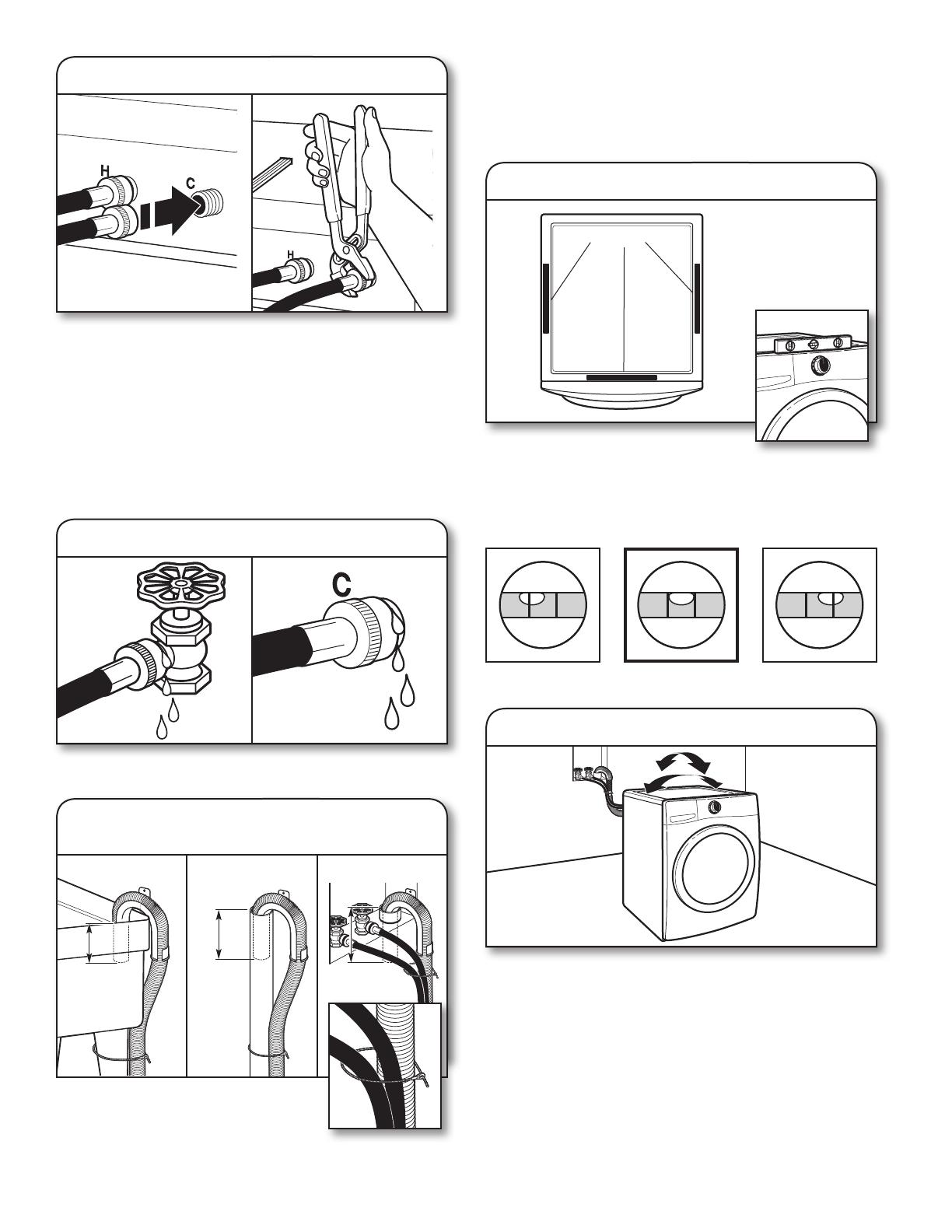
Not Level LEVEL Not Level
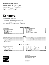
Attach hot water hose to hot water inlet valve marked with a
red valve. Screw coupling by hand until it is snug. Use pliers
to tighten couplings an additional two-thirds turn. Repeat with
cold water inlet valve.
IMPORTANT: To reduce risk of hose failure, replace the hoses
every 5 years. Record hose installation or replacement dates
for future reference.
n
Do not overtighten or use tape or sealants on the valve.
Damage to the valves can result.
n
Periodically inspect and replace hoses if bulges, kinks, cuts,
wear, or leaks are found.
Slowly turn on water faucets to check for leaks. A small
amount of water may enter washer. It will drain later.
13. Connect inlet hoses to washer
14. Turn faucets on and check for leaks
15. Secure drain hose with
beaded tie strap
4
1
/2"
(113 mm)
4
1
/2"
(113 mm)
4
1
/2"
(113 mm)
Laundry Tub Standpipe Wall
16. Check levelness of washer
place level here
17. Rock washer to test foot contact
Secure drain hose to laundry tub leg, drain
standpipe, or inlet hoses for wall standpipe
with beaded tie strap located in parts bag.
To avoid siphoning, do not seal or put more than
4
1
/
2
" (113 mm) of the drain hose into drainpipe or standpipe.
9
COMPLETE INSTALLATION
CHECKLIST
q
Check electrical requirements. Be sure you have correct
electrical supply and recommended grounding method.
q
Check that all parts supplied are now installed. If there is an
extra part, go back through steps to see what was skipped.
q
Check that you have all of your tools.
q
Check that transport bolts and plastic spacer materials were
completely removed from back of washer.
q
Check that both hot and cold hoses are attached and water
faucets are on.
q
Check for leaks around faucets, valves, and inlet hoses.
q
Remove protective lm, tape, or any packaging material
remaining on washer.
q
Check that washer is plugged into a grounded 3 prong
outlet.
q
Dispose of/recycle all packaging materials.
q
Read “Using Your Washer” in your Washer Use and Care
Guide.
q
To test and clean your washer, press POWER and choose
the NORMAL cycle and run it without clothes. Use only HE
detergent. Use 1/2 the manufacturer’s recommended amount
for a medium-size load.
If washer is not level, use a 9/16" or 14 mm open-end or
adjustable wrench to turn jam nuts clockwise on feet until they
are about 1/2" (13 mm) from the washer cabinet. Then turn the
leveling foot clockwise to lower the washer or counterclockwise
to raise the washer. Recheck levelness of washer and that all
four feet are rmly in contact with the oor. Repeat as needed.
HELPFUL TIP: You may want to prop up front of washer
about 4" (102 mm) with a wood block or similar object that
will support weight of washer.
When washer is level and all four feet are rmly in contact with
the oor, use a 9/16" or 14 mm open-end or adjustable wrench
to turn jam nuts counterclockwise on leveling feet tightly
against washer cabinet.
HELPFUL TIP: You may want to prop washer again with a
wooden block.
18. Adjust leveling feet
Raise
Washer
Lower
Washer
Jam nut
19. Tighten leveling feet with jam nut
Jam nut
20. Plug into a grounded 3 prong outlet
  • Page 1 1
  • Page 2 2
  • Page 3 3
  • Page 4 4
  • Page 5 5
  • Page 6 6
  • Page 7 7
  • Page 8 8
  • Page 9 9
  • Page 10 10
  • Page 11 11
  • Page 12 12
  • Page 13 13
  • Page 14 14
  • Page 15 15
  • Page 16 16
  • Page 17 17
  • Page 18 18
  • Page 19 19
  • Page 20 20

Maytag MHWE201YW Installation guide

Type
Installation guide

Ask a question and I''ll find the answer in the document

Finding information in a document is now easier with AI

in other languages