Eurotherm 100mm Recorders Pen/Chart C Operating instructions

Type
Operating instructions

This manual is also suitable for

HA028263
Issue 1 REV 1 August 2011 Page 1
Pen/Chart change instructions
100mm Recorders with digital displays
These instructions are for use with digital display recorders with status levels prior to L19 (Multipoint
recorders) or L22 (Continuous-trace recorders).
The following sections describe the fitting and replacement of charts and pens/print cartridges for the
original design of recorder which was not fitted with configuration keyswitches. Also included are details
ofrecorder configuration and display interpretation.
© Copyright Eurotherm Limited 2011
Invensys, Eurotherm, the Eurotherm logo, Chessell, EurothermSuite, Mini8, Eycon, Eyris, EPower, nanodac, Foxboro and Wonderware are trademarks
of Invensys plc, its subsidiaries and affiliates. All other brands may be trademarks of their respective owners.
All rights are strictly reserved. No part of this document may be reproduced, modified, or transmitted in any form by any means, nor may it be stored
in a retrieval system other than for the purpose to act as an aid in operating the equipment to which the document relates, without
the prior written permission of Eurotherm Limited.
Eurotherm Limited pursues a policy of continuous development and product improvement. The specifications in this
document may therefore be changed without notice. The information in this document is given in good faith, but is
intended for guidance only.
Eurotherm Limited will accept no responsibility for any losses arising from errors in this document.
. HA028263 Issue 1 REV 1 August 2011oN traP
AUSTRALIA Melbourne
Invensys Process Systems
Australia Pty. Ltd.
T (+61 0) 8562 9800
F (+61 0) 8562 9801
AUSTRIA Vienna
Eurotherm GmbH
T (+43 1) 7987601
F (+43 1) 7987605
E info.
BELGIUM & LUXEMBOURG
Moha
Eurotherm S.A./N.V.
T (+32) 85 274080
F (+32) 85 274081
BRAZIL Campinas-SP
Eurotherm Ltda.
T (+5519) 3707 5333
F (+5519) 3707 5345
E
CHINA
Eurotherm China
T (+86 21) 61451188
F (+86 21) 61452602
E info.
Beijing Office
T (+86 10) 5909 5700
F (+86 10) 5909 5709/10
E info.
FRANCE Lyon
Eurotherm Automation SA
T (+33 478) 664500
F (+33 478) 352490
E
GERMANY Limburg
Eurotherm Deutschland GmbH
T (+49 6431) 2980
F (+49 6431) 298119
E info.
INDIA Mumbai
Invensys India Pvt. Ltd.
T (+91 22) 67579800
F (+91 22) 67579999
E info.
IRELAND Dublin
Eurotherm Ireland Limited
T (+353 1) 4691800
F (+353 1) 4691300
E info.
ITALY Como
Eurotherm S.r.l
T (+39 031) 975111
F (+39 031) 977512
E info.
KOREA Seoul
Invensys Operations Management
Korea
T (+82 2) 2090 0900
F (+82 2) 2090 0800
NETHERLANDS Alphen a/d Rijn
Eurotherm
B.V.
T (+31 172) 411752
F (+31 172) 417260
E
POLAND Katowice
Invensys Eurotherm Sp z o.o.
T (+48 32) 7839500
F (+48 32) 7843608/7843609
E info.
SPAIN Madrid
Eurotherm España SA
T (+34 91) 6616001
F (+34 91) 6619093
E info.
SWEDEN Malmo
Eurotherm AB
T (+46 40) 384500
F (+46 40) 384545
E
SWITZERLAND Wollerau
Eurotherm Produkte (Schweiz) AG
T (+41 44) 7871040
F (+41 44) 7871044
E info.
UNITED KINGDOM Worthing
Eurotherm Limited
T (+44 1903) 268500
F (+44 1903) 265982
E info.
U.S.A. Ashburn VA
Invensys Eurotherm
T (+1 703) 724 7300
F (+1 703) 724 7301
E info.
ED64
Represented by:
Eurotherm is also represented in the
following countries:
Eurotherm:
International sales and service
www.eurotherm.com
Afghanistan
Albania
Algeria
Angola
Argentina
Armenia
Azerbaijan
Bahrain
Bangladesh
Barbados
Belarus
Bermuda
Bolivia
Bosnia and
Herzegovina
Botswana
Brazil
Brunei Darussalam
Bulgaria
Cambodia
Cameroon
Canada
Central African
Republic
Chad
Chile
Colombia
Congo
Costa Rica
Côte d’Ivoire
Croatia
Cyprus
Czech Republic
Denmark
Djibouti
Ecuador
Egypt
El Salvador
Eritrea
Estonia
Ethiopia
Fiji
Finland
Georgia
Ghana
Greece
Greenland
Guinea
Hungary
Iceland
Indonesia
Iraq
Israel
Jamaica
Japan
Jordan
Kazakhstan
Kenya
Kuwait
Kyrgyzstan
Laos
Latvia
Lesotho
Libya
Lithuania
Macedonia
Madagascar
Malaysia
Malta
Micronesia
Moldova
Morocco
Mozambique
Myanmar
Namibia
Nicaragua
Niger
Nigeria
Norway
Oman
Pakistan
Palestinian Territory
Papua New Guinea
Paraguay
Peru
Philippines
Poland
Qatar
Romania
Russia
Rwanda
Saudi Arabia
Senegal
Serbia and
Montenegro
Sierra Leone
Singapore
Slovakia
Slovenia
Somalia
South Africa
Sri Lanka
Sudan
Swaziland
Syria
Tajikistan
Tanzania
Thailand
The Gambia
Tunisia
Turkey
Turkmenistan
Uganda
Ukraine
United Arab Emirates
Uruguay
Uzbekistan
Venezuela
Vietnam
Yemen
Zambia
Zimbabwe
100mm RECORDERS: CHART / PEN CHANGE INSTRUCTIONS
HA028263
Issue 1 REV 1 August 2011
100mm RECORDERS: CHART / PEN CHANGE INSTRUCTIONS
HA028263
Issue 1 Sep 03 REV 1 August 2011
Page 11Page 2
1 CHART REPLACEMENT
Notes
1. If this is a multipoint recorder then for ‘pens’ read ‘print
cartridge’
2. For recorders with status levels K13 or higher, if the
cassette type (i.e. roll or z-fold) is changed, or if the
recorder loses its configuration, the recorder must be
reconfigured for the correct cassette type or the chart
drive will not operate correctly. The manufacturer’s
local service centre should be contacted for advice.
3. Once the chart has been replaced, return the cassette to
the recorder and operate the two switches simultane-
ously for over four seconds (to return to normal
operations) or for about one second if you wish to
check the pens’ zeros/spans against the new chart. See
section 3, below.
Open the door of the recorder and operate the two
switches (at bottom left and bottom right of the recorder)
simultaneously for approximately one second, then
release. (Do not expect anything to happen until you let go!)
This causes the pens to go to their park positions.
1.1 Z-Fold charts
Remove the cassette, by pulling on the two latches (’A’ in
the top figure). If a used chart is present, open the take-
up retainer and remove the used chart.
Open the top of the paper payout tray, and remove any
residual paper dust. Open the chart guide.
Unpack the replacement chart and fan it several times to
separate the leaves and to remove as much perforation
dust as possible.
Orient the chart so that the circular holes are to the left,
the slots to the right, and the red end-of-chart line to the
back (all directions relative to the front of the cassette).
Place the chart into the payout tray, unfolding three or four
leaves at the same time. Pull the free end of the chart
over the drive roller and down behind the chart guide and
lay the free leaves in the take-up tray.
Ensure that the paper folds naturally into the tray, that the
printed grid is uppermost and that the slots are at the right
hand edge of the chart (i.e. the circular holes are to the left).
Close the take-up retainer and the chart guide, ensuring
the paper holes/slots fit over the sprockets on the drive
roller. Close the top of the paper payout tray, ensuring
that the chart is contained behind the flanges on the top.
Park Pens
1 second
Place new chart in payout
tray
Chart guide
Retain chart
behind flanges
Close top
Fan new chart
Take-up retainer
Remove old chart
Lay two or three leaves in
take-up tray, ensuring they
fold naturally. Close take-up
retainer and chart guide.
This page is deliberately left blank
100mm RECORDERS: CHART / PEN CHANGE INSTRUCTIONS
HA028263
Issue 1 REV 1 August 2011
100mm RECORDERS: CHART / PEN CHANGE INSTRUCTIONS
HA028263
Issue 1 REV 1 August 2011Page 10 Page 3
Remove cassette by pressing down on, then pulling on the
retaining clip.
1
4
5
6
Insert new chart roll
Lift ‘ears’ to eject take-up
spool with used chart.
Remove inner tube
3
Pull off either end pinion
8
7
Slide the chart off the take-up spool, then push the
pinion fully back onto the empty spool.
10
Tear the corners off the chart, then
fold about 5 mm of the point back
Insert the fold into the slot, then roll the
paper onto the take-up spool, and re-insert
the spool into the cassette.
11
9
Feed chart under
paper guide/chart tear-off.
Close the cassette top
12
Close the paper guide/chart tear off strip,
ensuring that the chart is ‘square’ with the
cassette.
13
Tension the chart.
14
Open cassette top
2
Open cassette top
1.2 Roll charts
Carry out the ‘Park’ procedure described in section 1 above. Once the chart has been replaced, return the
cassette to the recorder and operate the two switches simultaneously for over four seconds (to return to
normal operations) or for about one second if you wish to check the pens’ zeros/spans against the new
chart. See ‘Setting up the recorder’ below.
5 CHART SPEEDS
The chart speeds available with the original recorder design are given in the table below.
1 Off 5 20 60 120
2 Off 10 20 60 120
3 Off 10 30 60 120
4 Off 20 30 60 120
5 Off 30 60 120 300
6 Off 20 120 600 1200
7 Off 20 300 1200 3600
8 Off 20 3600 18000 36000
Range
Speed (mm/hr)
1 2 3 4 5
Recorder type
Continuous and
multipoint
Continuous only.
Annotation (if fitted)
inhibited above 300
mm/hr.
Table 5 Chart speeds
100mm RECORDERS: CHART / PEN CHANGE INSTRUCTIONS
HA028263
Issue 1 REV 1 August 2011
100mm RECORDERS: CHART / PEN CHANGE INSTRUCTIONS
HA028263
Issue 1 REV 1 August 2011
Page 4
Page 9
2 CHANGING THE PENS/CARTRIDGE
Note: Care should be taken to avoid pen/cartridge contact with skin or clothing
2.1 CONTINUOUS TRACE RECORDERS
Open the recorder door, and the scale plate, both hinged
at their left edge.
With power applied to the recorder, operate both push
switches together, for between 1 and 2 seconds.
After the switches have been released, the pens will ‘fan’
to allow easy access.
Pull the pens forwards off their guide bars.
Fit the new pens and close the scale plate. Operate the
switches simultaneously for over 4 seconds to return to
normal recording, or for between 1 and 2 seconds to
check the pen zeros and spans (section 2.5)
2.2 MULTIPOINT RECORDERS
Open the door and the scale plate, both hinged at their
left edge.
With power applied to the recorder, operate both push
switches simultaneously for between 1 and 2 seconds.
After the switches are released, the printhead travels to
the centre-chart position.
Remove the chart cassette and pull the exhausted print
cartridge ‘vertically’ downwards out of its holder.
Offer up the new cartridge to the printhead, and push it
upwards into place.
Return the chart cassette to the chassis. Operate the
switches simultaneously for over 4 seconds to return to
normal recording, or for between 1 and 2 seconds to
check the printhead zeros and spans (section 3.1.3).
4 DISPLAY INTERPRETATION
The four-character, blue display shows the process value of each channel in turn, with each channel
remaining on display for 5 seconds. Current channel number is indicated by a green numeric character
to the left of the display unit.
Figure 4 Recorder display
Operation of the left push button switch for between 1 and 2 seconds causes the currently displayed chan-
nel’s value to remain permanently on display (Channel hold). Channel hold is indicated by a red ‘H’ below
the channel number.
The channel numbers can be scrolled through manually in both normal and channel hold mode by operation
of the right-hand push switch.
The red arrow heads to the right of the display indicate which (if either) of the displayed channel’s alarms is
active, and whether the alarm is absolute high or absolute low, as defined at time of order.
Current channel number
Channel hold symbol
Channel value
Minus sign
Alarm 2 (high)
Alarm 2 (low)
Alarm 1 (high)
Alarm 1 (low)
100mm RECORDERS: CHART / PEN CHANGE INSTRUCTIONS
HA028263
Issue 1 REV 1 August 2011
100mm RECORDERS: CHART / PEN CHANGE INSTRUCTIONS
HA028263
Issue 1 REV 1 August 2011Page 8 Page 5
3 SETTING UP THE RECORDER
An auto-repeat feature is included in the recorder interface, so when a key has to be operated repeatedly,
the key can be held continuously actuated instead, if appropriate, until the required number of increments
has been achieved.
3.1 CONTINUOUS TRACE RECORDER WITH NO ANNOTATOR
Activating the two pushbutton switches for approximately 1 second causes the chart to stop and the pens to
fan ready for replacement. Repeated operations of the right hand switch scrolls through the list below. At
any point, a further 1 second operation of both keys simultaneously (’Enter’) allows access to the parameter
for adjustment using either or both the switches.
1 Pen fan 7 Pen 3 zero 13 Channel 2 alarm 1
2 Chart speed 8 Pen 3 span 14 Channel 2 alarm 2
3 Pen 1 zero 9 Pen 4 zero 15 Channel 3 alarm 1
4 Pen 1 full scale (span) 10 Pen 4 span 16 Channel 3 alarm 2
5 Pen 2 zero 11 Channel 1 alarm 117 Channel 4 alarm 1
6 Pen 2 span 12 Channel 1 alarm 218 Channel 4 alarm 2
3.1.1 Setting the chart speed
When chart speed is selected for setup, all the pens move to the centre of the chart except for pen 1
which drives to 40%, 45%, 50%, 55% or 60% of span according to the currently selected speed (40% =
Chart drive off). The left and right switches can be used to move the channel 1 pen to the required chart
speed position. A further simultaneous operation of the two switches causes the new chart speed to
become operational.
The recorder’s chart speed range is defined at time of order. The speed range-number can be found on the
configuration label on the bulkhead behind the chart cassette. Table 5 shows the speeds associated with
that range.
3.1.2 Setting pen zeros and spans
Each time a pen zero setup is selected all the pens move to 10% of chart width, except the selected pen
which moves to 5%. A further enter drives this pen to where it thinks chart zero is. The left and/or right
switches move the pen 0.15 mm left or right respectively each operation, allowing the pen to be aligned with
the chart zero.
Similarly when a pen span is selected, all the pens move, to 90% of chart width except the selected pen
which moves to 95%. After a further ‘Enter’, the selected pen moves to where it thinks chart span is. The
left and/or right switches move the pen 0.15 mm left or right respectively each operation, allowing the pen to
be aligned with the chart span.
3.1.3 Setting alarm thresholds (setpoints)
Each time an alarm 1 setup is selected all the pens move to 20% of chart width except the selected pen
which moves to 15%. After a further ‘Enter’, the selected channel’s pen will drive to its current set point.
The left and/or right switches move the pen approximately 0.15 mm left or right respectively each operation,
allowing the setpoint to be adjusted. A further simultaneous operation of the switches causes the new
information to be saved, and alarm 2 to be moved to.
Similarly when an alarm 2 is selected for editing, all the pens move to 80% chart width except the selected
pen which moves to 85%. After a further ‘Enter’, the selected pen moves to its current setpoint. The left
and/or right switches move the pen 0.15 mm left or right respectively each operation, allowing the setpoint
to be adjusted.
The recorder’s alarm types are defined at time of order and are specified on the label behind the cassette.
3.1.4 Return to recording
At any time during setup, simultaneous operation of the two push switches for over 4 seconds returns the
recorder to normal operation.
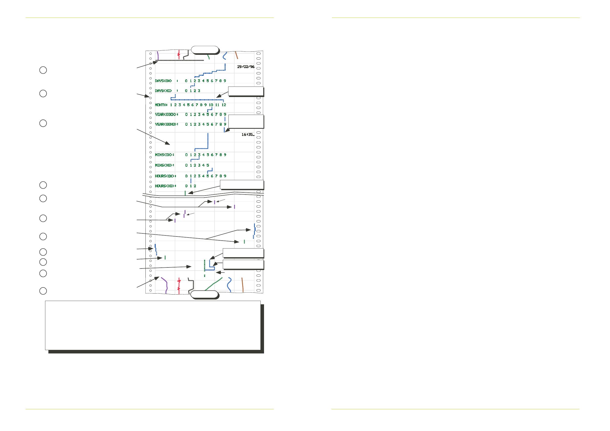
3.3 Multipoint recorder (Cont.)
Notes:
1 RH = Right hand; LH = Left hand
2 Enter = Simultaneous operation of both left and right hand switches for between 1 and 2 seconds then release.
(Operation of both switches for over 4 seconds quits configuration without saving any changes made since
last ‘enter’).
3 Chart speeds: There are five chart speeds, 1 to 5, where 1 = Off. For speed range fitted, see the label
behind the cassette. Table 6.1 shows speeds per range.
4 Alarms (if fitted): Each alarm can be absolute high or absolute low as specified at time of order. See configuration
label (behind cassette) for type fitted.
Start
Enter stops tracing and causes the print head to park at the
centre of the chart (50%).
1
2 4 5
Chart speeds
3
RH key causes ‘Chart Speedset up to be selected for entry
(green pen dots at 50%). Enter key causes pen to indicate
current selection. Use left/right keys to select new chart speed,
then Enter.
RH key causesChart zero’ set up to be selected for entry
(green pen dots at 10% chart width).
1
2
3
RH key causesChart span’ set up to be selected for entry
(green pen dots at 90% chart width). Enter causes the blue
pen to indicate current span. Use left/right keys to adjust,
then Enter.
4
RH key causes ‘Ch 1 Alarm 1’ set up to be selected for entry
(violet pen dots at 20%). Enter causes the violet pen to indicate
current setpoint. Use left/right keys to adjust, then Enter.
5
6
RH key causes next alarm 1 to be selected (not shown).
Continue until all alarm setpoints set up, then Enter.
Alm 1 setpoint
Alm 2 setpoint
After all alarms are set up, and ‘entered’, RH key
causes ‘Time’ to be selected for entry. (Pen dots
at 30%)
Enter causes the 10s of hours select line to be
printed on the chart in green, with the current value
being indicated by the blue pen. LH and/or RH keys
are used to edit.
Enter followed by RH key causes next line to be
printed. Hours units and Minutes 10s and units are
set up in the same way.
When minutes units have been set up, wait until
exact time, then Enter. Time is printed on the chart.
7
9
Date set up is carried out using the same method as
described below for time setting. Final enter causes
date to be printed.
10
Enter causes blue pen to indicate current zero. Use left/right
keys to adjust, then Enter.
8
Operate both keys simultaneously for more than 4
seconds to return to normal recording. End of setup
indicated by black line drawn from 0 to 50%.
11
Finish
Enter then use RH key to
move to next parameter
Use LH/RH keys to
select chart speed
Pen dots at 30% to show
that time is next parameter.
RH key wraps-around
from 12 to 1
Pen dots at 70% to
show that date is next
parameter.
RH key causes ‘Ch1 Alarm 2’ set up to be selected for
entry (violet pen dots at 80%). Enter causes the violet
pen to indicate current setpoint. Use left/right keys to
adjust, then Enter.
Figure 3.3b Simulated chart sample
100mm RECORDERS: CHART / PEN CHANGE INSTRUCTIONS
HA028263
Issue 1 REV 1 August 2011
100mm RECORDERS: CHART / PEN CHANGE INSTRUCTIONS
HA028263
Issue 1 REV 1 August 2011
Page 6 Page 7
3.1 CONTINUOUS TRACE RECORDER WITH NO ANNOTATOR (Cont.)
Figure 3.1 Simulated chart sample
3.2 CONTINUOUS TRACE RECORDER WITH ANNOTATOR
Apart from the fact that the annotator prints only in black, the setting up procedure for continuous-pen
recorders with annotation is the same as that given below for multi-point recorders.
3.3 MULTIPOINT RECORDER
Enter
Finish
Start
Pens 2/3/4
Pen 1
Further ‘Enter’ selects Pen 1 zero setting.
Pens 2, 3 and4 move to 10%; pen 1 to 5%
After further Enter, pen 1 moves to near zero.
Use left & right switches to adjust, then ‘Enter
Further ‘Enter’ selects Pen 2 zero setting,
and so on. When all pens’ zeros and spans
entered, further ‘Enter’ selects channel 1
alarm 1 setting
Enter
Enter
Pen 2
Pens 1/3/4
Final pen
Adjust
Adjust
Pens 2, 3 and 4 move to 20%; pen 1 to 15%.
After further Enter pen 1 moves to current
alarm 1 threshold. Adjust using LH and RH
switches, then Enter.
Further ‘Enter’ selects channel 1 alarm 2
setting. Pens 2, 3 and 4 move to 80%; pen 1
to 85%. After further Enter, pen 1 moves to
current alarm 2 threshold. Adjust using LH
and RH switches, then Enter.
Further Enter selects channel 2 alarm 1
setting, and so on.
pen 1
pen 1
All pens
New threshold
Pen 1
Channel 1 alarm 2
threshold
Channel 2 alarm 1
threshold
Enter
Enter
Enter
Pen 2
Further ‘Enter’ selects Pen 1 span setting.
Pens 2, 3 and 4 move to 90%; pen 1 to 95%
After further Enter pen 1 moves to near
100%. Set span as for zero
Single ‘Enter’ fans pens for changing.
Chart stops
‘Enter’ causes pen 1 to move to 40% , 45%,
50%, 55% or 60% according to current chart
speed (2 in this example). (40% = off).
Use LH or RH switch to select new chart speed
(RH twice to select speed 4 in this example)
Other
pens
Set chart speed
Set pen zeros and spans
Set alarm thresholds
Pen 4
Pe
n
3
P
e
n
1
Onc
w
i
c
After Entering the nal channels alarm 2
threshold, the recorder returns to normal
operations
P
e
n
2
Notes:
1 RH = Right hand; LH = Left hand
2 Enter = Simultaneous operation of both left and right hand switches for between 1 and 2
seconds then release.
(Operation of both switches for over 4 seconds quits configuration without saving any
changes made since last ‘enter’.)
3 Chart speeds: There are five chart speeds, 1 to 5, where 1 = Off. For speed range
fitted, see the label behind the cassette. Table 6.1 shows speeds per range.
4 Alarms (if fitted): Each alarm can be absolute high or absolute low as specified at time
of order. See configuration label (behind cassette) for type fitted.
Enter
Enter
Enter
1
2
4
5
6
7
8
10
11
9
12
Operation of RH switch centres pens
3
Current channel 1
alarm 1 threshold
1 2 3 4 5
Chart speed
Right-hand switch
e
T
e
Adjust
Operating the two switches simultaneously for
between 1 and 2 seconds, causes the
printhead to park at 50% chart width.
Operating the right-hand switch moves to the
next parameter, or operating both switches
together for about 1 second, enters the
parameter’s setup.
Parameters appear in the following order:
Chart speed,
Chart zero,
Chart span,
Alarm setpoints
Time
Date.
Once in setup, the right and left hand keys
are used to adjust the value. Operating both
keys together for 1 to 2 seconds ‘enters’ the
new value.
Figure 3.3b shows the programming
sequence, including changing the time from
15:12 to 16:35, and the date from 12/12/95
to 29/2/96.
Enter
Printhead dots blue at current chart
speed (1 to 5).
Use RH/LH switch to edit
Enter
retnEretnE
Enter
Enter
Enter
Enter
Enter
Enter
Enter
Enter
Enter
Printhead prints year decade and
dots blue at current selection.
Proceed as for time
Enter
Enter
RH switch
Printhead dots green at 50%
RH switch
Printhead dots green at 90%
RH switch
Printhead dots violet at 20%
RH switch
Printhead dots violet at 80%
RH switch
Printhead dots green at 30%
RH switch
Printhead dots green at 10%
RH switch
Printhead dots green at 70%
Enter
Printhead parks
Printhead dots violet at ch1 alarm 1
setpoint. Use RH/LH switch to edit
Printhead dots blue at current zero.
Use RH/LH switch to edit
Printhead dots blue at current span.
Use RH/LH switch to edit
Printhead dots violet at ch1 alarm 2
setpoint. Use RH/LH switch to edit
RH switch
Repeat for channels 2 to 6
alarms 1 and 2. (Printhead
dots in colour of channel)
Printhead prints Units hours and
dots blue at current selection.
Use RH/LH switch to edit.
Repeat for minutes 10s and units
After minutes units, wait for exact
time then Enter. Time printed on
chart
Printhead prints 10’s of hours and
dots blue at current selection.
Use RH/LH switch to edit.
Figure 3.3a Setup sequence
  • Page 1 1
  • Page 2 2
  • Page 3 3
  • Page 4 4
  • Page 5 5
  • Page 6 6

Eurotherm 100mm Recorders Pen/Chart C Operating instructions

Type
Operating instructions
This manual is also suitable for

Ask a question and I''ll find the answer in the document

Finding information in a document is now easier with AI