Page is loading ...

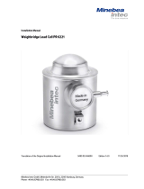
SINGLE POINT BEAM LOAD CELL
LC4001-G120
3-23-14 Higashi-Ikebukuro, Toshima-ku, Tokyo
170-0013 JAPAN
Tel: [81](3)5391-6132 Fax: [81](3)5391-6148
1. SPECIFICATIONS
Rated capacity.........................................................................1.2 N
Rated output ...............................................0.4079mV/V or greater
Maximum safe overload.......................................... 300% OF R.C.
Combined error.....................................................0.015% OF R.O.
Zero balance............................................................±25% OF R.O.
Compensated temperature range...............................-5°C to 35°C
Recommended excitation voltage.................................5 V to 12 V
Maximum excitation voltage.....................................................15 V
Input terminal resistance............................................Approx. 400Ω
Output terminal resistance............................................... 350Ω±5Ω
Insulation resistance...........................500MΩ or greater at 50VDC
Temperature effect on zero...................0.14% OF R.O./10°C Typ.
Temperature effect on span...............0.02% OF LOAD/10°C Typ.
Loading surface dimensions..............................120 mm x 120 mm
Cable length.................................................................FPC 75 mm
2. EXTERNAL VIEW
Unit: mm
3.
REMOVING THE STOPPER FOR TRANSPORTATION
To protect the load cell during transportation, tape and a
stopper are attached to the load cell. Remove them before
use. When removing, use much care not to apply unnecessary
loads (torsion or transverse load) to the load cell.
Caution
The load cell has been installed in a casing with various
pre-adjusted stoppers. Use the load cell as is. Do not
remove the load cell from the casing.
4. SECURING THE LOAD CELL
● Secure the load cell horizontally to a solid surface with
enough rigidity not to bend under normal operating
conditions.
● To secure the load cell, use M4 steel screws with a
screw-in length of 10 mm or less and a tightening torque
of approximately 1N・m.
5.
CONNECTING TO A WEIGHING INDICATOR
● A flexible printed circuit (FPC) is used for the load cell.
Use the provided FPC connector to connect the load cell
to the weighing indicator. When connecting, use much
care to insert the connector in the correct direction.
● The FPC is fragile mechanically and is susceptible to
repetitive bending. When using, secure the connector to
the base.
6. DESIGNING A WEIGHING PLATFORM
● The maximum size for the weighing platform to attach
on the load cell is 120 mm x 120 mm.
● Design the weighing platform to be less than 100 g.
When the weighing platform is less than 100 g, weighing
is possible up to 1.2 N (120 g).
● To attach the weighing platform to the load cell, use an
M3 steel screw with a screw-in length of 8 mm or less
and a tightening torque of approximately 1N・m.
Use much care not to apply unnecessary loads (torsion
or transverse load) to the load cell.
7. PRECAUTIONS ON OVERLOADING
The load cell has been installed in the casing with a
pre-adjusted overload stopper.
However, if a load is applied on corners of the weighing
platform, it may cause the casing to deflect and result in applying
a load exceeding the maximum safe overload of the load cell.
To prevent this overloading, provide corner stoppers.
Attach the corner stoppers so that the stoppers come into
contact with the platform when a load, with approximately
100% of the rated capacity. is applied to each corner of the
platform.
The below illustration shows an example of securing the
connector and providing corner stoppers.
8. MAINTENANCE
● Remove all dirt and dust from the load cell, and always
use the load cell in a clean environment.
● When cleaning, do not wash off the dirt and dust. Use
an air blower.
/