Page is loading ...

CA_
SERIES
OWNER’S GUIDE
For future reference, fill in the information below and
keep this guide in a safe place. Please keep a copy of
your receipt for warranty purposes. This book is for
DEALER NAME ___________________________________________________
ADDRESS ________________________________________________________
TELEPHONE _____________________________________________________
MODEL/CATALOG NUMBER _______________________________________
SERVICE DISCRETE NUMBER _____________________________________
SERIAL NUMBER _________________________________________________
PLEASE KEEP A COPY OF YOUR RECEIPT FOR WARRANTY PURPOSES.
CONTENTS
Page
A FEW WORDS ABOUT YOUR NEW
AIR CONDITIONING UNIT . . . . . . . . . . . . . . . . . . . . . .2
REQUIRED TOOLS. . . . . . . . . . . . . . . . . . . . . . . . . . . . . . . . . .2
INSTALL
ATION. . . . . . . . . . . . . . . . . . . . . . . . . . . . . . . . . .3-11
POWER CORD. . . . . . . . . .. . . . . . . . . . .. . . . . . . . . . . . . .3
WIRING&LOCATION . . . . . . . . . . . . . . . . . . . . . . . . . . . .4
WINDOW INSTALLATION . . . . . . . . . . . . . . . . . . . . . . . .4
STORM WINDOW APPLICATIONS . . . . . . . . . . . . . . . .9
WALL INSTALLATION . . . . . . . . . . . . . . . . . . . . . . . . . . . .9
MASONRY CONSTRUCTION. . . . . . . . . . . . . . . . . . . . 11
OPERATION . . . . . . . . . . . . . . . . . . . . . . . . . . . . . . . . . . . . 11,12
REMOTE CONTROL AND PANEL
CONTROLS . . . . . . . . . . . . . . . . . . . . . . . . . . . . . . . . . . . 11
ENERGY SAVING TIPS . . . . . . . . . . . . . . . . . . . . . . . . . . .12
Pag e
MAINTENANCE . . . . . . . . . . . . . . . . . . . . . . . . . . . . . . . . 12,13
CLEAN FILTER . . . . . . . . . . . . . . . . . . . . . . . . . . . . . . . . . . 12
CLEAN FRONT PANEL . . . . . . . . . . . . . . . . . . . . . . . . . . 13
CARE OF THE REMOTE CONTROL . . . . . . . . . . . . . . 13
REMOTE CONTROL BATTERY
REPLACEMENT . . . . . . . . . . . . . . . . . . . . . . . . . . . . . . . 13
TROUBLESHOOTING . . . . . . . . . . . . . . . . . . . . . . . . . . 13,14
CA1016KR and CA1216KR room air conditioners
Part Number 421 02 9110 00 - Printed 02/08
P1_Owners Guide - 10K,12K.pdf 30/01/2008 1:51:12 PM

CA_
SERIES
2
A FEW WORDS
ABOUT YOUR NEW
AIR CONDITIONING UNIT
Thank you for choosing a Climette room air conditioner
to cool your home or office. In addition to providing
economical cooling comfort, Climette room air condi-
tioners filter and dehumidify the air in the room.
This owner’s guide will supply all the information you
need to install, operate, and maintain your new air
conditioning unit. Please read the entire manual
before installing the unit. See Fig. 1 for a part identifi-
cation and description of the unit.
REQUIRED TOOLS
• Phillips and flathead screwdrivers
• pencil
• level
• measuring tape
• drill
•
1
/
8
-in. drill bit
• scissors
S
W
I
N
G
O
F
F
O
N
/
M
O
D
E
T
I
M
E
R
F
A
N
S
P
EE
D
F
H
R
REMOTE
CONTROLLER
INTERIOR
AIR INLET
GRILLE
CONTROL PANEL EXHAUST AIR
VENT LEVER
POWER CORD
EXTERIOR
AIR INLET
AIR OUTLET
AIR FILTER
CABINET
FRONT PANEL
FIGURE 1 — AIR CONDITIONER

INSTALLATION
INSTALLATION INSTRUCTIONS
Electrical Requirements
A Reset Button B Test Button
This room air conditioner is equipped with a power supply cord required
by UL. This power supply cord contains state-of-the-art electronics that
sense leakage current. If the cord is crushed, the electronics detect leakage
current and power will be disconnected in a fraction of a second.
r
To test your power supply cord:
1. Plug power supply cord into a grounded 3-prong outlet.
2. Press RESET.
3. Press TEST (listen for click; Reset button will trip and pop out).
4. Press and release RESET (listen for click; Reset button will latch
and remain in).The power supply cord is ready for operation.
NOTES:
• The Reset button must be pushed in for proper operation.
• The power supply cord must be replaced if it fails to trip when the
test button is pressed or fails to rest.
• Do not use the power supply cord as as an off/on switch. The
power supply cord is designed as a protective device.
• A damaged power supply cord must be replaced with a new power
supply cord obtained from the product manufacturer and must not
be repaired.
• The power supply cord contains no use serviceable parts. Opening
the tamper-resistant case voids all warranty and performance claims.
3
• Remove and properly dispose of packaging materials.
Remove tape and glue residue from surfaces before
turning on the air conditioner. Rub a small amount
of liquid dish soap over the adhesive with your fingers.
Wipe with warm water and dry.
• Do not use sharp instruments, rubbing alcohol,
flammable fluids, or abrasive cleaners to remove
tape or glue. These products can damage the
surface of your air conditioner.
• Handle air conditioner with care.
ELE CTR IC SHO CK HAZ ARD
• Plug into a grounded 3-prong outlet.
• Do not remove ground prong.
• Do not use an adapter.
• Do not use an extension cord.
• Failure to follow these instructions can
result in death, fire, or electrical shock.
Power Supply Cord
NOTE: Your unit’s device may differ from the one shown.
Unpack the Air Conditioner
EXC ESS IVE WE IGH T H AZA RD
Use two or more people to move and
install air conditioner.
Failure to do so can result in back or
other injury.
Remove packaging materials
• The portable air conditioner should be connected
to a 115 V, 60 Hz, 15- or 20-amp fused 3-prong
grounded outlet.
• The use of a time-delay fuse or time-delay circuit
breaker is recommended.
• All wiring must comply with local and national
electrical codes and be installed by a qualified
electrician. If you have any questions, contact
a qualified electrician.
P3_Owners Guide - 10K,12K.pdf 30/01/2008 1:55:55 PM

Your Climette room air conditioner was designed to be
installed in a single or double hung window. This air
conditioner is not designed for use with vertical (slider
type) windows.
WIRING
The air conditioner is powered by plugging it into a
compatible wall outlet. The electrical outlet MUST
match the plug on the unit power cord. See Table 1 for
receptacle types and fuses. The unit nameplate con-
tains unit electrical data, unit ratings, and identifica-
tion numbers. The unit nameplate is located on the
right side of the unit. Do not use a plug adapter or an
extension cord.
Check available power supply and resolve any wiring
problems before installing and operating the air condi-
tioner. If wiring is required, all wiring must comply
with all local and national electrical codes. All wiring
must be installed by a qualified electrician. If you have
any questions regarding the unit electrical data or wir-
ing, consult a qualified electrician before installation.
For your safety, this air conditioner is grounded
through the power cord plug when plugged into a
matching wall outlet. The power cord is 60-in. long.
TABLE 1 — RECEPTACLE TYPE AND FUSES
LOCATION
The room air conditioner is designed to fit easily into a
single or double hung window. However, since window
designs vary, it may be necessary to make some modi-
fications for safe and proper installation.
Make sure the window and frame are structurally
sound and free from dry or rotted wood. Replace wood
if necessary or relocate.
For maximum efficiency, install the air conditioner on
the side of the house or building that has more shade
than sunlight.
Provide sufficient clearance for the air conditioner to
allow proper air circulation through and around the
unit. The rear of the unit must be outdoors (not in a
garage or inside of the building). Provide 20-in. of
clearance on each side of the unit. Provide 20-in. of
clearance from the rear of the unit to any obstruction.
Provide 12-in. of clearance from the top of the unit. See
Fig. 2.
Unit should be at least 30-in. above the floor and out-
side ground.
Curtains and other objects should be moved if they
block indoor airflow.
Unit must be within reach of a proper electrical wall
outlet. Do not use an extension cord.
The unit was designed to evaporate condensation
under normal conditions. Under extreme humidity
conditions, excess condensation may cause the
basepan to overflow to the outside of the unit. The unit
should be installed where condensation drip cannot
cause damage.
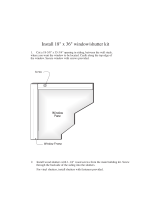
WINDOW INSTALLATION
To install the room air conditioner in a window, per-
form the following procedure.
1. Check contents of installation hardware package
provided with air conditioner. See Table 2. Make
sure all the items are provided.
2. Determine which window will be used for installa-
tion. See Location section on this page.
3. Check that the window opening dimensions are
suitable for installation. Fo r CA1216KR units, the
window must be from 24 to 38-in. wide and the
window must open at least 15-in. high. For
CA1216KR units, the window must be from 27 to
41-in. wide and the window must open at least
16-in. high. It is recommended that the window
sill be at least
5
/
8
-in. thick to support the weight
of the air conditioner. See Table 3 for unit
dimensions.
Electrical shock can cause injury or death. Do not
install unit or remove front grille with the power
cord plugged in. Be sure unit is unplugged before
performing any installation or maintenance.
RECEPTACLE TYPE AND FUSES
VOLTS INDICATED/Hz 125/60
AMPS 15
WALL OUTLET
FUSE SIZE 15
TIME DELAY FUSE
(Circuit Breaker)
Plug Type
AWNING
SIDE
OBSTRUCTION
GROUND
FENCE,
WALL, OR
OTHER
OBSTACLE.
12" MIN.
30" MIN.
20"
MIN.
20"
MIN.
FIGURE 2 — AIR CONDITIONER CLEARANCES
CA_
SERIES
4
P4_Owners Guide - 10K,12K.pdf 30/01/2008 1:58:57 PM

5
TABLE 2 —INSTALLATION HARDWARE PACKAGE TABLE 3 —AIR CONDITIONER
CABINET DIMENSIONS
4. For storm windows, open or remove the outer win-
dow before installing the air conditioner. Remove
any screens that are in the window.
5. Remove the front panel of the air conditioner by
removing the side panel screws (one on each side)
and pulling the front panel off the air conditioner
chassis. Save the screws for reinstallation. See
Fig. 3.
6. Remove the chassis security screws from the sides
of the cabinet. Save screws. See Fig. 3. A pull han-
dle is provided for chassis removal. Gently slide
the chassis from the cabinet by pulling on the han-
dle. The chassis is heavy and assistance may be
required. Take care not to bend or damage the coil
fins on the chassis. See Fig. 4.
7. Cut sealing strip (provided) to match length of top
channel. Save remaining seal strip for use in
Steps 14 and 22. Peel and stick one side of the
sealing strip on to the top channel (provided) as
shown in Fig. 5. Use
1
/
4
-in. screws (provided) to
attach top channel to cabinet. Top channel may
require 4 or 5 screws depending on model. See
Fig.6.
8. Attached the bottom channel (provided) to the bot-
tom of the cabinet. Use four
1
/
4
-in. screws (pro-
vided). Screws are installed from the inside of the
cabinet to the outside to attach the bottom chan-
nel. See Fig. 6.
9. Install the side shutters (provided). The side shut-
ters are identified as right and left on each frame.
Slide the top and bottom shutter frames into the
top and bottom channels on the cabinet. Attach
the shutters to the cabinet using four
1
/
4
-in.
screws (provided). See Fig. 7.
10. Attach the mounting brackets (provided) to the
angle brackets (provided) using two 1
1
/
2
-in. bolts,
lock washers, and nuts (provided). Two bolts are
used on each bracket assembly. See Fig. 8. Do not
tighten the bolts immediately. It may be necessary
to adjust the depth of the bracket assembly
depending on the window sill. Install the 2 level-
ing screws (provided) onto the bracket assemblies.
See Fig. 8.
YTQMETI
3
/
4
-in. Screws 10
1
/
4
-in. Screws 23
Top Channel 1
Bottom
Channel
1
Lock Washers 4
1
1
/
2
-in. X
1
/
4
-in.
Bolts
4
1
/
4
-in. Nuts 4
Mounting
Brackets
2
Angle
Brackets
2
Shutter
Clamps
2
Left and Right
Side Shutters
1
Sealing Strip 1
Foam 1
End Cap and
Leveling Screw
2
UNIT WIDTH (in.) LENGTH (in.) HEIGHT (in.)
CA1016KR 20.5 23.1 14.8
CA1216KR 22.8 28.0 15.7
P5_Owners Guide - 10K,12K.pdf 30/01/2008 2:00:16 PM

11. Test the bracket assembly in the window. See
Fig. 9. Adjust the location of the angle brackets if
necessary. If location of angle brackets is correct
for installation, tighten bolts on assembly. Level-
ing screws should touch the outside wall. If level-
ing screws are too far away from wall, it may be
necessary to shim the area with a solid piece of
wood. See Fig. 10.
12. Measure the width of the inside sill of the window
and mark the center of the sill. The V-slot on the
brackets should be placed 9
5
/
8
-in. from center on
both sides for CA1016KR units. The V-slot on the
brackets should be placed 10
5
/
16
-in. from center
on both sides for CA1216KR uni ts. See Fig. 11.
Mount the 2 bracket assemblies on the window
sill with a
3
/
4
-in. screw (provided). The holes on
the bracket assemblies must line up with holes in
the bottom of the cabinet for installation.
13. Place a carpenter’s level on the bracket assembly.
Turn the leveling screw on the bracket assembly
until the bracket is slightly tilted down. A slight
pitch will be needed for condensate run off. The
maximum pitch angle should not exceed
3
/
16
inch. See Fig. 9.
14. Cut remaining sealing strip (provided) piece to fit
across the bottom of the window sash. See Fig. 12.
After the sealing strip has been cut, remove the
peel-off backing and stick to bottom of window.
Remaining seal strip material is used in Step 22.
15. Center the cabinet in the window. Lower the win-
dow sash until it rests firmly in the upper channel
installed in Step 7. Make sure the top and bottom
of the cabinet fits snugly to the window opening.
Make sure the bottom channel fits into the groove
in the bracket assemblies. See Fig. 13.
16. Secure the cabinet to the brackets using three
1
/
4
-in. screws (provided) for each bracket. Check to
make sure cabinet is angled slightly downward.
Adjust leveling screws if necessary. See Fig. 14.
17. Pull out the expanding side shutters from the
sides of the cabinet. The panels should expand to
cover the entire width of the window. There is a
hole provided in the top end of each side shutter
which is used to secure the panels to the window.
A shutter clamp is also provided to secure the bot-
tom of the shutter to the window sill. With the
wing panels expanded, mark the drilling locations
on the sides of the window frame and sill (through
the holes in the panels).
18. Drill the holes marked in Step 16 with
1
/
8
-in. drill
bit. With the wing panels expanded, secure the
wing panels with two
3
/
4
-in. screws and shutter
clamp provided (each side). See Fig. 15.
Cabinet is not secure and may fall out of window. Be
careful with air conditioner until it is secured to the
window.
SIDE PANEL SCREW (EACH SIDE)
CHASSIS SECURITY
SCREW HIDDEN
CHASSIS SECURITY
SCREW (EACH SIDE)
SIDE PANEL
SCREW (HIDDEN)
COIL
PULL HANDLE
CHASSIS
Fig. 2
SEALING
STRIP
" L" SHAPED
TOP CHANNEL
FIGURE 3 — FRONT PANEL REMOVAL
FIGURE 4 — CHASSIS REMOVAL
FIGURE 5 — TOP CHANNEL LOCATION
CA_
SERIES
6
P6_Owners Guide - 10K,12K.pdf 30/01/2008 2:02:25 PM

7
1/4" SCREW
CHANNEL
"U" SHAPED CHANNEL
POSITION
SHUTTER FRAME
RIGHT
SHUTTER
1/4" SCREW
V-SLOT
BRACKET ASSEMBLY
BRACKET BOLTS
LEVELING SCREW
(TOP VIEW)
(SIDE VIEW)
90 ANGLE
SUPPORT
BRACKETS
(2) 3/4" SCREWS PER BRACKET
OUTER WALL CONSTRUCTION
LEVELING SCREW
BRACKET ASSEMBLY
3/16" MAXIMUM
SOLID PIECE WOOD
(IF REQUIRED)
9 5/8"
CENTER
WINDOW SILL
V-SLOT
CA1016KR = 9 5/8"
CA1216KR = 10 5/16"
9 5/8"
10 5/16"
10 5/16"
WINDOW
SASH
WINDOW SASH
SEALING STRIP
FOAM STRIP
WINDOW SASH
"L"SHAPED
MOUNTING
CHANNEL
FIGURE 6 — TOP AND BOTTOM
CHANNEL INSTALLATION
FIGURE 7 — SIDE SHUTTER INSTALLATION
FIGURE 8 — BRACKET ASSEMBLY
FIGURE 9 — BRACKET LOCATION
AND INSTALLATION
FIGURE 10 — FIELD-SUPPLIED WOOD SHIM
FIGURE 11 — BRACKET LOCATION
ON WINDOW SILL
FIGURE 12 — SEALING STRIP ON
BOTTOM OF WINDOW SASH
FIGURE 13 — CABINET LOCATION

19. Slide chassis into cabinet. Be careful not to pinch
or cut your fingers when you are reinstalling the
chassis. Get assistance if necessary. Secure cabi-
net to chassis by installing chassis screws
removed in Step 6.
20. Reinstall the front panel. Make sure all lock tabs
are engaged. Secure front panel to cabinet with
the screws saved from Step 5. Make sure that the
power cord comes out of the unit.
21. Cut foam (provided) to fit the length of the win-
dow. Insert the foam between the top of the lower
window sash and the window panes of the upper
window. See Fig. 16. Make sure there is a firm fit
to prevent air leakage between the windows. This
also prevents insects from entering through the
window.
22. Some installations may require additional sealing
around the window or air conditioner. Additional
sealing strip material is provided if needed.
23. The unit was designed to evaporate condensation
under normal conditions. Under extreme humid-
ity conditions, excess condensation may cause the
basepan to overflow to the outside of the unit. A
field-supplied drain hose may be installed at the
drain plug if required to route condensate away
from the unit. See Fig. 17.
24. Plug in the unit.
STORM WINDOW APPLICATIONS
If the window is blocked by a storm window and the
storm window cannot be removed, a mounting board
(field provided) will need to be added to the window
sash. The air conditioner needs to be pitched down-
ward to the back in order for condensate to drain prop-
erly. The frame of the storm window (or any other
obstruction) must be at least
1
/
2
-in. lower than the
window sill. If the storm window frame is not at least
1
/
2
-in. below the window sill, then a mounting board
will need to be added to raise the height of the window
sill. See Fig. 18. The board will need to be provided
and cut by the installer.
1. The wood mounting board should be a minimum
of 1
1
/
2
-in. wide and should run the length of the
window. The thickness of the mounting board is
dependent on the height of the storm window
frame. The mounting board should raise the front
of the air conditioner high enough so that the unit
will be pitched downward at least
5
/
8
-in. when the
back of the unit is resting on the storm window
frame. See Fig. 18.
2. Cut the wood mounting board to fit the window.
3. Install the wood mounting board on the window
using 2 field-provided nails or screws.
4. Drain holes or slots in storm window frame must
not be caulked or painted shut. Holes are needed
to drain rain water and condensate. Ensure that
trapped water can drain out.
1/4"
SCREWS
COIL
3/4" SCREWS
SECURITY SCREW
SHUTTER
CLAMP
SHUTTER CLAMP
FIGURE 14 — CABINET INSTALLATION
FIGURE 15 — SIDE SHUTTER INSTALLATION
FOAM
SEAL
DRAIN HOSE
(NOT INCLUDED)
FIGURE 16 — SASH FOAM LOCATION
FIGURE 17 — FIELD-SUPPLIED DRAIN HOSE
CA_
SERIES
8

9
WALL INSTALLATION
To install the room air conditioner in the wall, perform
the following procedure:
1. Remove air conditioner from shipping box. Do not
install window installation parts.
2. Determine the location for air conditioner. Make
sure there is adequate clearance on the inside and
outside of the wall. Ensure that the power cord
will reach the available socket without an exten-
sion cord. Air conditioner can be installed in walls
up to 7 in. thick. Side louvers must never be
blocked. Select a wall surface that:
•does not support major structural loads such as
the frame construction at ends of windows and
under truss-bearing points
•does not have plumbing or wiring routed inside
•is near existing electric al outlets or near where
a new outlet can be installed
•faces the area to be cooled and is not blocked by
obstructions
•allows unblocked airflow from rear (outside) of
installed air conditioner
3. The following parts will need to be provided by the
installer:
•wood frame
•wood shims
•wood screws (no. 10, 1-in. long)
4. Working from the inside of the room, find a wall
stud nearest the center of the area where the air
conditioner will be installed. This can be deter-
mined by sounding walls or using a stud finder.
5. Cut or knock out a hole on each side of the center
stud. See Fig. 19.
6. Measure between the inside edges of every other
stud as shown in Fig. 19.
7. Follow all local building codes when building and
installing frame. Build a wooden frame that will
be placed around the unit in the wall. The frame
will reinforce the hole in the wall where the air
conditioner is installed and is used to secure the
air conditioner to the wall. The frame should have
an inner dimension of 20.5-in. width by 14.8-in.
height for CA1016KR air conditioners or 22.8-in.
width by 15.7-in. height for CA1216KR air condi-
tioners to ensure that the air conditioner will fit
inside the frame. See Fig. 20. The depth of the
frame should approximately match the depth of
the wall. The thickness of the frame will need to
be added to the dimensions to determine the size
of the hole in the wall.
For example, if using
3
/
4
-in. thick wood for the
frame, the hole would need to be:
20
1
/
2
+
3
/
4
+
3
/
4
= 22-in. wide.
8. After the frame has been constructed, check to
make sure that the air conditioner fits correctly
inside it. If the frame is too tight or too loose,
adjust the size or re-construct.
9. Measure the outer dimensions of the frame and
use those dimensions to cut the hole in the wall.
Make sure the hole is level or condensate will not
drain properly.
10. Install wooden frame into hole in wall. Make sure
frame is properly secured. Fill in the space
between the frame and the studs with wood shims
(spacers). Nails spacers to studs. If required, pro-
vide studs around entire frame to reinforce stabil-
ity of wall. See Fig. 21.
IMPORTANT: Read entire instructions before cut-
ting hole in wall.
IMPORTANT: Be sure to measure air conditioner
to check size before constructing frame.
IMPORTANT: If thickness of the wall covers top
and side vents of the air conditioner when it is
installed, the outer portion of the wall opening
must be widened. The top and side vents must be
clear and uncovered.
FIGURE 18 — STORM WINDOW APPLICATIONS
FIGURE 19 — WALL INSTALLATION
LOCATION
P9_Owners Guide - 10K,12K.pdf 30/01/2008 2:15:16 PM

11. Caulk joints in wood frame as required. If wall
thickness is 7-in. or more, add aluminum flashing
over bottom of frame opening to ensure no water
can enter area between inner and outer wall.
12. Remove the chassis from the unit cabinet.
13. Slide the empty cabinet into the wall opening and
into wooden frame. Approximately 2
1
/
2
in. of the
cabinet should be in the room. The rest of the cab-
inet should be positioned through and outside the
wall. See Fig. 22. Maintain proper slope for con-
densate drain operation. Bottom rail should be
resting firmly on bottom board of wooden frame.
14. Secure bottom rail to wood frame with two large
wood screws (1-in. long) using the two holes in the
bottom of the channel. See Fig. 23.
15. There are screw holes in the cabinet (4 each side,
4 top) which are used to secure the cabinet to the
wooden frame. With the cabinet in its final posi-
tion, drill holes in the wooden frame using the
screw holes in the cabinet as a guide. After the
holes have been drilled, secure the cabinet to the
wooden frame using field-supplied screws. See
Fig. 24.
16. Caulk around wood frame and wall opening on
outside wall for a water-tight seal.
17. Optional caulking between the cabinet and the
wooden frame may be done on inside wall. Caulk-
ing provides an air seal around the cabinet. Deco-
rative wood trim may be added to provide a more
pleasing appearance.
18. Lift chassis and carefully slide it into the cabinet.
Be sure that it is firmly seated towards the rear of
the cabinet.
19. Install the front panel.
20. Plug in the unit.
Be careful when handling chassis. Sharp edges on
coil fins can cause personal injury.
Do not push on the controls or the coil when install-
ing chassis. Damage to unit or personal injury could
result.
FIGURE 20 — FRAME CONSTRUCTION
UNIT
CA_
DIMENSIONS (in.)
A B
1016KR 14.8 20.5
1216KR 15.7 22.8
FIGURE 21 — FRAME INSTALLATION
FIGURE 22 — CABINET LOCATION
IN WALL
CA_
SERIES
10

11
MASONRY CONSTRUCTION
The air conditioner is installed the same way as the
Wall Installation section with a few exceptions. Follow
all local and national building codes.
The cabinet can be secured to the masonry by using
masonry nail or masonry anchor screws.
Another installation technique would be to construct a
frame of 2 x 4s and install the frame between the wall
opening and the cabinet. The frame must be securely
anchored to the masonry wall opening.
Use a lintel to support masonry above wall opening.
Install exterior cabinet support brackets.
OPERATION
An electronic-type control is used on your Climette air
conditioner.
The electronic control consists of a control panel and a
remote control. Both the control panel or the remote
control can be used to set cooling and fan modes and
adjust the desired temperature. See Fig. 25. Other
additional features are provided.
REMOTE CONTROL AND
PANEL CONTROLS
Either the remote control or the control panel on the
air conditioner can be used. The battery of the remote
control will need to be installed before it can be used.
■ TURN UNIT OFF/ON — Press the ON/OFF button
on the remote control or control panel.
NOTE: To switch from Celsius to Fahrenheit, press the
UP ARROW and DOWN ARROW buttons on the con-
trol panel (not the remote control) at the same time.
■ COOLING MODES — The air conditioner can be
set to three different cooling modes — Cooling, Fan
Only, or Energy Saving. Press the MODE button to
select the cooling mode.
In Cooling mode, the air conditioner will run and pro-
vide cooling. The amount of cooling can be adjusted
with the FAN SPEED button. If the fan speed is set to
Auto mode, the fan speed adjusts automatically from
low to high based on the setting of the thermostat and
the actual room temperature.
In Fan Only mode, the fan operates to circulate the air
in the room, but there is no cooling operation. This
mode is used to circulate the air in the room when
cooling is not required. The amount of circulation can
be adjusted with the FAN SPEED button. Auto cannot
be selected in Fan Only mode.
In Energy Saving mode, the air conditioner will auto-
matically switch from cooling to fan only mode when
cooling is not required. Fan speed can be selected
in Energy Saving mode. When the room temperature
is 2 degrees higher than the thermostat setting, the air
conditioner will run in cooling mode. When the room
temperature is lower than 66 F, the unit will turn off
(no cooling or fan). At all other times, cooling will be off
and the fan will run on Low speed.
■ FAN SPEED — The air conditioner Fan mode can be
set to High, Medium, Low, or Auto. Press the FAN
SPEED button to select the fan speed.
High fan mode is recommended for very warm days or
when a fast initial cooling of the room is desired.
Medium fan mode is recommended on moderately warm
days or when the unit has been operating for some time
and the temperature is about to reach its desired set-
ting. Low fan mode is recommended on slightly warm
days or after the room temperature has reached its
desired setting. Auto mode adjusts the fan speed auto-
matically from low to high based on the setting of the
thermostat and the actual room temperature.
■ THERMOSTAT — The temperature setting on the
thermostat can be adjusted from a range of 66 to 88 F
(19 to 31 C). The air conditioner will start and stop
cooling operation in order to maintain the temperature
setting of the thermostat.
Press the Down Arrow button to lower the tempera-
ture setting. Press the Up Arrow button to raise the
temperature setting.
FIGURE 23 — SECURING BOTTOM RAIL OF
CABINET
FIGURE 24 — SECURING CABINET
TO FRAME

■ TIMER MODE — Your Climette Air Conditioner unit
can be programmed so that the unit will shut off after
a certain number of hours (if operating) or turn on
after a certain number of hours (if off).
Press the Timer button to start the Timer mode. The
number of hours will start at 0. The range is 0 to
24 hours.
If the unit is operating, the number of hours until the
unit will turn off will be displayed. If the unit is off, the
number of hours until the unit will turn on will be dis-
played. Use the UP and DOWN ARROW buttons to
change the number of hours.
Press the Timer button again to cancel Timer mode.
■ SWING BUTTON — The Swing button is used to
start or stop the vertical air vanes from swinging back
and forth.
■ EXHAUST AIR VENT LEVER — When the lever is
pushed down, the unit will circulate room air. When
the lever is pushed up, some of the room air is
exhausted to the outside.
ENERGY SAVING TIPS
Your Climette air conditioner is designed to operate effi-
ciently and save on energy costs. Follow these recom-
mendations for even greater energy savings.
• Select the warmest thermostat setting that will suit
your comfort needs and leave the thermostat at that
setting.
• Keep the air filter clean (clean approximately every
30 days).
• Use drapes, curtains, or shades to keep direct sun-
light from heating the room.
• Do not obstruct the front panel air intake. Do not
obstruct the top air discharge. Allow air to circulate
freely around the air conditioner.
• Start your air conditioner before outdoor tempera-
ture, cooking heat, or groups of people make the
room hot and uncomfortable. This avoids an initial
period of discomfort while the air conditioner is cool-
ing the room.
• When outdoor temperature is cool enough, use the
FAN ONLY setting. This circulates indoor air, pro-
vides comfort, and utilizes less electricity than
when operating in cooling modes.
MAINTENANCE
When servicing the air conditioner, make sure the
mode is set to OFF and the unit is unplugged from the
electrical outlet.
CLEAN FILTER
Normally, the air filter should be cleaned every
30 days. The filter is highly efficient in removing
airborne particles. More frequent cleaning may be
required in areas with low outdoor and indoor air
quality.
F
HR
INDICATION SYMBOLS OF LED ON CONTROL PANEL:
HIGH FAN SPEED
MEDIUM FAN SPEED
LOW FAN SPEED
AUTO FAN SPEEDCOOLING
FAN ONLY
DISPLAY SET TEMP
DISPLAY SET TIMER
TIMER
Above LED lights on when the relevant mode is in used.
ENERGY-SAVING
FIGURE 25 — CONTROL PANEL AND REMOTE CONTROL
CONTROL PANEL
REMOTE CONTROLLER
CA_
SERIES
12
SWIN
G
N
O
F
F
O
/
MODE
TIME
R
F
A
N
SPEE
D
F
H
R
F
Power
Mode
+
_
Temp/Time
Auto
Power Saver
Mid
High Low
Timer
Fan Spee d
Swing

13
To remove the filter, grasp the filter handle tabs on the
right center of the front inlet grille and slide the filter
out to the right. The filter may be vacuumed or washed
by hand in warm water. Use of a mild detergent is rec-
ommended. Dry the filter thoroughly after washing.
Replace the air filter by sliding it back into the filter
slot. Do not operate unit without filter in place.
CLEAN FRONT PANEL
The front panel may be cleaned after it is removed
from the air conditioner. Wash the panel by hand with
warm water and a mild soap. Be sure to thoroughly
dry the panel before reinstalling. Never pour water
directly on the unit. Do not use gasoline, thinner, or
other chemicals to clean unit.
CARE OF THE REMOTE CONTROL
The remote control should last indefinitely with proper
care. Do not expose the remote control to direct heat.
Do not spill liquids or place heavy objects on the
remote control. Make sure the signal from the remote
control to the air conditioner is unobstructed.
TROUBLESHOOTING
NOTE: If circuit breaker is tripped repeatedly, or fuse is blown more than once, contact a qualified electrician.
See Fig. 26 for wiring diagram.
NOITULOSESUACMELBORP
UNIT DOES NOT START Unit may have become unplugged. Check that unit is securely plugged into the wall
socket.
.etoN eeS .esuf ecalpeR.nwolb evah yam esuF
Circuit breaker may have tripped. Reset circuit breaker. See Note.
Unit mode may be set to OFF. Check to make sure Cooling mode is selected.
UNIT NOT PROVIDING ENOUGH
COOLING
eb yam taht erutinruf ro ,sdnilb ,sniatruc yna evomeR.dekcolb si wolfria tinU
blocking indoor airflow. Check outdoor airflow and
remove any blockage to outdoor airflow.
Thermostat temperature setting is too high. Reset thermostat to a lower (cooler) temperature.
.retlif ria naelc dna evomeR.ytrid si retlif ria tinU
Room was excessively hot when cooling oper-
ation started.
Allow sufficient time for unit to cool room.
Compressor Overload tripped. Let fan run for approximately 10 minutes to reset
compressor overload and restart compressor.
UNIT MAKING NOISES bbub ,gnikcilc woL.noitarepo lamroN ling, or whooshing noises are nor-
mal during operation of the unit.
.strap esool nethgiT.strap esooL
.tinu ot troppus lanoitidda edivorP.troppus etauqedanI
UNIT ODORS Formation of mold, mildew, or algae on wet
surfaces.
Remove drain plug and drain condensate from unit.
Clean base pan.
WATER DRIPPING OUTSIDE rehtaew dimuh dna toh gnirud ffonur noitasnednoC.noitarepo lamroN
is normal. A field-supplied drain hose can be
installed if required.
WATER DRIPPING INSIDE Unit is not installed at proper angle. Unit must be tilted slightly outside for proper runoff of
condensation. Check that installation is correct and
make necessary adjustments.
ICE OR FROST BUILD-UP ON COIL .retlif ria naelc dna evomeR.ytrid si retlif ria tinU
ria roodtuo nehW.erutarepmet edistuo woL is approximately 65 F (18 C) or
below, frost may form when unit is in Cooling mode.
Switch unit to Fan Only mode until ice or frost melts.

CA_
SERIES
14
LEGEND
F
I
G
URE 2
6 — SC
H
EMA
TI
C
D
IA
GR
A
M; M
OD
ELS CA1016KR AND CA1216KR
CN —
Connection
RY — Relay
P14_Owners Guide - 10K,12K.pdf 30/01/2008 2:32:11 PM

International Comfort Products, LLC
Room Air Conditioner Limited Warranty
Subject to the conditions and exclusions listed below International Comfort Products LLC (hereinafter referred to as “ ICP”)
warrants this product against failures due to defects in materials and workmanship.
TWO YEAR WARRANTY - ICP warrants to the initial purchaser of this product against failures due to defects in materials or
workmanship under normal use and maintenance for a period of two years from the date of original purchase. ICP, through its
authorized independent servicing dealers or distributors, will either repair or replace a defective product (as decided solely by
ICP) free of charge to the user. ICP may replace any defective part with either a new or remanufactured part, at ICP’s sole option.
THIS LIMITED WARRANTY DOES NOT INCLUDE costs incurred for diagnosing, removing, installing, shipping or transporting
the product or any parts. User is responsible for these costs
LIMITATION OF WARRANTIES — ALL IMPLIED WARRANTIES AND CONDITIONS (INCLUDING IMPLIED WARRANTIES AND
CONDTIONS OF MERCHANTABILITY AND FITNESS FOR A PARTICULAR PURPOSE) ARE HEREBY LIMITED IN DURATION TO
THE PERIOD FOR WHICH THE APPLICABLE PRODUCT COMPONENT IS EXPRESSLY WARRANTED HEREIN. Some states or
provinces do not allow limitations on how long an implied warranty lasts, so the above limitation may not apply to you.
THE EXPRESS WARRANTIES MADE IN THIS WARRANTY ARE EXCLUSIVE AND MAY NOT BE ALTERED, ENLARGED OR
CHANGED BY ANY DISTRIBUTOR, DEALER, OR OTHER PERSON WHATSOEVER. ICP WILL NOT BE RESPONSIBLE FOR
ANY SPECIAL, INCIDENTAL OR CONSEQUENTIAL PROPERTY OR COMMERCIAL DAMAGES OF ANY NATURE WHATSOEVER.
Some states or provinces do not allow the exclusion of incidental or consequential damages, so the above limitation may not
apply to you. All work provided for by this warranty shall be performed during normal working hours. All replacement parts,
whether new or remanufactured, assume as their warranty period only the remaining time period for which the replaced
component is expressly warranted herein.
ICP WILL NOT BE RESPONSIBLE FOR:
1. Damage or failure due to failure to perform normal maintenance outlined in the Owner’s Guide.
2. Instruction on methods of control and use of air conditioning unit after initial installation.
3. Damage or repairs needed as a consequence of faulty installation or application. This is the responsibility of the installer.
4. Failure to start due to voltage conditions, blown fuses, open circuit breakers, or any other damages due to the inadequacy
or interruption of electrical service.
5. Damage or repairs needed as a consequence of any misapplication, abuse, unauthorized alteration, improper servicing or
operation.
6. Damage as a result of floods, winds, fires, lightning, accidents, corrosive environments, or other conditions beyond the
control of ICP.
7. Any parts not supplied or designated by ICP.
8. ICP products installed outside the continental U.S.A., Alaska, Hawaii, and Canada.
9. Shipping damage or damage as a result of storing or transporting the unit.
This warranty gives you specific rights, and you may also have other rights which vary from state to state or province to province.
IF YOUR UNIT DOES NOT WORK, FOLLOW THESE STEPS IN ORDER:
1. Check the things you can do yourself. These include being sure the air conditioner is plugged in an appropriate receptacle,
checking the fuse or circuit breaker and ensuring its replacement or resetting, if necessary, and rereading the instruction
book to ensure all controls are set properly. By doing this you can save money. Many unnecessary calls result in the
serviceman doing what the owner can do for himself.
2. CONTACT YOUR DEALER. You may find this name printed on the product, on your invoice, or in your Homeowner’s Packet.
3. CONTACT ICP IF A SATISFACTORY SOLUTION IS NOT REACHED IN STEP 2.
International Comfort Products LLC, 650 Heil Quaker Blvd, P.O Box 128, Lewisburg Tennessee, USA, 37091
Telephone (931) 270-4110
FOR FUTURE REFERENCE, FILL IN DETAILS OF YOUR PURCHASE. KEEP YOUR SALES RECEIPT.
Model/Catalog No. _____________________ Installed By: ___________________________________________________________
Service/Discrete No. ____________________ Name of Owner ________________________________________________________
Unit Serial No. _________________________ Address of Installation __________________________________________________
Date of Installation _____________________ ______________________________________________________________________
6060 Burnside Court, Unit 1
Mississauga, ON L5T 2T5
www.climette.ca
©2008 International Comfort Products, LLC
A member of the United Technologies Corporation family.
Stock symbol UTX.
P15_Owners Guide - 10K,12K.pdf 30/01/2008 2:56:06 PM
/