Page is loading ...

Bedienungsanleitung
Countryman GPS plus

07DEUTSCH
Signalkabel (7 m)
Koaxialkabel (1,5 m)
Fernseher
3. Anschluss der Komponenten
Mobile Benutzung
Befestigen Sie die 4 Auflagen unter die Basis-Pads.
7
ENGLISH GERMAN FRENCH SPANISH DUTCH
3. Operating Instruction
3-1. Connection Diagram
Use the black color controller cable to connect between the controller and
antenna.
The controller cable looks similar to the antenna cable but you can distinguish
them by the color and labeling.
Portable use
Attach 4 Base Pads to the bottom plate
Adaptor or Cigarette light adaptor
Receiver cable
(Grey color)
Controller cable
Controller
Controller
(Black color)
CONTROLLER
MAIN UNIT
RECEIVER
TV
Zigarettenazünder
Steuergerät
Antenne
Zündungsplus
Steuerungskabel (7 m)

user manual
Countryman GPS plus

Content
02 ENGLISH
1. Introduction
1.1 Safety information ........................................................03
1.2 Short description ...........................................................03
1.3 Proper use and operation ........................................ 03
1.4 Delivery ................................................................................04
1.5 Designations and connections .............................05
2. Satellite broadcasting......................................................06
3. Connection of the Components .............................. 07
4. Startup and operation
4.1 DIP switch...........................................................................08
4.2 Search for the satellite ................................................ 08
4.3 Back to HOME position & Turning off ............... 09
4.4 Auto-DiSEqC-Function ............................................... 09
5. Troubleshooting ................................................................... 10
6. Firmware update .................................................................. 11
7. Mountig dimensions .........................................................12
8. Mounting on the roof .......................................................13
9. Specications .......................................................................... 18

03
1. Introduction
ENGLISH
1.1 Safety information
1.2 Short description
1.3 Proper use and operation
Caution: Improper handling by unqualified personnel can cause serious dama-
ge to this equipment. Unqualified personnel who tamper with this equipment
may be held liable for any resultant damage to the equipment.
Note: Before you begin, carefully read each of the procedures in this manual. If
you have not performed similar operations on comparable equipment, do not
attempt to perform these procedures.
These instructions describe the functions and operation of the Countryman GPS plus
satellite system. Correct and safe operation of the system can only be ensured by follo-
wing these instructions. Your Countryman GPS plus is an intelligent satellite TV reception
antenna system which can align itself towards a preset satellite automatically as long as
the system is located within the footprint of this satellite. The Countryman GPS plus only
occupies requisite space while it performs the necessary adjustments with the slim and
agile antenna body. For general operation, please ensure that the system always has
a clear view to the sky. If the satellite‘s signal beam is interrupted by obstacles such as
mountains, buildings or trees, the unit will not function and no TV signal will be received
The first few pages of these instructions contain information about using the general
functions of your Countryman GPS plus, followed by an explanation of all the adjust-
ment options. The last pages of the instructions cover various technical aspects of the
Countryman GPS plus.
This product has been designed for portable use and fixed installation on vehicles with
maximum speeds of 130 km/h. It is designed to automatically aim an antenna at geost-
ationary television satellites. The power to the system is supplied by a standard vehicle
electrical system with a rated voltage of 12 or 24 Volts DC. For installations where a main
connection is provided, a suitable 230 Volt AC to 12 DC Volt power adaptor must be
used. Use of the equipment for any other purpose to the one specified is not permitted.

1. Introduction
04 ENGLISH
1.4 Delivery
1.5 Names and connections
LNB
• Countryman GPS plus
• Control unit
• Holder
• Mounting plate
• 12 Volt car connection cable
• Signal cable 7 m
• Coaxial cable 1,5 m
• Control cable 7 m
• Base Pads
• Plastic case
• Cable gland
• Roof outlet
• Allen key
• Screw sets
• User manual
Main unit
Control cable
(to control unit)
to control unit
(ANT-port)
Mounting plate
Latch

1. Introduction
05ENGLISH
USB
port
On/Off switch
DiSEqC button
Home button
Arrow button
Set button
Satellite-LEDs
Home LED
Lock LED
DiSEqC LED
Coax cable
to set-top box
Power supply
Coax cable
to antenna
Contron cable
to antenne
Dip-switch
(mode switch)
LED display:
ON OFF FLASH

06 ENGLISH
2. Satellite broadcasting
Direct Broadcast Service (DBS) satellites broadcast audio, video and data information
from satellites located 22.200 miles in space. A receiving station, such as the antenna,
should include a dish and satellite receiver to receive the signals and process them for
use by the consumer audio and video equipment. The system requires a clear view of
the satellite to maximize the signal reception.
Objects such as large houses, bridges and trees that block this view will cause a loss of
signal. The signal will be quickly restored once the antenna has a clear line of sight again.
Heavy rain, clouds, snow or ice may also interfere with the signal reception quality. If the
satellite signal is lost due to blockage or severe weather condition, services from the
receiver will be lost (picture will freeze frame and may disappear). When the satellite
signal strength is again high enough, then the receiver will resume providing desired
programming services.
bad reception signalgood reception signal

07ENGLISH
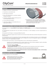
3. Connection of the Components
Portable use
Attach 4 base pads to the bottom of antenna base.
7
ENGLISH GERMAN FRENCH SPANISH DUTCH
3. Operating Instruction
3-1. Connection Diagram
Use the black color controller cable to connect between the controller and
antenna.
The controller cable looks similar to the antenna cable but you can distinguish
them by the color and labeling.
Portable use
Attach 4 Base Pads to the bottom plate
Adaptor or Cigarette light adaptor
Receiver cable
(Grey color)
Controller cable
Controller
Controller
(Black color)
CONTROLLER
MAIN UNIT
RECEIVER
TV
signal cable (7 m)
coax cable (1,5 m)
Television
Cigarette lighter
Control unit
Antenna
Ignition positive
control cable (7 m)

08 ENGLISH
4. Startup and operation
4.1 DIP switch
4.2 Search for the satellite
DIP switches are located on the back of the control unit. The
default setting for the switches is automatic mode (both
DIP switches are in the upper position). You should only use
the antenna in automatic mode. The mode switch is inten-
ded for service, so you should not change the position of
the switch arbitrarily.
checks the position
1. Switch on the control unit. Subsequently, some satellite LEDs will light up. These show
the current firmware version as a binary code. The display usually only serves the
service.
2. As soon as the control unit is ready for operation, one of the satellite LEDs lights up.
3. If you want to search for another satellite, press one of the arrow buttons to select the
desired satellite. Confirm selection with the SET button to start the search.
4. Before the satellite search, the home LED flashes and checks the antenna status (po-
sition). If the antenna is not in the HOME position, the antenna goes into the basic
position before it searches the selected satellite.
automatic
mode
manual
mode
WARNING!
If the antenna is not in automatic mode, it does not function as described in this
manual!
If you still want to operate the antenna in manual mode, no guarantee is granted!
search for satellite /
Binary code shows the
current firmware version
Satellite found

09ENGLISH
4. Startup and operation
4.3 Back to HOME position & Turning o
4.4 Auto-DiSEqC-Function
You can make settings in your receiver or TV DiSEqC. This has
the advantage that the antenna automatically aligns itself with
another satellite. Change to the channel list of your receiver, For
example, from Astra to Hotbird, the antenna is automatically di-
rected to the satellite.
AUTOMATIC
1. If the vehicle travels 25 km/h or faster for at least 20 seconds, the antenna moves back
to the HOME position.
2. When the ignition cable is connected and the ignition key is turned, the antenna
moves back to the HOME position.
MANUAL
1. If you do not want to use the antenna, press the HOME button. The antenna returns to
the HOME position and switches off automatically after approx. 30 seconds.
2. While the antenna is moving to the HOME position, the HOME LED flashes. When the
antenna is in the HOME position, the HOME LED is lit continuously.
1. The settings for the DiSEqC function are switched off by de-
fault.
2. To activate the function, make sure that the antenna is in the
HOME position. Then press the DiSEqC button for 2 seconds.
The DiSEqC LED lights up.
3. So that the antenna switch automatically, you must assign in
your receiver the correct DiSEqC settings. Use the table to assign the respective satel-
lites accordingly.
Note:
If the antenna is not in the HOME position, press the
SET button to activate the DiSEqC function.
LNB Satellit
LNB 1 Turksat
LNB 2 ASTRA2
LNB 3 ASTRA3
LNB 4 ASTRA1
LNB 5 Hot Bird
LNB 6 Etelsat 9
LNB 7 ASTRA 4
LNB 8 Thor
LNB 9 Eutelsat 5W
LNB 10 Hispasat
LNB 11 USER1
LNB 12 USER2

10 ENGLISH
5. Troubleshooting
There are a number of common issues that can affect the signal reception quality or
the operation of the antenna. The following sections address these issues and potential
solutions.
1. Check again all the cable connections have been made correctly.
2. Check if the power input cable has been damaged.
3. Check the battery polarities (+/-).
1. If the antenna does not move into desired position.
2. If the antenna makes a noise whilst remaining static.
1. If the system has been improperly wired, it will not operate properly. Contact
local dealer/shop for assistance of cable damage.
1. Satellite signals can be blocked or degraded by buildings, trees. Make sure there are
no obstructions in a southward direction.
2. Turn the unit off and then back on again and select desired satellite.
3. Switch the control unit off and on again. Select the desired satellite again.
• Connection between the power and controller.
• Connection between the controller and antenna.
• Try to power OFF/ON again.
• Try to power OFF/ON again. If problem persists, please contact local dealer/
shop for assistance.
A. No function when power on the controller
B. Fail to search the selected satellite
C. Mechanical problems
D. Other issues

11ENGLISH
6. Firmware update
1. Copy the new firmware to the root directory of the USB device (without subfolders).
The flash drive must be formatted as a FAT32 file system and must not contain any
other data! You can find the latest firmware on www.megasat.tv
2. Ensure that the unit is turned off and plug the USB into USB port on the side of controller.
3. Press and hold SET button then also press the POWER button.
4. The update starts. During this time, the satellite LEDs will light up one by one.
5. After a successful update, the control unit switches off and restarts.
USB device

12 ENGLISH
7. Mounting dimensions
201 mm
515 mm
454 mm
355 mm
316 mm
126 mm
max. 426 mm
max. 201 mm
Direction of travel
27,5 cm
pivot point
Max. pivot range
66 cm
49,5 cm
35,5 cm
51,5 cm

13ENGLISH
8. Mounting on the roof
FRONT
1
3
2
4
1. Special adhesives
2. Signal cable (7m)
3. Allen key
4. Control unit holder
5. Controller cable (7m)
6. Control unit and cable (1,5m)
7. Friction tape
8. M6 × 15 (8), M4 × 20 (14)
9. Mounting plate
10. Cigarette lighter adaptor
11. Cleaner
12. Drill
13. 2 mm drill, 25 mm drill
14. Gland
15. Roof outlet
3 holes
Direction of travel
Make sure that all the required parts and tools are available before installation:
Clean the surface with cleaner.
Attach friction tape outside of the mounting
plate by 5mm away from the plate edges.
Locate mounting plate in the centre of the
vehicle roof.
Put aside the mounting plate to apply silicone within the
attached tape line but leave 2cm inward gap from the line.

14 ENGLISH
8. Mounting on the roof
Place the mounting plate on the silicone and
make 7 holes (2mm) with a power drill.
Assemble seven (7) of M4x20 bolts
Apply silicone around mounting plate edge
Apply silicone on the holes
Re-apply silicone to cover bolts screwed
Tidy silicone surface
5
9
7
11
6
10
8
12
Remove friction tape and allow to dry Prepare to place the antenna on to the eight
upright bolts

15ENGLISH
8. Mounting on the roof
Parts required, allen wrench and eight(8) of
M6×15 bolts
Place the antenna on the mounting plate and
tighten firmly each of the bolts with allen wrench
13
Place cable holder 40-45 cm away from the rear centre of the antenna. Apply friction tape 5mm from
the outside of the holder
15
14
16 17
Drill a 25mm hole in the centre of the
tape marking
Make sure that hole size is minimum so that the
cable can pass through.
40-45 cm

16 ENGLISH
8. Mounting on the roof
18
19
20
22
21
23
Signal cable, controller cable, cable holder and gland are required.
Set up required parts as above picture.
Place and hold the assembled cable holder inside
the tape markings. Drill three(3) 2mm holes
Fix cable holder on the vehicle roof with
three(3) of M4 x 20 screws on drill holes made
Apply silicone around cable holder and on the
top of the screws for waterproof
Connect cables to relative ports. Remove
friction tape then tidy silicone before dry

17ENGLISH
8. Mounting on the roof
Get cigarette lighter adaptor (power input cable).
24
12V DC
Ignition
Match the power cables polarities to the battery po-
larities, red to red / black to black and white ignition
cable to ignition port of the vehicle.
Place the control unit on a straight surface and
connect all cables.
If you want to attach the control unit to the wall,
use the supplied brackets for mounting and then
connect all cables to the control unit.
Would you like to operate the antenna to the car
battery, remove the adapter and insert the three
wires of the cable free.
Get controller bracket, rear cable cover and four (4)
M4 x 20 bolt.
26
28 29
25
27

18 ENGLISH
9. Specications
General data
LNB output 1
LNB input frequency 10.7 ~ 12.75 GHz
LNB output frequency 950 ~ 2.150 MHz
Polarization horizontal / vertical
Antenna gain 33.7 dBi @ 12.7 GHz
Min EIRP 50 dBW
Skew angle range -45° ~ +45°
Elevation angle range 15° ~ 90°
Azimuth angle range 360°
Search time ca. 1-2 minutes
Operating temperature -30° C to +60° C
Power supply 12 ~ 24 V
Power consumption max. 30 W (at search)
Dimensions (W/H/D) 515 x 201 x 355 mm
Weight 10.3 kg
Note:
Weight and dimensions are not absolutely exact values .
Technical details can be changed at any time without prior notice.
/