Page is loading ...

Installation and Operation Manual
Due to the dynamic nature of product design, the information contained in this
document is subject to change without notice. Broadcast Tools, Inc., assumes no
responsibility for errors and/or omissions contained in this document. Revisions
of this information or new editions may be issued to incorporate such changes.
Broadcast Tools® is a registered trademark of Broadcast Tools, Inc.
Copyright, 1989 - 2005 by Broadcast Tools, Inc. All rights reserved.
No part of this document may be reproduced or distributed without permission.
Visit www.broadcasttools.com for important product update information.
PS-99 firmware version 2.30 or greater
Manual Revised 08/18/2005
PS-99
Programmable Scheduler-99
INC
®

e-mail:
voice:
360.854.9559
fax:
866.783.1742
PS-99 Installation and Operation Manual
Table of Contents
Section Title Page #
Introduction . . . . . . . . . . . . . . . . . . . . . . . . . . . . . . . . . . . . . . . . . . . . . 3
Safety Information . . . . . . . . . . . . . . . . . . . . . . . . . . . . . . . . . . . . . . . . 3
Who to contact for help . . . . . . . . . . . . . . . . . . . . . . . . . . . . . . . . . . . . 3
Product Description . . . . . . . . . . . . . . . . . . . . . . . . . . . . . . . . . . . . . . . 4
Operational Functions . . . . . . . . . . . . . . . . . . . . . . . . . . . . . . . . . . . . . 5
Installation . . . . . . . . . . . . . . . . . . . . . . . . . . . . . . . . . . . . . . . . . . . . . . 6
Inspection . . . . . . . . . . . . . . . . . . . . . . . . . . . . . . . . . . . . . . . . . . . . 6
Bench Test and Programming. . . . . . . . . . . . . . . . . . . . . . . . . . . . . 6
Mounting. . . . . . . . . . . . . . . . . . . . . . . . . . . . . . . . . . . . . . . . . . . . 13
Equipment Connection . . . . . . . . . . . . . . . . . . . . . . . . . . . . . . . . . 13
Specifications . . . . . . . . . . . . . . . . . . . . . . . . . . . . . . . . . . . . . . . . . . . 15
Warranty. . . . . . . . . . . . . . . . . . . . . . . . . . . . . . . . . . . . . . . . . . . . . . . 16
2
CONTENTS

e-mail:
voice:
360.854.9559
fax:
866.783.1742
3
PS-99 Installation and Operation Manual
INTRODUCTION
INTRODUCTION
Thank you for your purchase of a Broadcast Tools® PS-99, Program Scheduler
(referred to as the PS-99 throughout this manual). We’re confident that this product
will give you many years of dependable service. This manual is intended to give you
all the information needed to install and operate the Broadcast Tools® PS-99.
SAFETY INFORMATION
Only qualified personnel should install Broadcast Tools® products. Incorrect or
inappropriate use and/or installation could result in a hazardous condition.
WHO TO CONTACT FOR HELP
If you have any questions regarding your product or you need assistance, please con-
tact your distributor from whom you purchased this equipment.
If you would like more information about Broadcast Tools® products, you may
reach us at:
Broadcast Tools, Inc.
131 State Street
Sedro-Woolley, WA 98284 USA
Voice: 360 . 854 . 9559
Fax: 360 . 854 . 9479
Internet Home Page: www.broadcasttools.com
E-mail: [email protected]
THANK YOU FOR CHOOSING
BROADCAST TOOLS® BRAND PRODUCTS!
CAUTION!
Broadcast Tools®
Products, as with any
electronic device, can
fail without warning.
Do not use this product
in applications where a
life threatening condition
could result due to failure.
NOTE:
This manual should be
read thoroughly before
installation and operation.
WEBSITE:
Visit our web site for
product updates and
additional information
Broadcast Tools is a Veteran Owned Business
Designed, Assembled and Supported in WA State, USA

e-mail:
voice:
360.854.9559
fax:
866.783.1742
4
PS-99 Installation and Operation Manual
DESCRIPTION
PRODUCT DESCRIPTION
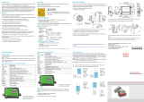
The Programmable Scheduler (PS-99) can store and control up to 99 events. Events
may be programmed with Hour/Minutes/Seconds and Day/Month/Year or Day of
Week. Each event may control the RS-232 serial data port and/or any of the six
SPDT one amp relays. Thirty serial macro strings of up to 96 ASCII, HEX and/or
control characters may be stored and scheduled at specific times.
Events are scheduled using a front panel “PGM” RS-232 serial port and a standard
terminal program such as Windows HyperTerminal or Tera-Term Pro. The PS-99
supports 99 scheduled events. An event can consist of turning a relay on or off, trig-
gering a relay momentarily for 750 ms and/or sending serial control macros out the
rear panel EXT Serial port. Macros can be any ASCII or HEX value, along with
control characters.
Programming is accomplished with any non-dedicated computer and off-the-shelf
communication software.
Features
• Six SPDT one amp relays, with up to sixteen character labels. These may be
configured for either momentary or latched contact closures.
• Thirty, ninety-six (96) character ASCII, HEX and/or control character serial
control macro strings.
• Optically isolated Sync input with LED indicator, allowing clock updates any
minute and second within each hour from an external source, such as NIST,
Program Networks or master clock systems.
• Lithium battery backup keeps the clock processor operating during power out-
ages. 10 plus year life expectancy.
• Stable crystal time-based clock processor.
• Flash based microprocessor with non-volatile memory.
• Field-programmable with a non-dedicated PC.
• Auto leap year correction.
• 24-hour time format.
• Daylight Saving Time programming. Y2K compliant.
• Removable screw terminals for easy connection to your external circuits.
Applications
AM power change, directional array switching, control of satellite receivers;,
analog/AES-EBU/Video switchers, VTR’s or any other device that accepts
RS-232 ASCII and/or HEX control strings and/or relay contact closures.
WEBSITE:
Visit our web site for
product updates and
additional information

e-mail:
voice:
360.854.9559
fax:
866.783.1742
5
PS-99 Installation and Operation Manual
OPERATION
OPERATIONAL FUNCTIONS
EVENTS
Program up to 99 events to any one of six relays and/or 30 serial control macros.
The programming is accomplished when the PS-99 is connected to the serial port of
any non-dedicated computer running off the shelf communication software in either
the DOS, Windows or Windows 95/98/2000/NT/XP based platforms. The PS-99
may also be programmed remotely, when is connected to an optional external
modem.
RELAYS
The PS-99 is supplied with six SPDT one-amp relays. The relays may be config-
ured to latch, unlatch or give 750 ms momentary contact closure. Each relay may
be assigned a sixteen-character label.
EXTERNAL SERIAL CONTROL
The PS-99 provides transmit only RS-232 EXT serial port. Baud rates may be set
to any of the following: 300, 600, 1200, 2400, 4800, 9600, 19.2K, 38.4K and con-
figured to transmit up to thirty, ninety-six (96) character ASCII/HEX control macro
strings.
PGM SERIAL PORT
The PS-99 provides a front panel “PGM” RS-232 serial port. The port is used to
program the PS-99 from a computer. Baud rate is fixed at 9600, N81.
TIME
The PS-99 uses the 24-hour time format.
SYNC INPUT
This input is only active +/- 20 seconds within any programmed minute and second.
The PS-99 ignores this input during all other times. With this in mind, ANY event
scheduled during these times may be SKIPPED.

e-mail:
voice:
360.854.9559
fax:
866.783.1742
6
PS-99 Installation and Operation Manual
INSTALLATION
INSTALLATION
Installation of the PS-99 is simple. The sync input, relay outputs are connected via
removable screw terminals, while the front and rear panel serial ports are equipped
with male and female DB-9 D-Sub connectors. Installation of the PS-99 consists of
four steps: 1 – Inspection, 2 – Bench Test and Programming, 3 – Mounting,
4 – Equipment Connection.
STEP 1: INSPECTION
Please examine your PS-99 carefully for any damage that may have been sustained
during shipping. If any is noted, please notify the shipper immediately and retain
the packaging for inspection by the shipper. The package should contain the PS-99,
9 volt AC @ 1 amp wall transformer, this manual, and two male/female straight-thru
serial cables.
STEP 2: BENCH TEST and PROGRAMMING
Place the PS-99 on a workspace. Connect the supplied serial cable to the PS-99’s
front panel male DB-9 D-sub connector labeled “PGM” and the other end into your
computer’s com port. Plug the supplied 9 volt AC @ 1 amp wall transformer into a
stable source of 117vac @ 60 Hz and the cable end of the wall transformer into the
rear panel 2.1mm power receptacle (J1). Verify that the power LED is lit. The PS-
99’s “PGM” port is fixed at 9600 baud, with 8 data bits, no parity and one stop bit.
Load the communication software package (MS Windows 95/98/ME/2000/NT/XP
HyperTerminal, Tera-Term, etc.) using the protocol of 9600-N-8-1. Set the mode
to DIRECT, Flow Control to NONE, and emulation to ANSI with ECHO ON.
NOTE: To enter the program mode, press the front panel recessed “PGM” but-
ton with a non-metallic object or enter *MM from the PC keyboard.
The following menu will appear
MAIN MENU:
<Esc> to e(X)it (P)arameters
(V)ersion (R)elays & Labels
(T)ime & Date (C)ontrol Macros
(M)enu (E)vent Records
PS99>
NOTE: Wherever a command letter is called for, such as M to redraw the (M)enu,
the lower case letter value (in this case ‘m’) will also be accepted.
NOTE: The Menu will time out after 60 seconds of inactivity. While in menu
mode, events will not be performed.
NOTE:
Installation of the PS-99
in high RF environments
should be performed
with care. Shielded
cable is suggested for
all connections. Shields
and station ground
should be tied to the
chassis screw, located
on the far right side of
the PS-99 as viewed
from the rear. It is rec-
ommended that all
cables connected to the
PS-99 be looped
through ferrite cores to
suppress RF. Surge pro-
tection with RF filtering
such as the Tripp Lite
“ISOBAR 4” is also
suggested for the wall
transformer.

e-mail:
voice:
360.854.9559
fax:
866.783.1742
7
PS-99 Installation and Operation Manual
INSTALLATION
BENCH TEST and PROGRAMMING
<Esc> to e(X)it
The Esc key or an X will exit the menu or back up one level throughout the differ-
ent menus.
(V)ersion – From main menu
Displays the Version:
PS99 VERSIONS:
Firmware: PS99 2.30
EEProm: PS99 2.30
(T)ime & Date– From main menu
Selecting a T will display:
DATE & TIME:
<Esc> to e(X)it; (S)et:
01/01/00 01:23:43 > It will display the current time and allow you to set it.
The program will show the real-time date and time until it times out after 60 seconds
of inactivity, and redraws the main menu (which will also time out after additional
inactivity). To keep the date: time display active longer, pressing any non-command
key (such as space bar) will re-load the timeout timer with an additional 60 seconds.
To set, enter an S
SET DATE & TIME:
<Esc> to e(X)it; Type new value; <Enter> to accept.
Month 01 > Enter the two-digit month followed by a CR, example: 02(CR)
Date 01 > Enter the two-digit day of the month, example: 05(CR)
Year 00 > Enter the two-digit year, example: 04(CR)
Hour 01 > Enter the two-digit hour, example: 17(CR) –
Always use 24-hour time format.
Minute 28 > Enter the two digit minute, example: 02(CR)
Second 07 > Enter the two digit second, example: 15(CR)
If you leave before reaching this point, the entries will not be saved. Upon entering
a (CR) after the seconds entry, the clock will be set and the data saved. When you
enter the seconds value, it will not be set until you press the Enter key. This allows
you to enter a value that is ahead in time and hit the Enter key when the desired sec-
ond rolls over.
NOTE:
The time should be set
using a stable time ref-
erence. You may use
your Program Network,
or call the National
Institute of Science and
Technology (NIST) at
1-303-499-7111.
WEBSITE:
Visit our web site for
product updates and
additional information

e-mail:
voice:
360.854.9559
fax:
866.783.1742
8
PS-99 Installation and Operation Manual
INSTALLATION
(P)arameters– From main menu
PARAMETERS:
<Esc> to e(X)it; (D)ST: No; (S)ync: 00:00; (B)aud: 9600;
(R)eset ALL (Params, Relay Labels, Macros, Events):
PS99>
(D)ST: No
Entering a D will toggle the “Daylight Savings” flag on and off. Doing this does not
change the time. With DST set to No, it allows you to select Spring Ahead as an
event option. With DST set to Yes, it allows you to select Fall Back as an event
option. When Spring Ahead or Fall Back events are executed, the DST flag will
automatically change. For example, if you are currently in standard time and have
the DST option set to No, you could set up a Spring Ahead event to occur at 0200
hours on 05/01/2004. At that time, the clock will be set one hour ahead and the DST
flag will be changed to Yes.
(S)ync: 00:00; Selecting an S will display:
EDIT SYNC
Sync 00:00 > Enter 4 digits (without a colon) to indicate the minute and second that the
sync pulse is received from your sync source. For example, if the sync pulse is sent
every hour at 54 minutes and 30 seconds, enter 5430(CR). Do not schedule any events
for the same second that a Sync pulse is to be received, or they may be missed since the
time may be slightly adjusted. When a sync input is received, the real time clock will
sync up to the time specified. For example, if the sync is set for 54 minutes, 30 seconds
and the clock is reading 54:29d when a sync pulse is received, it will immediately be
adjusted to 54:30. Sync pulses that are received outside of the “Sync Window” of +/- 20
seconds will be ignored. So if there are multiple sync pulses during the hour, only the
pulse that is detected within 20 seconds of the target time will be acted upon.
(B)aud: 9600
With each entry of the B key, the baud rate for event macros will cycle through the
various baud rate selections. The possible values are 300, 600, 1200, 2400, 4800,
9600, 19.2K and 38.4K. The menu selection will be re-written each time with the
new value. This only affects the setting of the event macro output port, the data
coming out of the DB-9 male connector on the rear panel. Data is always output at
8,N,1, regardless of the baud rate. The programming port is always set to 9600
baud.
(R)eset ALL (Params, Relay Labels, Macros, Events)
PS99> Enter an R to reset to factory defaults. Warning: This will erase all macros
and events.
(C)onfirm RESET ALL ? > It gives you a chance to back out. A C must be entered
to execute the reset all command.

e-mail:
voice:
360.854.9559
fax:
866.783.1742
9
PS-99 Installation and Operation Manual
INSTALLATION
(R)elays & Labels – From main menu
An R allows you to edit and test relays. The following menu will be displayed:
RELAYS:
# *-Relay Label--* # *-Relay Label--*
1 Relay 1 4 Relay 4
2 Relay 2 5 Relay 5
3 Relay 3 6 Relay 6
<Esc> to e(X)it; (M)enu; All relays of(F);
1-6 = Select Relay; (R)eset Labels:
PS99>
All relays of(F); An F will turn all relays off.
Entering a numerical value 1-6 will select the corresponding relay. For example,
entering a 1 will display:
RELAY 1 "Relay 1": <Esc> to e(X)it; (M)enu;
1-6 = Select Relay; (E)dit Label; of(F); (P)ulse; o(N):
PS99>
An E will display:
EDIT RELAY 1 "Relay 1": <Esc> to exit; <Enter> to accept:
Type New Value> Now you can enter a new label for Relay 1. For example, enter
“High Power”(CR). The label can be up to 16 characters long.
o(N): N Will turn on the selected relay.
of(F): F Will turn off the selected relay.
(P)ulse: P Will pulse the selected relay.
(R)eset Labels: R will reset all of the relay labels back to factory defaults.
(C)ontrol Macros– From main menu
Entering a C will display the first of six Macro pages, 32 characters per line, 3 lines
per macro with 96 total characters for each of 30 macros:
CONTROL MACROS:
## *-------ASCII Macro Data-------*
01 Now is the time for all good men
01 to come to the aid of their cou
01 ntry. Peter Piper picked a peck
02
02
02
03
03
03
04
04
04
05
05
05

e-mail:
voice:
360.854.9559
fax:
866.783.1742
10
PS-99 Installation and Operation Manual
INSTALLATION
(P)age(1-6); (H)ex; (S)elect; (C)lear Page; <Esc> to e(X)it:
PS99>
(P)age; Displays the next page of 5 macros.
(H)ex; / (A)SCII; Toggles back and forth between displaying the macro data in
ASCII and Hex values.
(C)lear Page; erases all macro data on the selected page.
(S)elect; An S will display:
SELECT MACRO:
Number> Enter a two digit macro number. For example, to edit macro 1, you must
enter 01. The following will be displayed:
CONTROL MACRO 01: "Now is the time for all good men"
" to come to the aid of their cou"
"ntry. Peter Piper picked a peck"
00------------07 08------------0F 10------------17 18------------1F
4E6F77206973207468652074696D6520666F7220616C6C20 676F6F64206D656E
20746F20636F6D65 20746F2074686520 616964206F662074 6865697220636F75
6E7472792E202050 6574657220506970 6572207061636B65 642061207065636B
(P)revious; (E)dit; (N)ext; (C)lear; (S)end; <Esc> to e(X)it:
PS99>
The ASCII value of the macro will be displayed on the top line with the correspon-
ding Hex values below. The 00--------07, etc, are place markers that show the loca-
tions of the Hex digits.
(P)revious; Selects the previous macro, for example, if macro 01 is selected, previ-
ous will select macro 30.
(E)dit; will display:
EDIT MACRO 01: <Enter> ends the macro; <Esc> to exit;
To embed chars, type: \\ \bs \esc \cr \lf \<hex> \ctl<A-z>:
Macro 01: 1 = 01-08>Now is t
2 = 09-16>he time
3 = 17-24>for all
4 = 25-32>good men
5 = 33-40> to come
6 = 41-48> to the
7 = 49-56>aid of t
8 = 57-64>heir cou
9 = 65-72>ntry. P
A = 73-80>eter Pip
B = 81-88>er picke
C = 89-96>d a peck
A = 73-80>eter Pip
B = 81-88>er packe
C = 89-96>d a peck
Select Start-Edit Line (1-9,A,B,C)>
Enter New Macro>Enter New Macro> Select a line number to edit, 1-9 or A,B,C,D.
WEBSITE:
Visit our web site for
product updates and
additional information

e-mail:
voice:
360.854.9559
fax:
866.783.1742
11
PS-99 Installation and Operation Manual
INSTALLATION
Macros are edited in sections of 8 characters so that you can easily edit long hex
strings. When entering macros longer than 8 characters, select the starting point and
begin typing. The program will automatically increment to the next segment. So if
you are entering a long ASCII string select “1” and begin typing.
Enter the new macro data followed by a (CR). Control or Hex characters can be
embedded in an ASCII or HEX data string. Possible values are: \bs = Back Space,
\esc = Escape Control Character, \cr = Carriage Return, \lf = Line Feed, \<hex> =
Enter any Hex value after the “\”, 00 – FF, \ctl = any CTL + A through Z for stan-
dard control characters, for example, CTL-C = \ctlC
(C)lear; Will clear or erase the macro
(S)end; Will send the macro out the data port so you can test it.
(P)revious; Selects previous macro
(N)ext; Selects next macro
(E)vent Records – From Main Menu
An E will display one of nine event pages with 11 events displayed on each page.
EVENT RECORDS:
SMTWTFS
## mm/dd/yy hh:mm:ss *-----------Action-----------*
01 01/01/00 00:00:00 No Action
02 01/01/00 00:00:00 No Action
03 01/01/00 00:00:00 No Action
04 01/01/00 00:00:00 No Action
05 01/01/00 00:00:00 No Action
06 01/01/00 00:00:00 No Action
07 01/01/00 00:00:00 No Action
08 01/01/00 00:00:00 No Action
09 01/01/00 00:00:00 No Action
10 01/01/00 00:00:00 No Action
11 01/01/00 00:00:00 No Action
(P)revious; (C)lear Page; (N)ext; (S)elect; <Esc> to e(X)it:
PS99>
(P)revious; Display previous page
(C)lear Page; Clear all macros on the page and set back to No Action
(N)ext; Display next page
(S)elect; will display:
SELECT EVENT:
Number> Enter two digit event number
EVENT RECORD:
SMTWTFS
## mm/dd/yy hh:mm:ss *-----------Action-----------*
01 01/01/00 00:00:00 No Action
(P)revious; (C)lear; (N)ext; (E)dit; <Esc> to e(X)it:

e-mail:
voice:
360.854.9559
fax:
866.783.1742
12
PS-99 Installation and Operation Manual
INSTALLATION
PS99>
(E)dit; An “E” will display:
EDIT EVENT RECORD 01:
(A)ll; (P)revious; (C)urrent; (N)ext; Type new value; <Enter> to accept.
DAY/DATE = DATE > Use the space bar to toggle between DATE and DAY then
press the Enter key. If you select DATE (CR) for setting up an event or events to
happen on a specific date, you will see:
Month 01 > Enter a two digit month value, example: 02(CR)
Date 01 > Enter a two digit date, example 25(CR)
Year 00 > Enter a two digit year, example 04(CR)
Hour 00 > Enter a two digit hour, example 20(CR) – use 24 hour time
Minute 00 > Enter a two digit minute, example 35(CR)
Second 00 > Enter a two digit second, example 00(CR)
The A for All or Wild Card can also be used to select All Months, Days, Years,
Hours, Minutes or Seconds. For example, you could set up an event to be generat-
ed every hour on July 4th.
DAY/DATE = DAY > If DAY is selected, the following will be displayed:
WeekDay ------S > Enter 1-7 (Sunday being 1, Saturday 7) to set or toggle days of
the week on or off, for example to set it to trigger an event every Sunday, Monday
and Tuesday, enter 123. To turn off Saturday, if it is already set, enter a 7. To select
All days, use the A to toggle the “All” Days wild card values (*******) on and off.
Note: If the wild card “*” values have been selected, they must first be de-selected
with an A before new numeric values can be entered.
The Hour, Minutes and Seconds will also be displayed and can be changed as in the
above examples.
The next selection for both Day and Date is the Action to take place:
Action: No Action > Hitting the space bar will cycle through the possible options,
selecting one of the relay options; Relay Off, Relay On, Relay Pulse (CR) will bring
up:
RELAYS:
# *-Relay Label--* # *-Relay Label--*
1 Relay 1 4 Relay 4
2 Relay 2 5 Relay 5
3 Relay 3 6 Relay 6
Relay 1 > Enter the relay number followed by a return. This will select the relay to
be turned off, pulsed or turned on.
WEBSITE:
Visit our web site for
product updates and
additional information

e-mail:
voice:
360.854.9559
fax:
866.783.1742
13
PS-99 Installation and Operation Manual
INSTALLATION
If the Macro action is selected, it will prompt you for the macro number:
Action: Macro 07 >
Action: Spring Ahead – Will set the PS-99 to transition from Standard to Daylight
Savings time at the specified event time. For this option to work, the DST setting in
the Parameters Menu (from the Main Menu) must be set to No, showing that the PS-
99 is currently operating in Standard time.
Action: Fall Back > – Will set the PS-99 to transition from Daylight to Standard
time. For this option to work, the DST setting in the Parameters Menu (from the
Main Menu) must be set to yes, showing that the PS-99 is currently operating in
Daylight Savings time.
After you have finished entering the event record, the individual record will be dis-
played. Hitting the Esc key will display all the records for the current page.
After you are finished editing Events, escape out of the menu and exit. If sixty sec-
onds elapse without any data entry, the menu will time out and the PS-99 will go
back into operational mode. You must exit the menu, or time out, before events will
be generated.
STEP 3: MOUNTING
Mount the unit on a rack shelf, such as the Broadcast Tools RA-1, allowing adequate
airflow for cooling. The optional RA-1 may be ordered separately for rack mounting.
STEP 4: EQUIPMENT CONNECTION
The PS-99 interfaces to your equipment through the rear panel connectors. Follow
the rear panel labels for the sync input and relay connections. Connections to the
removable screw terminals should be made using 22 AWG or smaller solid or strand-
ed wire. Strip off approximately 3/16” from the connection end of the wire.
Remove the plug from the connector and insert the wire into the plug. With a small
screwdriver, tighten the setscrew. Reinstall the plug into the appropriate connector.
Connect the computer and external serial device to the desired connectors.

e-mail:
voice:
360.854.9559
fax:
866.783.1742
14
PS-99 Installation and Operation Manual
CONNECTION
EQUIPMENT CONNECTION
SYNC INPUT
Determine if your sync source is of the dry or wet format. A wet source would be
something supplying voltage, and the dry source would be the following: Relay or
switch contacts, Open collector, etc. The PS-99 is shipped set up for dry operation
(JP-1, both jumpers in place). The sync input may be tested by shorting the TS INA
(Gnd or anode) and TS INB (cathode) terminals together. Verify this by the GREEN
“SYNC” LED lighting. To change the Sync input to wet operation, remove both
jumpers and install one jumper on pins 2 & 3 of JP-1. The source voltage may range
from 5 to 24 volts DC. To use the 5-volt TTL compatible sync input, connect the
external contact between the TS INC and GND. The correct polarity must be
observed.
RELAY OUTPUTS
Follow the labels on the rear panel for the desired relay connections. Each relay is
described with the relay number denoting the Common (wiper), Normally Open or
Normally Closed contacts. When the desired relay is programmed, the PS-99 will
perform the command which is selected, either latch, unlatch or a 750 ms momen-
tary closure.
NOTE:
The PS-99 is not con-
nected to the power-
line ground, since the
AC wall transformer is
isolated; however, the
PS-99 is internally con-
nected to the circuit
ground and the metal
enclosure of the PS-99
via a parallel .001 uf
cap and 10 ohm resis-
tor. The station ground
should be connected to
the chassis mounting
screw.

e-mail:
voice:
360.854.9559
fax:
866.783.1742
15
PS-99 Installation and Operation Manual
SPECIFICATIONS
SPECIFICATIONS
Logic: Flash microprocessor, non-volatile event and
macro programming memory.
Time Base: Stable crystal time-based clock processor.
Stability at approximately fifty seconds per month.
NOTE: We recommend using an accurate
external time sync source, such as the tiny
TOOLS “Time Sync Plus” to insure network
timing stability.
Sync input: Optically isolated wet or dry input, 5 to 24vdc
and/or 5 volt TTL compatible. Sync input with
front panel LED indicator. Clock updates may be
set for any minute and second within each hour.
Backup System: Lithium battery. 10 plus year life expectancy.
PGM Serial Communication: Serial - Asynchronous, Fixed, 9600 baud,
8N1. Level: RS-232C. Front panel LED data indi-
cator.
EXT Serial Communication: Serial - Asynchronous, 300, 600, 1200
2400,4800,9600.19.2K, 38.4K baud, 8N1.
Level: RS-232C. Factory default 9600,8N1.
Front panel LED data indicator.
Relays: Sealed relays, utilizing SPDT Bifurcated-Crossbar
Silver alloy with gold overlay contacts. 1 Amp/30
vdc.
CAUTION!: For safety, do NOT connect 120
Volt circuits to the relays.
Connectors: Relay/Sync Opto - Removable screw terminals.
Serial - EXT, Male DB-9
Serial - PGM, Female DB-9
Two - Straight-thru male/female cables supplied.
Power Requirements: 9 Vac @ 500 ma or 1 amp, 120 Vac 50-60 hz wall
transformer ssupplied. (CE 240 Vac 50-60 hz
optional)
Size: 5.65” x 6.50” x 1.55” (WDH)
Weight: 2.0 lbs.
Options: RA-1 rack shelf for mounting up to three units in
1-RU,
Tiny TOOLS™ Time Sync Plus
Broadcast Tools ® ESS-1, Ethernet to Serial
Server.
Broadcast Tools® USB-RS232, USB to Serial
converter.
WEBSITE:
Visit our web site for
product updates and
additional information

16
PS-99 Installation and Operation Manual
LIMITED WARRANTY
LIMITED WARRANTY
The term “Buyer” as used in this document refers to and includes both (but only) (a) any person or entity who acquires such an item for
the purpose of resale to others (i.e., a dealer or distributor of an item), and (b) the first person or entity who acquires such an item for
such person’s or entity’s own use.
Broadcast Tools warrants to each Buyer of any item manufactured by Broadcast Tools that the item will be free from defects in materi-
als and workmanship at the time it is shipped by Broadcast Tools if the item is properly installed, used and maintained.
EXCLUSIVE REMEDIES
If Broadcast Tools is notified, in writing, of a failure of any item manufactured by Broadcast Tools to conform to the foregoing Limited
Warranty within one (1) year following the date of the Buyer’s acquisition of the item, and if the item is returned to Broadcast Tools in
accordance with Broadcast Tools’ instructions for confirmation by inspection of the defect (which at Broadcast Tools’ election may
include, without limitation, a requirement that the Buyer first obtain a Return Authorization number from Broadcast Tools, that the Buyer
furnish proof of purchase in the form of an invoice and/or receipt, and that the Buyer prepay all freight charges associated with any return
of the item to Broadcast Tools using such freight service as Broadcast Tools reasonably may specify), Broadcast Tools will repair or
replace the defective item, or will refund the purchase price paid by the Buyer for the item. Broadcast Tools shall have the exclusive
right to choose between these alternative remedies.
NO OTHER WARRANTIES OR REMEDIES
TO THE MAXIMUM EXTENT PERMITTED BY APPLICABLE LAW, BROADCAST TOOLS AND ITS SUPPLIERS DISCLAIM ALL OTHER
WARRANTIES, EITHER EXPRESS OR IMPLIED, INCLUDING BUT NOT LIMITED TO IMPLIED WARRANTIES OF MERCHANTABIL-
ITY OR FITNESS FOR A PARTICULAR PURPOSE; AND THE FOREGOING ALTERNATIVE REMEDIES SHALL BE EXCLUSIVE OF
ALL OTHER REMEDIES. THIS LIMITED WARRANTY GIVES YOU SPECIFIC LEGAL RIGHTS. YOU MAY HAVE OTHER RIGHTS,
WHICH VARY FROM STATE/JURISDICTION TO STATE/JURISDICTION.
NO LIABILITY FOR CONSEQUENTIAL DAMAGES
TO THE MAXIMUM EXTENT PERMITTED BY APPLICABLE LAW, NEITHER BROADCAST TOOLS NOR ANY OF ITS SUPPLIERS
SHALL HAVE ANY LIABILITY FOR ANY SPECIAL, INCIDENTAL, INDIRECT, CONSEQUENTIAL OR PUNITIVE DAMAGES WHATSO-
EVER (INCLUDING, WITHOUT LIMITATION, ANY DAMAGES FOR LOST PROFITS, BUSINESS INTERRUPTION, LOSS OF DATA OR
INFORMATION, COST OF CAPITAL, CLAIMS OF CUSTOMERS, OR ANY OTHER PECUNIARY LOSS) ARISING OUT OF THE USE
OF OR THE INABILITY TO USE ANY ITEM SUPPLIED BY BROADCAST TOOLS, EVEN IF BROADCAST TOOLS HAS BEEN
ADVISED OF THE POSSIBILITY OF SUCH DAMAGES HAVE ANY LIABILITY FOR ANY SPECIAL, INCIDENTAL, CONSEQUENTIAL,
EXEMPLARY OR PUNITIVE DAMAGES. THIS LIMITATION OF LIABILITY APPLIES WHETHER A CLAIM IS ONE ALLEGING
BREACH OF A CONTRACT OR WARRANTY, NEGLIGENCE OR OTHER TORT, FOR THE VIOLATION OF ANY STATUTORY DUTY,
THE FAILURE OF ANY LIMITED OR EXCLUSIVE REMEDY TO ACHIEVE ITS ESSENTIAL PURPOSE, OR ANY OTHER CLAIM OF
ANY NATURE. BECAUSE SOME STATES AND JURISDICTIONS DO NOT ALLOW THE EXCLUSION OR LIMITATION OF LIABILITY
FOR INCIDENTAL OR CONSEQUENTIAL DAMAGES, THIS LIMITATION MAY NOT APPLY TO YOU.
Broadcast Tools, Inc.
131 State Street
Sedro-Woolley, WA 98284 • USA
360.854.9559
voice • 866.783.1742 fax
suppor[email protected] e-mail
www.broadcasttools.com website
e-mail:
voice:
360.854.9559
fax:
866.783.1742
/