Page is loading ...

© 2016 Precision Digital Corporation.
All rights reserved.
Thank you for your purchase of the
PD6000 process meter.
describe some of the common setup
procedures for this meter.
This guide includes:
Basic Wiring for Meter..............
Program and Scale the Input...............
Program Relays for Automatic Reset...
Program Custom Unit Tags..................
Program 4-20 mA Analog Output.........
Reset Meter to Factory Defaults..........
For additional information about the
PD6000 meter not covered in
this quick start guide, please consult
the instruction manual included on the
CD or available at www.predig.com.
Menu Button – Use this button to
access Programming Mode and to
return to Run Mode.
Note: If you think you have made a mistake while
programming the meter, use this button to
return the meter to Run Mode without saving.
Right/F1 Button – Use this button to
change the selected digit while input-
ting a numeric value in Programming Mode.
Up/F2 Button – Use this button to
increment the selected digit while
inputting a numeric value in Programming
Mode.
Enter/F3 Button – Use this but-
ton to access or accept a menu
item while in Programming Mode.
2
3
4
5
6
7
8
P
R
V
U
S
ERIES
®
233 South Street
Hopkinton MA 01748-2208 USA
Tel. (508) 655-7300 www.predig.com
MeterView Pro
USB Install
PD6000 Process Meter
Quick Start Guide

2
onboard USB. The meter is powered by the USB connection, so there is no need to wire
anything prior to programming the meter.
®
Pro
Connect the provided USB cable to the
meter and the computer as shown. The
computer will automatically install the driver
software it needs to talk to the meter.
Note: Only one meter may be connected at a time.
with the meter software.
Once the driver is installed, an AutoPlay dialog
should appear for the drive “MAINSTAL.” Click
If the computer does not display an AutoPlay
dialog for the drive “MAINSTAL,” you should
open My Computer and double-click on the
drive labeled “MAINSTAL.”
The program will open a few windows and
install two programs on your computer. Simply
follow the onscreen instructions until you see
one of the dialogs in step 4.
Note: If you receive a User Account Control
warning, click “Yes.”
If there is an update available, click the
“Update” button to install the new version.
-
ming your meter.
Note:-
ware, you will be asked if you want to update
This way, you will always have the most cur-
rent version on the meter for future installs.
Note:
1 2
3
4
PD6000 Process Meter Quick Start Guide

3
-
nectors. Connect your wires to the provided connectors and plug into the meter as indicated.
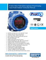
Basic Wiring for Meter
4-20 mA Input Wiring
Wiring for a 4-20 mA input using either an external
power supply or self powered transmitter.
Wiring for a 4-20 mA input using internal power
supply.
4-20 mA Output Wiring
1
Relay Connections
2
AC and DC
Loads Protection
Loads Protection
F4 Digital Input Connection
1
2
Consult the PD6000 instruction
manual located on the included CD
or available online at www.predig.com
for additional wiring diagrams.
Active
Passive
+ -- +
External
Power
Supply
2-Wire
4-20 mA
Transmitter
INPUT SIGNAL
- +
INPUT SIGNAL
2-Wire 4-20 mA
Self-Powered
Transmitter
P- COMP+ V+ mA+
3 41 2 5
F4
6
P- COMP+ V+ mA+
3 4
1
2 5
F4
6
-+
INPUT SIGNAL
3-Wire 4-20 mA
Transmitter
Signal
+
-
2-Wire 4-20 mA
Transmitter
INPUT SIGNAL
P- COMP+ V+ mA+
3 41 2 5
F4
6
P- COMP+ V+ mA+
3 41 2 5
F4
6
-+
+
Voltage
Signal
INPUT SIGNAL
INPUT SIGNAL
3-Wire Voltage
Transducer
Signal
-
P- COMP+ V+ mA+
3 41 2 5
F4
6
P- COMP+ V+ mA+
3 41 2 5
F4
6
12-35 VDC
Power
Supply
+
4-20 mA
Input Meter
-+
RI- I+
13 2
RELAY1
3 2 1
24 V
-
4-20 mA Input
Remote Display,
Chart Recorder, Etc.
-
+
RI- I+
MA OUT
13 2
RELAY1
3 2 1
24 V
MA OUT
C NONO NC NC C
RELAY4 RELAY3
4 36 5 2 1
C NONO NC NC C
RELAY2 RELAY1
4 36 5 2 1
C
R
C
R
P- COMP+ V+ mA+
3 41 2 5
F4
6
AC or DC
POWER
Required External Fuse:
5 A max, 250 V Slow Blow
POWER
+
-
PD6000 Process Meter Quick Start Guide

4
Program and Scale the Input
Program the
InP 1 &
InP 2
For example: If the meter were used to display the level of a 100 ft tall tank, the transmitter should send
a 4 mA signal when the tank is empty and a 20 mA signal when the tank is full. The meter should be
programmed to interpret these inputs on a display range of 0-100, so that at 4 mA the meter will display
0.00 and at 20 mA the meter will display 100.00.
Press to
enter Programming
Mode, press
to
access the SEtup
Press
to ac-
cess the InPut
Press
to select
-
age (mA or Volt
and press
to accept the input type.
Press multiple
times, until the dec
pt
menu is displayed and press to access.
Press until the
desired decimal
point location is
displayed and press to accept.
Press
to ac-
cess the d-SCAL
press to select yes or no, then press .
Note: Most applications only require one scaling
point (select no
On the Setup tab, un-
der Input Type, select
the desired input.
On the Program-
ming tab, select the
desired decimal
point location.
Under Scale Values,
enter the desired
low and high display
values in the Display column.
Click the Send
Meter Data button
to send your programmed settings to the
meter.
1 2
3 4
1 2
3
5 6
4
PD6000 Process Meter Quick Start Guide

5
Press
to
access the ProG
Press
to ac-
cess the SCALE
Press three
times, until dis 1
is displayed. Use
to change which
digit is selected and
to increment the
selected digit. Press
when done.
Press three
times, until dis 2
(High Display
Use
to change
which digit is selected and
to increment
the selected digit. Press
when done.
Press
to return to Run Mode.
Program Relays for Automatic Reset
Program the
relays at reset points.
Note: If the set point is higher than the reset point, the relay will be a high alarm. If the set point is
than the reset point, the relay will be a .
On the Relays tab,
in the desired relay
section, select “Auto”
from the Action drop
down list.
Enter the set and
reset point values in
Click the Send
Meter Data button
to send your programmed settings to the
meter.
Note:
programmed in this manner. It is
not necessary to send your pro-
grammed settings to the meter after
each relay is programmed, simply
repeat steps 1 & 2 for each relay
then send to the meter.
1 2
3
Press to
enter Programming
Mode, press
to
access the SEtup
Press
until
the relay
menu is displayed
and then press
to access.
7 8
9 10
1 2
PD6000 Process Meter Quick Start Guide

6
Press
until the
appropriate relay
number is displayed
(rly 1-8press
to access.
Press
to accept
Auto (Automatic
Press to access
the set (Relay Set
Use
to change
which digit is
selected and
to increment the selected digit. Press
when done to accept the new set point
value.
Press
to access
the rst (Relay Re-
Use
to change
which digit is
selected and
to increment the selected digit. Press
when done to accept the new set point
value. Press
to return to Run Mode.
Press
to access
the Act (Relay Ac-
Note: Use
during step 3. If you need to pro-
gram more relays, simply repeat
steps 3-9 for each additional relay.
Consult the PD6000 Instruc-
tion Manual for information on
additional relay action types.
Program Custom Unit Tags
Program the meter to display custom unit tags for the process value. Display line 2
shows this custom unit tag by default.
Note:
custom unit tag is simply for ease of reading.
On the Setup tab, in
the Display section,
enter your desired
count as two because they require two LEDs.
Click the Send
Meter Data button
to send your programmed settings to the
meter.
1 2
3
5
7
6
8
9
4
PD6000 Process Meter Quick Start Guide

7
Press to
enter Programming
Mode, press
to
access the SEtup
Press
until the
units
is displayed and
then press
to access.
The meter will
display the default
here that the letter 'm' uses two 7 segment
LEDs. This is true of the letter 'w' as well.
Use
to change
which letter is
selected and
to
increment to the next letter. Press
when
done to accept the new custom unit tag.
Program 4-20 mA Analog Output
Program the meter to output an analog signal based on its display value. This signal
is commonly output to a PLC or chart recorder.
Note: The display values programmed for 4-20 analog output do not need to be the same as those
programmed as input scale values, though they most commonly will be.
On the Setup tab,
under Analog Out
Scale, enter your
Click the Send
Meter Data button
to send your programmed settings to the
meter.
1
2
Press to
enter Programming
Mode, press
to
access the SEtup
Press
until the
aout
menu is displayed
and then press
to access.
Press
to access
the dis 1 (Display
This is the
display value at which the low range of the
output will be transmitted.
Use to change
which digit is
selected and
to increment the selected digit. Press
when done to accept the new display value.
1 2
3 4
1
2
3 4
PD6000 Process Meter Quick Start Guide

LIM6000QS_C - 06/168
Press
to access
the Out 1 (Output
This is the
output signal which represents diS 1.
The default value
of 04.000 (4.000
most applications. Press
to accept.
Press
to ac-
cess the
dis 1
menu. This is the display value at which the
high range of the output will be transmitted.
Use to change
which digit is
selected and
to
increment the digit. Press
when done.
Press
to access
the
Out 2
menu. This is the output signal which repre-
sents diS 2.
The default value of
20.000
should work for
most applications. Press
to accept the
default value.
Return Meter to Factory Defaults
If a mistake has been made while programming the meter and it is unclear where the error
occurred, the best option may be to perform a factory reset of the meter and begin again.
Press and hold
enter the Advanced
Features menu.
Press until the
diAG
menu is displayed.
Press and hold
until the meter
rESEt
to reset the
meter.
The meter will
segments and then
display ProcES
On the Advanced Features
tab, in the bottom left-hand corner, click the
Reset Meter Factory Defaults button.
-
dow that appears, click
OK. The meter will reset to factory defaults.
1
2
5
7
6
8
9 10
1 2
3 4
PD6000 Process Meter Quick Start Guide
/