Page is loading ...


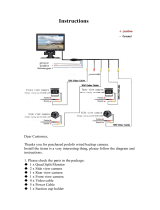
What’s in the Box?
• 1 Color CCD Infra-red Weather Proof Camera
• 1 7" TFT LCD Color Monitor w/Universal Mount/Stand & Wire
• 1 Power Harness
• 1 66’ Camera Cable
• 1 Remote Control
• 1 Power Connection Wire
• 1 Double RCA + Power Converter
(to connect external audio, video and power)
• 1 Screw Kit for installation
REAR VIEW SAFETY
2

3
Table of Contents
Introduction...................................................................................................4
Safety Information ..................................................................................5-7
Before Beginning Installation...................................................................8
Installation Guide.........................................................................................9
Wiring Camera & Monitor.................................................................10-11
Installation Diagram .................................................................................12
Installing the Monitor ..............................................................................13
Monitor Operation.....................................................................................14
Splitting & Splicing ...................................................................................15
Positioning.................................................................................................. 16
Monitor Dimensions..................................................................................17
Monitor Specifications.............................................................................18
Camera Dimensions...................................................................................19
Camera Specifications..............................................................................20
Troubleshooting..........................................................................................21
Warranty.......................................................................................................22
Disclaimer ....................................................................................................23
Reverse With Confidence
™

REAR VIEW SAFETY
4
Introduction
Congratulations on purchasing a Rear View Backup Camera
System! With this manual you will be able to properly install and
operate the unit.
The Backup Camera System is intended to be installed as a
supplement aid to your standard rear view mirror that already
exists in your vehicle. The Backup Camera System should not be
used as a substitute for the standard rear view mirror or for any
other mirror that exists in your vehicle.
In some jurisdictions, it is unlawful for a person to drive a
motor vehicle equipped with a TV viewer or screen located
forward of the back of the driver’s seat or in any location that
is visible, directly or indirectly, to the driver while operating the
vehicle.
Please read all of the installation instructions
carefully before installing the product. Improper
installation will void manufacturer’s warranty.

5
Reverse With Confidence
™
Safety Information
Please read the entire manual and follow the instructions and
warnings carefully. Failure to do so can cause serious damage
and/or injury, including loss of life. Be sure to obey all applica-
ble local traffic and motor vehicle regulations as it pertains to
this product.
Improper installation will void manufacturer’s
warranty.
USAGE
•
The Rear View Camera System
is designed to help the driver
safely detect people and/or
objects helping to avoid
damage or injury. However,
you the driver, must use it
properly. Use of this system is
not a substitute for safe,
proper or legal driving.
• Never back up while looking
at the monitor alone. You
should always check behind
and around the vehicle when
backing up, in the same way
as you would if the vehicle
did not have the Rear View
Camera System. If you back
up while looking only at the
monitor, you may cause
damage or injury. Always
back up slowly.
• The Rear View Camera Sys-
tem is not intended for use
during exstensive back-up
maneuvers or backing into
cross traffic or pedestrian
walkways.
• Please, always remember,
the area displayed by the
Rear View Camera System is
limited. It does not display
the entire panorama that is
behind you.

REAR VIEW SAFETY
6
INSTALLATION
• Electric shock or product
malfunction may occur if
this product is installed
incorrectly.
• Use this product within
the voltage range specified.
Failure to do so can cause
electronic shock or product
malfunction.
• Take special care when
cleaning the monitor.
• Make sure to firmly affix the
product before use.
• If smoke or a burning smell
is detected, disconnect the
system immediately.
• Where the power cable may
touch a metal case, cover the
cable with a friction tape. A
short circuit or disconnected
wire may cause a fire.
• While installing the Rear
View System be careful with
the wire positioning in order
to avoid wire damage.
• The Rear View System should
only be used when the
vehicle is in reverse.
• Do not watch movies or
operate the monitor while
driving; as it may cause an
accident.
• Do not install the monitor
where it may obstruct drivers
view or obstruct an air bag
device.
• Dropping the unit may cause
possible mechanical failure.
Safety Information

7
Reverse With Confidence
™
Safety Information
IN NO EVENT SHALL SELLER OR MANUFACTURER BE
LIABLE FOR ANY DIRECT OR CONSEQUENTIAL DAMAGES OF
ANY NATURE, OR LOSSES OR EXPENSES RESULTING FROM
ANY DEFECTIVE PRODUCT OR THE USE OF ANY PRODUCT.
If you have questions about this product, contact:
Customer Service:
Rear View Safety
1797 Atlantic Avenue
Brooklyn, NY 11233
Tel: 800.764.1028

REAR VIEW SAFETY
8
Before Beginning Installation
Before drilling please check that no cable or wiring is on the
other side of the wall. Please clamp all wires securely to reduce
the possibility of them being damaged while vehicle is in use.
Keep all cables away from hot or moving parts and electrical
noisy components.
We recommend doing a benchmark test before installation
to insure that all components are working properly.
Step 1: Choose the monitor and camera locations.
Step 2: Install all cables in vehicle, when necessary a 0.8 (20mm)
hole should be drilled for passing camera cable through vehicles
walls. Install split grommets where applicable.
Step 3: Once all cables and wiring have been properly routed,
perform a system function test by temporarily connecting the
system. If the system seems to not be operating properly see
troubleshooting (page 22).
Before Beginning Installation

9
Reverse With Confidence
™
Installation Guide
Cable
1. Be sure to position the cable properly. The camera cable uses
aircraft grade connectors which means the camera cable can
be exposed to all weather elements. Do not run the cable over
sharp edges, do not kink the cable and keep away from HOT
and rotating parts.
2. Fasten all cables and secure all excess cable.
Monitor
1. To Attach the Pedestal mount to the dashboard or to the
headliner use self-tapping screws and/or the adhesive pad.
2. Attach monitor to mount, and adjust mounting angle to allow
optimum driver viewing comfort. (see figure 1.1 on page 12)

REAR VIEW SAFETY
10
Installation Guide
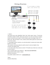
The Power Harness.
• To power the system connect
the power (RED) 12V+ wire to
ignition power and the ground
(BLACK) wire to chassis ground.
• These are the only wires
needed to power the entire
system and all the cameras.
Each camera can be seen at
any time by simply pressing
the power button and using
the V1/2 button to toggle.
• The three positive trigger wires
(WHITE-CH1, BROWNCH2,
BLUE-CH3) each represent one
channel and will turn on their
channel when the trigger wire
is energized with 12V.
• "Camera 3" is the designated
backup channel. To have the
the backup camera come on
when you go into reverse, con-
nect the BLUE wire to reverse
power (or any power source
that comes on only in reverse).
• The other channels can simi-
larly be triggered (i.e. side cam-
eras can be triggered by the turn
signals etc.)
• To automatically have camera
and monitor turn ON when vehi-
cle activates, simply twist BLUE
positive trigger 12V+ to Red
Power line 12V+ and wire to ig-
nition power.
Note: This setup will disable
the menu in channel 3. To
access the menu simply move
to channel 1 or 2 and all the
changes will apply to channel
3.
Note: When the blue wire is
active it will have precedence
over the other triggers.
Therefore, if you wish to use
multiple triggers, do not
attach the blue trigger to
constant power.

11
Reverse With Confidence
™
Wiring Camera & Monitor
• Audio: There is audio on
channels 2 and 3. On channel 3
the blue trigger wire must be
energized (12V) to activate the
audio. On channel 2 the audio
is always on.
• Grid-lines: The grid-lines are
also carried through the blue
wire. To use the grid-lines for
reversing, connect the blue
wire to a reverse power.
• There is a built-in voltage
regulator for our systems which
can handle 12-24 volts. Real
consumption is 10 to 30 Volts.
Note: The camera and
monitor can always be
activated by manually
pushing the power button on
monitor. This is in addition to
utilizing the positive triggers.
Note: If connecting power
directly to battery, the camera
is always ON and therefore can
drain battery. Therefore it is
recommended to connect
power to an ignition switched
accessory power source.

REAR VIEW SAFETY
12
Installation Diagram
Figure 1.1
Figure 1.2
Figure 1.3
Figure 1.4
Connection of U
Bracket
Connection of
Flushmount Bracket

13
Reverse With Confidence
™
Installing the Monitor
1. DC12V-24V
2. Ground
3. Port #3 (blue)
4. Port #2 (brown)
5. Port #1 (white)
1
2
3
4
5
3 Amp Fuse
Monitor
Power Harness
66ft Extension Cable
Camera
Optional
Camera
Available

14
Monitor Operation
REAR VIEW SAFETY
MENU
REV
V1/V2
▼
▼
POWER
ON / OFF
MENU/
SELECTION
BUTTON
CAMERA
SELECTION
DOWN
ARROW
UP
ARROW
ROTATE
IMAGE
(Back/Exit
when in
Menu Mode)
!!
!!
!!
!!
!!
!!
!!
!!
!!
!!
• Brightness, Contrast, Saturation, Sharpness: adjust image properties
• Turn: Toggle between mirror/normal image on each individual channel
• Day/Night: Toggle between back-lit buttons and auto dimming
• Name: Change name of each individual channel
• Trigger Source: Toggle channel destination for each trigger
• Trigger Delay: Adjust time delay on each trigger
• Distance Grid: Toggle which channel distance grid lines will display on
• Grid Position: Adjust grid lines
• Auto Power: On: Monitor will automatically turn on when powered. Off: Monitor will
only turn on when triggered. Auto: Monitor will follow previous state.
• Reset: Reset settings to factory default

15
Reverse With Confidence
™
Splitting & Splicing
Installing sun shield: Put shade cover on
the display. Installing back cover: Put the
monitor with shade cover in the back cover
(only for embedded monitor)
Splitting back cover: Hold monitor with 2
hands and detach with fingers, as indicated
by arrows. (only for embedded monitor)
Splitting sun shield: Take the monitor with
the left hand and detach with right hand as
indicated by the white arrow. (see below)
1. Red - Power (+)
2. Yellow - Video
3. Green - Mirror / Normal Imaging
4. White - Audio
5. Black - Ground (-)
1.
2.
3.
4.
5.

REAR VIEW SAFETY
16
Positioning

17
Reverse With Confidence
™
table of contents
Monitor Dimensions
5.25”
7”
power
video select
down/up
menu
mirror/
normal
image
Power
On/Off
Menu/
Selection
Button
Camera
Selection
Down
Arrow
Up
Arrow
Rotation
Imager
(Exit in
Menu
Mode)

REAR VIEW SAFETY
18
Monitor Specifications
TFT LCD Digital Monitor
Screen Size 7”
Dot Resolution 800
H x 3 (RGB) x 480V
Display Format 16:9 / 500:1
Display Brightness 400cd/m
2
Viewing Angle U:50° / D:60° / R:70°
Video Input 3 channel
Video Source 1Vp-p, 75
Power Supply DC 12V-24V (+/- 10%)
Power Consumption 5W
Operating Temperature -30°C ~ +80° C
Video System Auto NTSC/PAL
Overall Dimensions 7”
L x 5.25”H x 1”D
Weight 400G
Impact Rating 5G
Dot Pitch 0.192
H x 0.1805V
Sync System Internal

19
Reverse With Confidence
™
table of contents
Camera Dimensions
3”
3.25”

REAR VIEW SAFETY
20
Camera Specifications
Camera 1/4” Sharp® Color CCD
Picture Elements 250,000 pixels
Gamma Correction
Image Sensor
r=0.45 to 1.0
600 TVL NTSC 769H x
494 V, PAL 752H x 582V
Lens 2.1mm
View Angle 130°
Sync System Internal Synchronization
Infrared distance 50 Feet (18 Infrared IR)
Usable Illumination 0 Lux (IR On)
Power Source DC 12V-24V (+/- 10%)
S/N Ratio More than 48dB
Electronic Iris 1/50, 1/60-1/100,000sec
Video Output 1Vp.p 75ohm
IR Switch Control ACDS Automatic Control
Impact Rating 20G Vibration/100G Shock
Operating Temperature
Storage Temperature
-40
°C~80°C
-40°C~60°C
/