According to UL508C, frequency converters supplied as of
May 9, 2013 shall be:
a. Provided with motor load and speed sensitivity
overload protection with thermal memory
retention (ETR function),
b. Provided with means to accept and act upon a
signal from a thermal sensor or switch imbedded
in the motor or from an external protection relay,
or
c. Marked to indicate that the equipment is not
incorporating internal overload protection for the
motor load and is intended to be used with
external or remote overload protection.
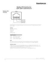
Danfoss VLT® frequency converters comply with UL508C
thermal memory retention requirements [UL508C par.
20.1.11(a)] as of the following software releases:
Drive series Type code SW version with ETR function
VLT® AutomationDrive FC 30x 6.81, Dec. 2012
VLT® AutomationDrive FC 322 2.03, Mar. 2013
VLT® AQUA FC 20x 2.03, Mar. 2013
VLT® HVAC FC 102 4.01, Mar. 2013
VLT® HVAC Basic FC 101 2.50, Apr. 2013
VLT® Refrigeration FC 103 1.20, Apr. 2013
VLT® Decentral Drive FCD 302 6.81, Dec. 2012
VLT® Decentral Drive FCD 300 1.58, May 2013
VLT® Drivemotor FCM 300 3.24, May 2013
VLT
® 280
0 VLT2800 3.23, May 2013
VLT® Micro FC 51 3.10, May 2013
For any drive series not mentioned above or for units
supplied with earlier software versions, ensure that:
- The frequency converter is configured to react on
input from a motor thermal
sensor or switch
[UL508C par 20.1.11 (b) and 56.7]. Refer to the
Design Guide for wiring and programming
information..
- The motor is equipped with an external over-
temperature protection
device [UL508C par
20.1.11 (c) and 56.7], or
- The motor circuit includes a separate overload
relay [UL508C par 56.6].
1.1.1 UL508C-Konformität
a) über last- und drehzahlabhängigen Motorüberlastschutz
mit thermischem Gedächtnis (ETR-Funktion) verfügen, b)
über Vorrichtungen zur Quittierung von und Reaktion auf
Signale eines in den Motor integrierten Thermosensors
oder -schalters oder eines externen Schutzrelais verfügen
oder c) entsprechend gekennzeichnet sein, wenn das Gerät
keinen internen Überlastschutz für die Motorlast besitzt
und mit externem oder ferngesteuertem Überlastschutz zu
betreiben ist. Danfoss VLT® Frequenzumrichter entsprechen
den Anforderungen hinsichtlich des thermische Gedächt-
nisses nach UL508C [UL508C Par. 20.1.11(a)] ab den
folgenden Software-Versionen:
Nach UL508C müssen ab dem 9. Mai 2013 gelieferte
Frequenzumrichter:
a. über last- und drehzahlabhängigen Motorüber-
lastschutz mit thermischem Gedächtnis (ETR-
Funktion) verfügen,
b. über Vorrichtungen zur Quittierung von und
Reaktion auf Signale eines in den Motor
integrierten Thermosensors oder -schalters oder
eines externen Schutzrelais verfügen oder
c. entsprechend gekennzeichnet sein, wenn das
Gerät keinen internen Überlastschutz für die
Motorlast besitzt und mit externem oder fernges-
teuertem Überlastschutz zu betreiben ist.
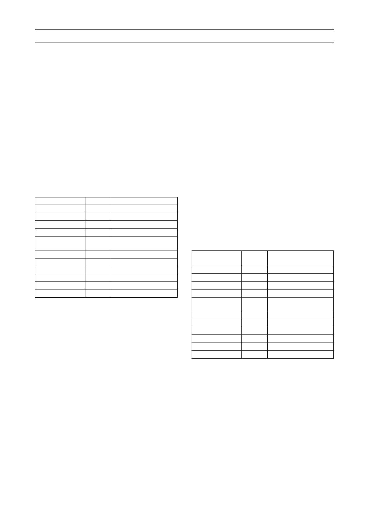
Danfoss VLT® Frequenzumrichter entsprechen den
Anforderungen hinsichtlich des thermische Gedächtnisses
nach UL508C [UL508C Par. 20.1.11(a)] ab den folgenden
Software-Versionen:
Umrichter-Baureihe Typencode SW-Version einschl. ETR-
Funktion
VLT® AutomationDrive FC 30x 6.81, Dec. 2012
VLT® AutomationDrive FC 322 2.03, Mar. 2013
VLT® AQUA FC 20x 2.03, Mar. 2013
VLT® HVAC FC 102 4.01, Mar. 2013
VLT® HVAC Basic FC 101 2.50, Apr. 2013
VLT® Refrigeration FC 103 1.20, Apr. 2013
VLT® Decentral Drive FCD 302 6.81, Dec. 2012
VLT® Decentral Drive FCD 300 1.58, May 2013
V
LT® Dr
ivemotor FCM 300 3.24, May 2013
VLT® 2800 VLT2800 3.23, May 2013
VLT® Micro FC 51 3.10, May 2013
Achten Sie bei Umrichter-Baureihen, die nicht in der
Tabelle aufgeführt sind, sowie bei Geräten, die mit
früheren Software-Versionen ausgestattet sind, auf
Folgendes:
- Der Frequenzumrichter ist so konfiguriert, dass er
auf Signal ein
es Motor-Thermosensors oder -
schalters reagiert [UL508C Par. 20.1.11 (b) und
56.7]. Siehe das Projektierungshandbuch für
Informationen zu Verdrahtung und Program-
mierung.
- Der Motor ist mit einer externen Überhitzungs-
schutzvorrichtung ausgestattet [UL508C Par.
20.1.11
(c) und 56.7], oder
- der Motorstromkreis enthält ein separates
Überlastrelais. [UL508C Par. 56.
6].