River of Goods 19549 Installation guide
- Category
- Household fans
- Type
- Installation guide

MODEL NO.: 19548/19549
Installation Guide
MODEL NO.:
19548/19549
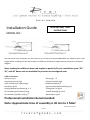
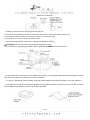
You may install your ceiling fan as a flush mount, or you may use the provided down rod. Measure your room
height before installing the fan and consider the different installation height options indicated in the above
diagram.
Note: Looking for additional down rod lengths to perfectly fit your installation space? 21”,
36”, and 48” down rods are available for purchase at riverofgoods.com
Table of Contents:
Safety tips Pg.2 Wiring Pg.7 -
8
Unpacking your fan Pg.3 Canopy Assembly Pg.8
Tools and material required Pg.4 Blade Assembly Pg.9
Outlet Box Pg.4-5 Light Kit and Shade Assembly Pg.10
Hanging Bracket Installation Pg.4 -
5
Testing Your Fan Pg.11
Fan Assembly (Flush Mount) Pg.6 Trouble Shooting Pg.11-
12
Fan Assembly (w/down rod) Pg.
7
Maintenance Pg.12
Professional Installation Recommended
Note: Approximate time of assembly is 30 min to 1 hour
PRINTED IN CHINA
PAGE 1
READ AND SAVE THESE
INSTRUCTIONS

MODEL
N
O.
:19548/19549
PAGE
2
SAFETY TIPS
WARNING: To reduce the risk of electrical shock, turn off the electricity to the fan at the main fuse box or circuit
panel before you begin the fan installation or before servicing the fan or installing accessories.
1. READ ALL INSTRUCTIONS AND SAFETY INFORMATION CAREFULLY BEFORE INSTALLING YOUR FAN AND SAVE THESE
INSTRUCTIONS.
CAUTION: To avoid personal injury, the use of gloves may be necessary while handling fan parts with sharp edges.
1.
Make sure all electrical connections comply with Local Codes or Ordinances, the National Electrical Code, and ANSI/NFPA
70-1999. If you are unfamiliar with electrical wiring or if the house/building wires are different colors than those referred to in the
instruction please use a qualified electrician.
2.
Make sure you have a location selected for your fan that allows clear space for the blades to rotate and at least seven (7) feet
(2.13 meters) of clearance between the floor and the fan blade tips. The fan should be mounted so that the tips of the blades are at
least thirty (30) inches (76 centimeters) from walls or other upright structures.
3.
The outlet box and ceiling support joist used must be securely mounted, and capable of supporting at least 50 Pounds (23
kilograms). The outlet box must be supported directly by the building structure. Make sure the electrical box that will hold the ceiling
fan is fan-rated. There should be an inscription on the box indicating it.
WARNING: To reduce the risk of fire, electrical shock, or personal injury, mount to the outlet box marked “Acceptable for Fan
Support,” and use the mounting screws provided with the outlet box. Most outlet boxes commonly used for the support of lighting
fixtures are not acceptable for fan support and may need to be replaced. Consult a qualified electrician if in doubt.
WARNING: To reduce the risk of fire, electrical shock, or personal injury, wire connectors provided with this fan are designed to
accept only one 12 gauge house wire and two lead wires from the fan. If your house wire is larger than 12 gauge or there is more than
one house wire to connect to the two fan lead wires, consult an electrician for the proper size wire connectors to use.
4.
After making electrical connections, spliced conductors should be turned upward and pushed carefully up into the outlet box. The
wires should be spread apart with the grounded conductor and the equipment-grounding conductor on opposite sides of the outlet box.
WARNING: To reduce the risk of electrical shock, fire and to prevent humming noise do not use this fan with any solid state speed
control device or control fan speed with a full range dimmer switch. Using a full range dimmer switch to control fan speed will cause a
loud humming noise from fan.
5.
Do not operate the reverse switch until fan has come to a complete stop.
6.
Do not insert anything between the fan blades while they are rotating.
WARNING: To reduce the risk of personal Injury, do not bend the blade brackets when installing the brackets, balancing the blades,
or cleaning the fan. Do not insert foreign objects in between rotating fan blades.
WARNING: To avoid personal injury or damage to the fan and other items, be cautious when working around or
cleaning the fan.
7.
Do not use water or detergents when cleaning the fan or fan blades. A dry dust cloth or lightly dampened
cloth will be suitable for most cleaning.
WARNING: To reduce the risk of personal injury, use only parts provided with this fan. The use of parts OTHER than those
provided with this fan will void the warranty.
NOTE: The important safety precautions and instructions appearing in the manual are not meant to cover all
possible conditions and situations that may occur. It must be understood that common sense and caution are
necessary factors in the installation and operation of this fan.

MODEL
N
O.
:19548/19549
PAGE
3
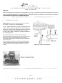
1. Unpacking Your Fan.
Carefully open the packaging. Remove items from
styrofoam inserts. Remove motor housing and place on
carpet or styrofoam to avoid damage to finish. Do not
discard fan carton or styrofoam inserts should this fan
need to be returned for repairs.
Check against parts inventory that all parts have been included.
2. Parts Inventory.
Canopy
Canopy Bracket
Down rod
6”
Down rod
cover
Remote and Receiver
w/battery
Motor housing
Light Kit
Blade arms
(5)
Blades (5)
Shade
or
Hardware
bag (16 sets
for Blades
assembly)
Balancing kit
Hardware bag
Required Bulbs (Not Included):
Light kit – E12, Type B, 6W (LED-2700K-Dimmable) x 3
Alternative bulb usage: CFL or Incandescent Bulbs may be used. Ensure the Max. Wattage indicated on the socket labels is not
exceeded, and verify the bulbs do not get in contact with any metal part of the fan components (shade or motor housing)
WARNING: DO NOT EXCEED INDICATED BULB WATTAGE
Note for Stained Glass shade items: the stained glass shade has been protected with mineral oil as part of the finishing process. Please
use a soft dry cloth to remove any excess oil.

MODEL
N
O.
:19548/19549
PAGE
4
3. Tools Required
•Step ladder
•Pliers
•Screw driver flat head and phillip
•Electrical tape
•Circuit tester
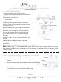
4. Installation Preparation
To prevent personal injury and damage, ensure that
the hanging location allows the blade a clearance
of 7ft.(2.13m) from the floor and 30in.(76cm) from
any wall or obstruction.
The fan is suitable for room sizes up to 400 square
feet (37.2square meters).
This fan can be mounted with a down rod
on a normal or vaulted ceiling. Down rod is
included, 6” length.
This fan can also be mounted using flush mount
installation as seeing in diagram.
5. Hanging Bracket Installation.
Turn off circuit breakers to current fixture from breaker panel
and be sure operating light switch is turned to the OFF position.
WARNING: Failure to disconnect power supply prior to
installation may result in serious injury and fire hazard.
Remove existing fixture.
WARNING: When using an existing outlet box, be sure the
outlet box is securely attached to the building structure and can
support the full weight of the fan. Ensure the outlet box is clearly
marked “Suitable for Fan Support". If not, it must be replaced
with an approved outlet box. Failure to do so can result in
serious injury.

MODEL
NO: 19548/19549
PAGE
5
CAUTION: Be sure outlet box is grounded properly and that a
ground wire (green or bare) is present.
Partially loosen screws in slotted holes of canopy. Remove
the other 2 screws (along with the star washers) -save for
later use. Twist canopy to remove hanging bracket.
Install hanging bracket to outlet box using original screws,
spring washers and flat washers provided with new or
original outlet box. If installing on a vaulted ceiling, face
opening of Hanging Bracket towards high point of ceiling.
Arrange electrical wiring around the back of the hanging
bracket and away from the hanging bracket opening.
CAUTION: It is very important that you use the proper
hardware when installing the hanging bracket as this will support
the fan.
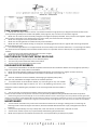
ELECTRICAL OUTLET BOX
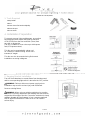
WARNING: It is recommended to contact a qualified electrician to replace the outlet box if not suitable for ceiling fans
1. If there is an existing outlet box, ensure it is clearly marked “Suitable For Fan Support”.
If not, it must be replaced with an approved one.
2. Secure the outlet box (or make sure the existing box is secured) directly to the
building structure. Use appropriate fasteners and building materials. Wood joist
and outlet box must be able to support a minimum of 50 pounds.
3. Figure 1, 2 and 3 are examples of different ways to mount the outlet box in
different situations.
4. To hang the fan in locations where no ceiling joists is available. A hanger support
bar may be required (Fig. 4)

MODEL
NO: 19548/19549
PAGE
6
6. Flush Mount Assembly. Go to step 7 if assembling with down rod.
• Remove round rubber ring from the Canopy
• Thread the electrical wires through the canopy.
• Remove every other screw on the motor housing
total of 3 screws.
WARNING – Ensure you only remove every
other screw, others must remain firmly tightened.
• Attach the canopy to the motor housing securely
with the 3 screws previously removed. Tighten firmly.
• Continue to step 8 for wiring.

MODEL
NO: 19548/19549
PAGE
7
7. Fan Assembly with Down Rod
Remove Pin and Clip from down rod (if you have not already done so).
Slide the Down rod through the canopy, and the Down rod cover as
shown.
Thread the electrical wires through down rod and pull extra wire slack
from the upper end of the down rod.
Tip: Apply small piece of electrical tape to the ends of the electrical
wires to keep them together when threading them through the
down rod.
Loosen the Yoke set screw. Place the Down rod into the Motor housing
yoke and re-insert pin and clip that were previously removed. Tighten
Yoke the set screw securely.
With the Hanging bracket secured to the outlet box and able to support
the fan, you are now ready to hang your fan. Grab the fan firmly with
two hands. Slide down the rod ball through the opening in the hanging
bracket and let hanging ball rest on the hanging bracket. Turn the hanging
ball slot until it lines up with the hanging bracket tab.
8. Wiring with Remote Receiver
IMPORTANT: you must set the ceiling fan manual pull chain switch to
HIGH speed and light kit to ON position to ensure proper operation of the
remote control.
WARNING: Failure to disconnect power supply prior to the installation may result in serious injury and fire
hazard.
CODE SWITCH – see next page diagram
2. Codes are set by pushing Dip switches up or down. It is imperative that the code used for both transmitter and
receiver is exactly the same, otherwise the remote controller will not work. Please note the code switch will enable
you to operate a second remote controller independently. For example, if you have two ceiling fans with 2 remote
control units, set 2 different codes for each set of transmitter/receivers. This means you can operate each ceiling
fan independently.
3. Your remote control is ready for use after the battery installation (9Volts battery included).
CAUTION: The battery will weaken with age and should be replaced before leaking takes place as this will
damage the transmitter. Dispose of used battery properly, keep the battery out of reach of children. To reduce the
risk of fire or injury, do not use this product in conjunction with any variable (rheostat) wall control.

MODEL
NO: 19548/19549
PAGE
8
4. Install the receiver into the Hanging bracket of the fan.
This unit is to be used for the control of ceiling fan and in an AC120V 60Hz power supply only.
Do not install in damp locations or immerse in water. For indoor use only.
Do not pull on or cut the receiver wire leads shorter.
5. Proceed making the wire connections following this diagram carefully.
CAUTION: Incorrect wire connection would damage the receiver.
Be sure outlet box is properly grounded or that a ground wire (GREEN or bare) is present.
6. Ensure all the wire connectors are securing the wires firmly. It is recommended to apply electrical tape covering
the connector and wires to further secure the connections.
7. The splices, after being carefully made, should be turned upward and pushed carefully up into the outlet box.
8. Then slide the Canopy up covering the Hanging bracket and Remote Receiver as shown. Secure the Canopy to
the Hanging Bracket with the screws and washers provided.

PAGE
9
MODEL
N
O.
: 19548/19549
Important:
Make sure all electrical connections comply with Local Codes or Ordinances and the National Electrical Code. If
you are unfamiliar with electrical wiring, or if the house/building wires are different colors than those referred to
in the instructions, please use a qualified electrician.
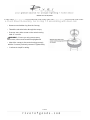
9. Blade Assembly.
Time Saver: Washers for blade screws can be set on
each blade screw prior to installing blades.
Locate 15 blade attachment screws and washers in one
of the hardware packs. Hold blade arm up to blade and
align holes. Insert 3 blade attachment screws (along with
washers) with fingers first, and then tighten screws
securely with a philip screwdriver. Repeat procedure for
the remaining blades.
Remove the Blade arm screws and lock washers
from the fan Motor housing and set aside. Then, remove
the Motor shipping pads and discard (see figure to
identify the pads). Align the Blade arm holes with motor
screw holes and
attach the blade arm with lock washers and blade arm
screws. Before securing screws completely, repeat the
procedure with all remaining blade arms. Secure all
screws.

MODEL
N
O.
: 19548/19549
PAGE
10
10. Light Kit Assembly.
1.
Remove the three screws from the Light kit.
2.
Plug the connectors from the Light kit to the connectors
from the Switch housing.
Please note the correct wiring is:
•White to White
• Black to Blue
3.
Gently push the connectors into switch housing and
align the holes in the Light kit with holes in the Switch
housing. Secure the light kit with the 3 screws that were
previously removed.
Attach the Shade to the Light kit using the Finial you will
find installed on the Light kit pipe. Insert the pull chains
through the holes on shade, and then attach the pull
chain Fobs. Do not over tighten the finial.
Since this fan includes a Remote Controller you may
decide not to install the Pull chains and Fob through
the shade.
Install: E12, Type B, 6W (LED-2700K-Dimmable) x 3 (Not
Included)
Important: When replacing the bulb(s), please allow
bulb(s) and glass shade(s) to cool down before
touching them.
WARNING: DO NOT EXCEED INDICATED BULB WATTAGE
Alternative bulbs usage: CFL or Incandescent bulbs may be used. Ensure the Max. Wattage indicated on the socket
labels is not exceeded, and verify the bulbs do not get in contact with any metal part of the fan components (shade
or motor housing)
Tiered Shades Assembly if included with your Fan
1. Install the Shade A on the Light kit using the finial or nut provided.
2. Then using the nut or Final installed on the Light kit pipe attach the
Shade A.
3. Remove the three screws from the Shade A and install the Shade B
with the same screws. A the same time pass pull chains through
the Shade B.
Note: Since this fan includes a Remote Controller you may decide
not to install the Pull chains and Fob through the shade.

MODEL
N
O.
: 19548/19549
PAGE
11
11. Testing Your Fan
It is recommended that you test the fan before finalizing installation. Restore
power from circuit box and light switch (if applicable). Test the fan speeds
from the Remote controller. Start at the OFF position (no blade movement)
and
continue testing the LOW, MED and HI speeds. Every time you press any
key the red LED witness light will turn ON at the top of the controller.
If the red LED witness light does not turn on when pressing any key, replace
the 9 Volts battery.
The Remote controller will only operate both the Motor housing and Light kit
lights simultaneously.
If the remote receiver is NOT installed in your fan, you will be able to operate
the Motor housing and Light kit lights independently from the Pull chains. The
first pull will turn on only the UPPER lights in the lighting housing. The
second pull will
turn on only the LOWER lights in the light kit. The third pull
will turn on ALL of the lights (upper and lower), and the fourth pull will turn all
of the lights OFF again.
The reverse fan switch may only be operated by the switch located in Switch
housing, not from the Remote controller. Set the reverse switch to recirculate
air,
depending on the season.
TROUBLE SHOOTING
FAN‐LIGHTS DO NOT START
1. Check all fuses or circuit breakers.
2. Turn off electrical power and check all wire connections
• From the house electrical power line to the Receiver (Black and White wires)
• From the Receiver to the Fan wires (Black, White and Blue wires)
• From the Fan to the Light Kit (two wires)
3. Fan Reverse switch is up or down, not in the middle, see image
4. Make sure you have set the Dip switches on the Remote and Receiver to the same numbers, see diagram
5. IMPORTANT: you must set the ceiling fan to:
• Pull Chain switch to HIGH speed and,
• Light Kit to ON position to ensure proper operation of the remote control
* In order to accomplish this you may have to pull the chains AND push the buttons on the
Remote every time until finding the right setting
6. Wire the ceiling fan without the Receiver to determine if the receiver is faulty, that is to disconnect the Receiver and following the
wiring instructions connect the house electrical power line directly to the Fan
• If the Fan and Lights work properly, then the Receiver and Remote are faulty. ROG can provide a replacement Receiver
and Remote
Bulbs
Note: You may use equivalent wattage CFL or incandescent bulbs
1. Ensure that the bulbs are securely seated into the socket(s)
2. For included or recommended bulb usage, please refer to “Bulb Specifications” in Pg. 3 of these Assembly
Instructions

MODEL
N
O.
: 19548/19549
PAGE
12
FAN FOUND NOISY
1.
Always take a few days" break in" time for any new fan at medium or high speed. Try to diagnose the exact location of the
noise by listening carefully from several sides (blades, motor, light kit, etc). Fan noise can come from a light kit.
2.
Make sure all screws in the fan assembly and light kit are tight and properly threaded. If not, back out and re tighten. Tighten
these screws at least twice a year because they may loosen slowly over time and cause clicking noise.
3.
Make sure the light kit is securely fastened to the fan.
4.
Make sure mounting bracket is installed securely to the outlet box.
5.
Make sure wire nuts in switch housing or canopy are not rattling against each other or against wall of housing. Wrap with
electrical tape if necessary.
6.
Use of standard light dimmer or unapproved wall control will always cause harmonic distortions, or a humming noise. Many
fan motors do not work quietly with solid‐state variable controls. If a quiet wall control is desired, use only approved wall
controls.
7.
Assure that the screws fastening blade holders to motor are tight
8.
Make sure all light bulbs are fully screwed in.
FAN TURNS BUT DOES NOT MOVE MUCH AIR
1. The fan may be running in reverse, so air is directed upward.
2. The room may contain items that obstruct the airflow.
3. The fan may be too small for the size of the room.
FAN SHAKES OR WOBBLES
1.
A small amount of wobble is considered acceptable and should not be considered a defect. Use of any light kit, especially a
large 4 or 5 light kit, will usually induce some wobble.
2.
Make sure Hanging bracket is tight at the outlet box/ceiling with no movement at all. Tighten screws if necessary.
3.
Make sure all screws holding the blades to the blade arm and blade arm to motor are
tight.
4.
Some fan movement is normal. However, interchanging an adjacent (side by side)
blade pair may redistribute the weight and result in smoother operation.
5.
If the above does not eliminate the wobble, clip a balancing kit on any one of blade
about
the middle of blade edge. Let the fan run. If it is still wobbling, stop the fan, and
change the
location. Repeating this procedure on the remaining blades until the wobble is
removed.
6.
You can also look up at the fan from below, make sure that none of the blade holders
are bent so that a blade is out of position. Correction may be made by GENTLY bending the blade holder back into position.
7.
Blade tracking may be checked simply by use of a household yardstick as shown in below Figure. Place the yardstick vertically
against the
ceiling and even with the outside leading edge of a blade. Note the distance of the edge of a blade same as others. Turn the blade slowly by hand
to check the remaining blades. If a blade is in an alignment, the blade holder may be gently bent up or
down to be in line with the other blades.
MAINTENANCE
1.
The fan natural movements may cause some connections to work loose. A clicking or rattling noise is a certain sign of
loosening screws. Check the support connections, brackets and blade attachment twice a year, and tighten all screws as
necessary.
2.
Clean your fan periodically. Use only a damp cloth, never use solvents, and dust with a soft cloth or brush.
3.
You will never need to oil your fan, its permanently sealed bearing will prevent noise.
4.
Make sure the power is turned off at the main fuse or circuit panel before you attempt any repairs.
-
 1
1
-
 2
2
-
 3
3
-
 4
4
-
 5
5
-
 6
6
-
 7
7
-
 8
8
-
 9
9
-
 10
10
-
 11
11
-
 12
12


River of Goods 19549 Installation guide
- Category
- Household fans
- Type
- Installation guide
Ask a question and I''ll find the answer in the document
Finding information in a document is now easier with AI
Related papers
-
River of Goods 16555s FAQ
-
River of Goods 20623 Operating instructions
-
River of Goods 20609 User manual
-
-
River of Goods 20683 User manual
-
-
-
-
-
Other documents
-
Trend TT80096 User manual
-
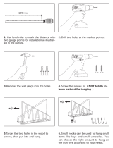 SRIWATANA Letter Mail Holder Wall Mount, Rustic Bill Mail Organizer Hanging Key Holder Installation guide
-
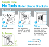 Redi Shade 3251514HD Installation guide
-
Trend BA6002 User manual
-
Trend BA6013 User manual
-
Trend Lighting BA6003 User manual
-
Dale Tiffany 7908/816A Operating instructions
-
-
VISUAL COMFORT KW3686 User manual
-
AireRyder FN433 series Instructions For Installation And Use Manual

