Page is loading ...

DESCRIPTION
The air motor is a precision built rotary
vane type motor. The vanes take up
their own wear and will last 5,000 –
15,000 hours depending upon speed,
method of oiling, operating pressure,
and the precautions taken in
maintaining the motor. The type of shaft
seal used does not lend itself to
operating pressures above 100 psi.
Allowing excess moisture or foreign
particles from the air line to enter the
motor will reduce operating life.
INSTALLATION
First install a moisture trap and filter in
the air line ahead of motor. For
efficiency of output and control of speed
use air lines or hose the same size as,
or the next pipe size larger than, the
intake port of the motor.
OPERATION
The stalled or starting torque is less
than the running torque and will vary
depending on the position at which the
vanes stop in relation to the air intake
port. Operate motor well below available
line pressure so that full line pressure
can be called upon for overloads on
motor. The speed is regulated by the air
valve (8). If the duty is continuous or
speed is high, use an automatic air line
oiler set to feed 1–3 drops per minute.
The bearings will receive oil from the
rotor chamber during automatic oiling.
Use SAE No. 10 non-detergent oil.
Lubrication is necessary for the
bearings, shaft seals, and rust
prevention. Excessive moisture in the air
line can cause rust formation in motor
and might also cause ice to form on
muffler due to expansion of air through
the motor. The moisture problem can be
corrected by installing a moisture
separator in the line and also by
installing an aftercooler between the
compressor and air receiver.
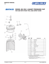
1 20-1076 SET SCREW ................................... 4
2 20-3344 SET SCREW ................................... 2
3 20-6781 PIN ................................................ 8
4 31-9 COUPLING ..................................... 1
5 31-291 ADAPTER ....................................... 1
6 31-292 SHAFT ........................................... 1
7 57-13-1 NIPPLE .......................................... 1
8 73-159 AIR VALVE ..................................... 1
9 83-1527 MUFFLER ....................................... 1
10 83-2815 AIR MOTOR, 1 H.P. (31-296) ............... 1
83-2798 AIR MOTOR, 1/2 H.P. (31-295) ............
*
11 149-844 BLADES ......................................... 8
12 HUB .............................................. 2
13 149-851 PADDLE ASSEMBLY ......................... 2
*Obsolete—for reference only. Only available in 149-851.
ITEM PART
NO. NO. DESCRIPTION QTY.
PARTS LIST
When ordering, please specify Part No.
!
IMPORTANT
Read and following all instructions and safety precautions listed on Page 2 before
using equipment. Retain for future reference.
10
8
7
6
13
4
1
5
1
9
Includes Item Nos.
2, 3, 11 & 12.
MODEL 31-296 (1 H.P.) AGITATOR
MODEL 31-295 (1/2 H.P.) OBSOLETE—FOR REFERENCE ONLY
77-2055-R9 (4/2018) 1 / 4 www.carlisleft.com
EN
SERVICE MANUAL

LOCK OUT / TAG-OUT
Failure to de-energize, disconnect, lock out and tag-out all power
sources before performing equipment maintenance could cause
serious injury or death.
OPERATOR TRAINING
All personnel must be trained before operating finishing
equipment.
EQUIPMENT MISUSE HAZARD
Equipment misuse can cause the equipment to rupture,
malfunction, or start unexpectedly and result in serious injury.
PROJECTILE HAZARD
You may be injured by venting liquids or gases that are released
under pressure, or flying debris.
PINCH POINT HAZARD
Moving parts can crush and cut. Pinch points are basically any
areas where there are moving parts.
INSPECT THE EQUIPMENT DAILY
Inspect the equipment for worn or broken parts on a daily basis.
Do not operate the equipment if you are uncertain about its
condition.
In this part sheet, the words WARNING, CAUTION and NOTE are used to
emphasize important safety information as follows:
Hazards or unsafe practices which
could result in minor personal injury,
product or property damage.
!
CAUTION
Hazards or unsafe practices which
could result in severe personal
injury, death or substantial property
damage.
!
WARNING
Important installation, operation or
maintenance information.
NOTE
Read the following warnings before using this equipment.
READ THE MANUAL
Before operating finishing equipment, read and understand all
safety, operation and maintenance information provided in the
operation manual.
WEAR SAFETY GLASSES
Failure to wear safety glasses with side shields could result in
serious eye injury or blindness.
NEVER MODIFY THE EQUIPMENT
Do not modify the equipment unless the manufacturer provides
written approval.
IT IS THE RESPONSIBILITY OF THE EMPLOYER TO PROVIDE THIS INFORMATION TO THE OPERATOR OF THE EQUIPMENT.
FOR FURTHER SAFETY INFORMATION REGARDING THIS EQUIPMENT, SEE THE GENERAL EQUIPMENT SAFETY BOOKLET (77-5300).
KNOW WHERE AND HOW TO SHUT OFF THE EQUIPMENT
IN CASE OF AN EMERGENCY
PRESSURE RELIEF PROCEDURE
Always follow the pressure relief procedure in the equipment
instruction manual.
NOISE HAZARD
You may be injured by loud noise. Hearing protection may be
required when using this equipment.
STATIC CHARGE
Fluid may develop a static charge that must be dissipated through
proper grounding of the equipment, objects to be sprayed and all
other electrically conductive objects in the dispensing area. Improper
grounding or sparks can cause a hazardous condition and result in
fire, explosion or electric shock and other serious injury.
PROP 65 WARNING
WARNING: This product contains chemicals known to the
State of California to cause cancer and birth defects or other
reproductive harm.
WEAR RESPIRATOR
Toxic fumes can cause serious injury or death if inhaled.
Wear a respirator as recommended by the fluid and solvent
manufacturer’s Safety Data Sheet.
TOXIC FLUID & FUMES
Hazardous fluid or toxic fumes can cause serious injury or death if
splashed in the eyes or on the skin, inhaled, injected or
swallowed. LEARN and KNOW the specific hazards or the fluids
you are using.
KEEP EQUIPMENT GUARDS IN PLACE
Do not operate the equipment if the safety devices have been
removed.
!
WARNING
AUTOMATIC EQUIPMENT
Automatic equipment may start suddenly without warning.
FIRE AND EXPLOSION HAZARD
Improper equipment grounding, poor ventilation, open flame or
sparks can cause a hazardous condition and result in fire or
explosion and serious injury.
MEDICAL ALERT
Any injury caused by high pressure liquid can be serious. If you
are injured or even suspect an injury:
• Go to an emergency room immediately.
• Tell the doctor you suspect an injection injury.
• Show the doctor this medical information or the medical alert
card provided with your airless spray equipment.
• Tell the doctor what kind of fluid you were spraying or
dispensing.
GET IMMEDIATE MEDICAL ATTENTION
To prevent contact with the fluid, please note the following:
• Never point the gun/valve at anyone or any part of the body.
• Never put hand or fingers over the spray tip.
• Never attempt to stop or deflect fluid leaks with your hand,
body, glove or rag.
• Always have the tip guard on the spray gun before spraying.
• Always ensure that the gun trigger safety operates before
spraying.
EN
77-2055-R9 (4/2018)2 / 4www.carlisleft.com

Binks MODEL 83-2815 AIR MOTOR ASSEMBLY
(MODEL 83-2798 OBSOLETE—FOR REFERENCE ONLY)
SPEED
The speed of the air motor is regulated by the air
adjusting valve, part number 73-159 (see page 1).
The speed of the propeller shaft is determined by
the fluid, but it should never exceed 3,000 RPM.
AIR SUPPLY
The air supply to the motor should be 60 PSI,
minimum, for best results.
LUBRICATION—AIR MOTOR
The bearings are pre-lubricated and sealed. However,
every 100 hours insert a few drops of SAE 10 non-
detergent oil into the air inlet to lubricate the vanes
and housing surfaces.
1 QS-181*
▲
GASKET ......................................... 1
2 37-89 ROTOR (83-2798) ............................. 1
3 37-90*
▲
OIL SEAL ....................................... 1
4 37-91*
▲
BEARING ....................................... 2
5 37-92* VANE (83-2798) ................................ 4
6 37-93 BODY (83-2798) ............................... 1
7 37-96 END CAP ........................................ 1
8 37-337*
▲
GASKET, END CAP .......................... 2
9 37-412 PLATE, DEAD END .......................... 1
10 37-413 PLATE, DRIVE END ......................... 1
11 37-415 FILLISTER HEAD SCREW ................ 12
12 37-482 ROTOR (83-2815) ............................. 1
13 37-484
▲
VANE (83-2815) ................................ 4
14 37-1045 BODY (83-2815) ............................... 1
ITEM PART
NO. NO. DESCRIPTION QTY.
*
Repair Kit Parts for 83-2798. Order 6-183.
*
Also available in Repair Kit 6-183. Please order separately.
▲ Also available in Repair Kit 6-197. Please order separately.
PARTS LIST
When ordering, please specify Part No.
8
10
12
2
3
9
11
7
1
4
13
5
6
14
EN
77-2055-R9 (4/2018) 3 / 4 www.carlisleft.com

EN
77-2055-R9 (4/2018)4 / 4www.carlisleft.com
WARRANTY POLICY
This product is covered by Carlisle Fluid Technologies’ materials and workmanship limited warranty.
The use of any parts or accessories, from a source other than Carlisle Fluid Technologies,
will void all warranties. Failure to reasonably follow any maintenance guidance provided
may invalidate any warranty.
For specic warranty information please contact Carlisle Fluid Technologies.
For technical assistance or to locate an authorized distributor,
contact one of our international sales and customer support locations.
Region Industrial/Automotive Automotive Renishing
Americas
Tel: 1-800-992-4657 Tel: 1-800-445-3988
Fax: 1-888-246-5732 Fax: 1-800-445-6643
Europe, Africa,
Middle East, India
Tel: +44 (0)1202 571 111
Fax: +44 (0)1202 573 488
China
Tel: +8621-3373 0108
Fax: +8621-3373 0308
Japan
Tel: +81 45 785 6421
Fax: +81 45 785 6517
Australia
Tel: +61 (0) 2 8525 7555
Fax: +61 (0) 2 8525 7575
Carlisle Fluid Technologies is a global leader in innovative nishing technologies.
Carlisle Fluid Technologies reserves the right to modify equipment specications without prior notice.
DeVilbiss
®
, Ransburg
®
, ms
®
, BGK
®
, and Binks
®
are registered trademarks of Carlisle Fluid Technologies, Inc.
©2018 Carlisle Fluid Technologies, Inc.
All rights reserved.
For the latest information about our products, visit www.carlisleft.com
/