
1
M965890 Rev. 1.2 (9/19)
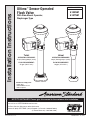
Installation Instructions
Ultima
™
Sensor-Operated
Flush Valve
With Side-Mount Operator,
Diaphragm-Type
Certied to comply with:
• ASSE 1037
• ANSI/ASME A112.19.2
• ADA Compliant
NOTE TO INSTALLER: Please give this manual to the customer after installation.
To learn more about American Standard Products visit our website at: www.americanstandard-us.com
or e-mail us at: CR[email protected]
For Parts, Service, Warranty or other Assistance,
please call (844) CRT-TEAM / (844) 278-8326 (In Canada: 1-800-387-0369)
(In Toronto Area only: 1-905-306-1093)
© 2019 AS America Inc.
MODEL NUMBERS
6145SM
6147SM
Toilet Urinal
OPERATING PRESSURE:
25 psi (owing)-80 psi (static)
FLOW REQUIREMENT:
25 gpm (94.6 L/min.)
OPERATING PRESSURE:
20 psi (owing)-80 psi (static)
FLOW REQUIREMENT:
10 gpm (37.9 L/min.)

2
M965890 Rev. 1.2 (9/19)
Thank you for selecting American Standard...the benchmark of ne quality for over 100 years. To ensure
that your installation proceeds smoothly--please read these instructions carefully before you begin.
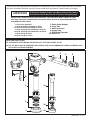
Remove the Flush Valve items from the carton. The illustration below shows all items
after they have been removed from the carton. Some items may be packaged partially
assembled to other items.
UNPACKING
All American Standard Products Are Water Tested At Our Factory.
Some Residual Water May Remain In The Valve During Shipping
CARE INSTRUCTIONS:
DO: CLEAN WITH CLEAR WATER. DRY WITH A SOFT COTTON FLANNEL CLOTH.
DO NOT: DO NOT CLEAN THE PRODUCT WITH SOAPS, ACID, POLISH, ABRASIVES, HARSH CLEANERS, OR A
CLOTH WITH A COARSE SURFACE.
9
10
1
5
6
7
8
2
3
4
2a
3a
4a
1. Flush Valve Assembly
2. Vacuum Breaker Assembly for Toilet
2a. Vacuum Breaker Assembly for Urinal
3. Spud Coupling Nut and Washers for Toilet
3a. Spud Coupling Nut and Washers for Urinal
4. Spud Flange for Toilet
4a. Spud Flange for Urinal
5. Sweat Solder Adapter
6. Cover Tube
7. Wall Escutcheon
8. Supply Stop
9. Side-Mount Operator
10. Wrench Kit

3
M965890 Rev. 1.2 (9/19)
1
2
3
4
5
6
7
8
10'
Right or Left Hand Installation
FOR 1-1/2" TOP
SPUD FIXTURES
-C-L-
SUPPLY
DN 19 mm
(1" I.P.S.
For 1"
Top Spud)
108 mm-133 mm
(4-1/4" to 5-1/4")
147 mm
(5-13/16")
253 mm
(9-15/16")
FINISHED WALL
38 mm-127 mm
(1-1/2-5")
-C-L-
*CRITICAL
LEVEL
152 mm
(6")
(Min.)
292 mm
(11-1/2")
6047.1x1
ROUGH-IN
DIMENSION
686 mm
(27")
6047.1x2
ROUGH-IN
DIMENSION
610 mm
(24")
6047.117
ROUGH-IN
DIMENSION
6047.1x2
765 mm
(30-1/8")
6047.117
689 mm
(27-1/8")
6047.1x1
371 mm
(14-5/8")
*Note: The Critical Line (-C-L-) on Vacuum Breaker
must typically be 6
" (152mm) minimum above fixture.
Consult Codes for details.
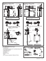
Roughing-in Dimensions
Fig.1
Fig.2
RECOMMENDED TOOLS; Fig. 2
1. Teon Tape
2. Flat Blade Screwdriver (For adjusting Supply Stop)
3. Adjustable Wrench
4. Tape Measure
5. Hacksaw
6. Tubing Cutter
7. File
8. For Sweat Connection; Solder and Torch
FINISHED WALL
FINISHED
FLOOR
57 mm Min.
(2-1/4")
371 mm
(14-5/8")
TYPICAL WATER CLOSET INSTALLATION:
AFWALL
™
TOILET SHOWN
295 mm
(11-1/2")
-C-L-
SEE ROUGH-IN
ABOVE
CRITICAL
LEVEL
108 mm, +/-13 mm
(4-3/4")(+/-1/2")
SUPPLY
DN 25 mm
(1" I.P.S.)
Right or Left Hand Installation
-C-L-
152 mm
(6)
(Min.)
*CRITICAL
LEVEL
SUPPLY
DN 19 mm
(3/4" I.P.S.
For 3/4"
Top Spud)
108 mm-133 mm
(4-1/4" to 5-1/4")
147 mm
(5-13/16")
295 mm
(11-1/2")
253 mm
(9-15/16")
FINISHED WALL
3/4" VACUUKM
BREAKER SHOWN
371 mm
(14-5/8")
38 mm-127 mm
(1-1/2-5")
-C-L-
*Note: The Critical Line (-C-L-) on Vacuum Breaker
must typically be 6
" (152mm) minimum above fixture.
Consult Codes for details.
FINISHED FLOOR
FINISHED WALL
371 mm
(14-5/8")
TYPICAL URINAL INSTALLATION: WASHBROOK URINAL SHOWN
295 mm
(11-1/2")
SEE ROUGH-IN
ABOVE
CRITICAL
LEVEL
-C-L-
SUPPLY
DN 20 mm
(3/4" I.P.S.)
108-133 mm
(4-1/4" to 5-1/4")
-C-L-
57 mm Min.
(2-1/4")
Roughing-in Dimensions
Fig.2

4
M965890 Rev. 1.2 (9/19)
CENTER LINE OF
FIXTURE SPUD
FINISHED WALL
FILE EDGES
SOLDER
ADAPTER
Fig. 3
ADAPTER
32mm
(1-1/4")
A
(A-B)=
B
C
CLEAN
3/4" TOP SPUD
1
2
3
4
Fig. 5
5a
5a
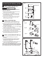
FLUSH VALVE INSTALLATION
1
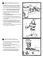
INSTALL SWEAT ADAPTER; Fig. 3
Note: Install Optional Sweat Adapter (Supplied) for
copper pipe supply line.
1. Measure the distance (A) from the nished wall to the
center of the inlet spud on the xture.
2. Cut the supply pipe 1-1/4" (A-B=C) shorter than the
measurement taken in Step 1. File any rough edges
off the end of the supply pipe.
3. Clean the end of the supply pipe. Push the threaded
Adapter until it is seated against the internal stop.
Sweat the Adapter to the pipe.
2
INSTALL COVER TUBE, WALL
ESCUTCHEON and STOP VALVE; Fig. 4
1. Measure from nished wall to rst thread of Adapter or
threaded supply pipe (dimension “X”). Cut COVER TUBE
(1) to length (X). Apply Teon Tape to the threaded end of
the Adapter or supply pipe.
2. Push WALL ESCUTCHEON (2) onto the COVER TUBE (1).
Slide both onto the SUPPLY PIPE (3).
3. Push the COVER TUBE (1) in to expose the threads of
the supply pipe. With a wrench thread the STOP VALVE
(4) onto the SUPPLY PIPE (3). Align and tighten.
4. Pull COVER TUBE (1) against STOP VALVE (4) and push
WALL ESCUTCHEON (2) against nished wall.
3
INSTALL VACUUM BREAKER TUBE; Fig. 5
1. Place the SPUD FLANGE (1) over the spud on
the Fixture.
2. Place FRICTION WASHER (3) and SEAL WASHER
(4) inside SPUD COUPLING NUT (2) and thread
onto Spud. Do not tighten fully.
3. Insert the VACUUM BREAKER TUBE (5) or (5a) into the
SPUD COUPLING NUT (2) and push it down.
Note: If cutting VACUUM BREAKER TUBE (5) to size, note
that Critical Line (C/L) on Vacuum Breaker must typically
be 6” (152mm) above xture. Consult Code for details.
CAUTION
Turn water supplies off before
beginning
Fig. 4a
Fig. 4b
Fig. 4c
1
1
4
2
3
Fig. 4
TEFLON TAPE
FINISHED WALL
X
X
2

5
M965890 Rev. 1.2 (9/19)
3
2
5
1
4
Fig. 6a
Fig. 6b
11
10
7
9
6
2
5
8
121mm, 13mm
(4-3/4")( 1/2")
+
–
+
–
4
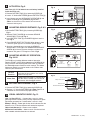
INSTALL FLUSH VALVE; Fig. 6a & 6b
1. As shown in Fig. 6a, insert the side INLET FLANGE (1)
on the FLUSH VALVE (2) into the SUPPLY STOP (3).
Lubricate the INLET FLANGE O-RING (4) with water if
necessary. Lightly tighten COUPLING NUT (5). Fig. 6a.
Important: Do not use lubricants (other than water) or
any type of thread sealing paste or tape.
2. Align the FLUSH VALVE (2) (Fig. 6b) directly above
the VERTICAL TUBE (7) and VACUUM BREAKER
COUPLING NUT (6).
Note: There is a ±13mm, (±1/2) tolerance for the 121mm
(4-3/4) dimension. Fig. 6b.
3. Pull the VACUUM BREAKER COUPLING NUT (6) up
to meet the threaded FLUSH VALVE CONNECTION (8)
and hand tighten. Align all components of the ush valve
assembly. Fig. 6b.
4. Lightly tighten the COUPLING NUT (5) connection rst,
then the VACUUM BREAKER COUPLING NUT (6) and
nally the SPUD COUPLING NUT (9). Once alligned
correctly, use a wrench to tighten couplings to make water
tight connections. Fig. 6b.
5. After installing FLAT SEAL (10) into FLUSHING UNIT (11),
install FLUSHING UNIT (11). Fig. 6b.
5
FLUSH OUT SUPPLY LINES; Fig. 7
1. Make sure supply stop is closed. Remove COVER (1)
from SUPPLY STOP (2). With a at blade screwdriver
close CONTROL STOP (2).
2. Remove FLUSH VALVE CAP (3 & 4). Pull out
DIAPHRAGM ASSEMBLY (5). Replace FLUSH VALVE
CAP (3 & 4) and tighten.
3. With a at blade screwdriver open SUPPLY STOP (2).
to ush line of any debris or sediment.
4. Close SUPPLY STOP (2). Remove FLUSH VALVE
CAP (3 & 4). Replace DIAPHRAGM ASSEMBLY (5).
Replace FLUSH VALVE CAP (3 & 4) and tighten.
Fig. 7
REMOVE COVER
2
1
CLOCKWISE
CLOSES CONTROL STOP
COUNTER-CLOCKWISE
OPENS CONTROL STOP
3
4
5

6
M965890 Rev. 1.2 (9/19)
6
ACTIVATION; Fig. 8
Note: Four (4) “C” Cell batteries are not factory installed
inside the Flush unit.
1. Remove BATTERY TRAY (1) by loosening SCREW (3).
2. Load 4 “C” Alkaline BATTERIES (5) onto BATTERY TRAY (1).
3. Install battery tray into SIDE MOUNT OPERATOR (2) and
tighten SCREW (3) using WRENCH (4) provided.
(Note: last three turns of the wrench will activate the
automatic ushing unit)
7
ADJUSTING SENSOR DISTANCE; Fig. 8 & 9
1. Remove BATTERY TRAY (1) by loosening SCREW (3).
Fig. 9
2. Remove FRONT COVER (2) and remove SENSOR
ADJUSTMENT TOOL (4). Fig. 9
3. Install BATTERY TRAY (1) and SCREW (3) back into the
unit. Fig. 9
4. Press RANGE RESET BUTTON (5) (When object in view,
it will ash green light for 7 minute rest period). Fig. 9
5. Stand at a desired distance and use the SENSOR
ADJUSTMENT TOOL (4) to turn SENSOR ADJUSTMENT
SCREW (6) all the way counter clockwise and then turn
clockwise until green L.E.D begins to Flash. Fig. 9
8
ADJUSTING MODES OF OPERATION;
Fig. 9 &10
The FLUSH unit includes different modes of operation.
Remove FRONT COVER (2) by loosening up SCREW (3) by
using a wrench and removing BATTERY TRAY (1). Refer to
the “Mode Adjustment Guide” for switch settings. The “Mode
Adjustment Guide” can also be found on the inside of side
cover for your convenience.
9
BATTERY REPLACEMENT; Fig. 8
1. Remove BATTERY TRAY (1) by loosening SCREW (3).
2. Replace 4 “C” Alkaline BATTERIES (2). (Note: Replace all
4 batteries at the same time for proper function)
10
VISUAL INDICATOR GUIDE; Fig. 12
User – In View L.E.D (1) – 5 second after a user is in view a
green light ashes 3 times.( during a startup sequence the green
light ashes constantly for 7 minutes when a user is in view)
Battery L.E.D (2) – Yellow light ashes which indicates that the
batteries all 4 “C” Alkaline batteries will need to be replaced.
Object Lock Sensor (3) – Detects user or object.
Mechanical Push Button – Allows manual activation of ush
when needed and when batteries are drained.
1
Fig. 9
6
5
+
-
2
3
4
RANGE
RESET
BUTTON
OPERATION
FEATURES
- -
+
-
+ +
1
5
2
3
4
Fig. 8
Fig. 10
1
ON
2
1
ON
2
-
+
Urinal Model Only
Use Sensor
Adjustment
Tool
Near
Switch 1
24 Hours Flush On
Switch 2
Alarm Tone Off
Far
1
ON
2
Switch 1
24 Hours Flush Off
Switch 2
Alarm Tone On
Sensor Range
Adjustment
Screw
Operation
Features
Urinal Model Only
Fig. 12
User – In View L.E.D
Object Lock Sensor
Battery L.E.D
Mechanical Push Button
24 Hour
Flush On
Allows the ush valve to automatically
ush after 24 hour period of non-use to
maintain the trap seal.
Alarm Tone
It beeps when the battery is running low. If
you don’t want it to beep, you can turn off
this feature, with the toggle switches.
LOCATED INSIDE FRONT COVER

11
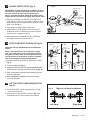
ADJUST SUPPLY STOP; Fig. 13
IMPORTANT: To avoid overowing, the SUPPLY STOP (3)
must never be opened to the point where the ow from
the valve exceeds the ow capacity of the xture.
Valve is designed to provide stated ush volume with a
25 gpm ow rate for toilet and 10 gpm ow rate for urinal.
1. Remove COVER (2) from SUPPLY STOP (3).Turn on
water supply 1/4 turn to 1/2 turn(CCW) and test for leaks.
Note: Unit may ush for approximately 5 to 10 sec. when
water is rst turned on.
2. Push down on HANDLE (4) to initiate ush.
3. Adjust SUPPLY STOP (3) after each ush until the
stated ush volume is achieved, no splashing occurs
and the xture is properly cleansed.
4. When adjustment is complete, reinstall COVER (2)
and tighten to ensure vandal-resistance.
12
HOW TO RETROFIT OUR VALVE; Fig. 14
(Replaces Industry Standard Manual and Electronic
Valves)
Note: In most Retrots the wall escutcheon, supply
stop, cover tube and vacuum breaker do not have to
be replaced. If these items do need replacement they
must be purchased separately or order the complete
ush valve assembly from American Standard.
1. Remove COVER (1) from SUPPLY STOP (2) if installed.
Fig. 14.
2. Tu r n water supply off. Fig. 14.
3. Unthread COUPLING NUT (3) and VACUUM BREAKER
COUPLING NUT (4). Remove FLUSH VALVE (5).Fig. 4a.
4. Clean all threaded connections before installing the new
ush valve. Fig. 14a.
5. Refer to Sections 4, 5 and 6 to complete the retrot
installation. Fig. 14b.
13
LEFT OR RIGHT HAND INSTALLATION;
Fig. 15
1. The FLUSH VALVE can be installed either as a right
or left hand installation.
2. Orientate the FLUSH VALVE as shown in Fig. 13 to
desired position for a left or right hand installation.
Fig. 13
2
REMOVE COVER
CLOCKWISE CLOSES
CONTROL STOP
COUNTER-CLOCKWISE
OPENS CONTROL STOP
3
2
Fig. 14 Fig. 14a Fig. 14b
1
5
3
4
CLEAN
CONNECTIONS
Fig. 15
Right or Left Hand Installation
Left Hand Right Hand
M965890 Rev. 1.2 (9/19)
7
-
 1
1
-
 2
2
-
 3
3
-
 4
4
-
 5
5
-
 6
6
-
 7
7


American Standard 6147SM122.002 Installation guide
- Type
- Installation guide
- This manual is also suitable for
Ask a question and I''ll find the answer in the document
Finding information in a document is now easier with AI
Related papers
-
American Standard SMGOPIS.002 Installation guide
-
-
American Standard 6590525.020 Installation guide
-
American Standard 6065.761.002 Installation guide
-
-
-
-
-
-
Other documents
-
Toto UT447E#01 Installation guide
-
Zurn ZEMS6003AV User manual
-
Zurn ZEMS6000-WS1.0005 User manual
-
Sloan Valve 3916916 Installation guide
-
-
Sloan 8111 Installation guide
-
-
Zurn ZER6000AV-HET-CCP User manual
-
Sloan 3250407 Installation guide
-