Page is loading ...

MODEL # DC-4LG
03-31-11
ASSEMBLY INSTRUCTIONS


Dear Discovery Centers™ Customer,
Thank you for choosing to purchase and install a Discovery Centers commercial playsystem by UltraPlay®. We appreciate the
confi dence you have placed in our company, and we will strive to earn your trust.
This is your Owner’s Manual & Assembly Instructions booklet. We have designed this manual specifi cally for the products that
you have purchased. Included in this manual you will fi nd the following:
• Maintenance schedule & record • Product installation instructions
• Safety guidelines • 2-D top view drawings
• Warranty information • Ground plan
Please save this booklet for future reference.
The fi rst several pages of this booklet contain important and valuable information regarding the general placement, installation
and safety practices common to commercial play equipment. Please read this information carefully and use your best judgment
as to how these guidelines apply to your specifi c situation.
If you have any questions concerning your new equipment, you can contact a Discovery Centers Customer Service Representa-
tive at 1-800-458-5872 or reach them electronically by sending an e-mail to: customerservice@uplaytoday.com.
To register your equipment and activate your warranty, please go to www.ultraplay.com/productregistration within 30 days
of delivery. This will allow UltraPlay to have a record of your purchase in case of warranty claims.
For more information on Discovery Centers and UltraPlay products, please do not hesitate to give us a call or visit
uplaytoday.com & ultraplay.com.
Thank you for your business; we look forward to working with you on all of your future playground equipment projects!
Sincerely,
Discovery Centers by UltraPlay
A PlayCore
®
Company

2
Maintaining your playground equipment and its surrounding area is essential to minimizing the risk of injury to users as well
as maximizing its useful lifespan. UltraPlay STRONGLY recommends that you follow these Safety Guidelines in conjunction with
conducting periodic maintenance inspections using the accompanying Playground Maintenance Checklist.
When installing your playground, always consider local conditions. Good common sense works hand-in-hand with the instructions.
LOCATING YOUR PLAY STRUCTURE:
Comply with the following when choosing the location for your new equipment: Equipment shall be positioned to eliminate
confl icting traffi c patterns. As a general rule, allow at least 6’ of free space around the entire structure, EXCEPT for slide exits,
which require a distance X equal to the highest point of the sliding surface with a minimum of 72 inches and maximum of 96
inches from the edge of the slide. See Figure 1 below (example: a Slide from a 6 foot deck requires 6 feet of clear space with
resilient surfacing in front of its exit). Discovery Centers slides are 4 feet or shorter; therefore, the slide exit use zone is 72
inches. Swings must have a minimum of twice the swing beam height of free space in front and behind them for safe circulation.
See fi gure 2 below (example: a swing with an 8 foot high toprail requires 16 feet of free space in front and another 16 feet behind
it, for a total of 32 feet). These minimum areas should be fi lled with the appropriate resilient surface material. Read further for
resilient surfacing recommendations.
GENERAL COMMERCIAL PLAYGROUND SAFETY GUIDELINES (page 1 of 5)

3
GENERAL COMMERCIAL PLAYGROUND SAFETY GUIDELINES (Page 2 of 5)
Never overlap the safety zones of adjacent equipment. All separate play equipment must have its own safety zone, and these
cannot overlap. If you have an existing structure with a slide exit oriented toward your new one, add a minimum safety zone to
that of the existing slide to determine how far away you need to be.
Never install playground equipment near, around, or in conjunction with swimming pools, ponds, lakes or any other bodies of
water.
CHOOSING RESILIENT SURFACE MATERIAL:
Playground equipment must be installed on a soft, resilient, energy-absorbing ground surface. NEVER INSTALL EQUIPMENT ON
CONCRETE, ASPHALT OR EVEN GRASS! A fall on a hard surface from even as low as a 3 foot high deck has been found to result
in serious injury to the user. For most play equipment, these surfaces should contain a minimum of 12 inches of wood fi ber or
other loose fi ll material intended for playground surfacing use. For more information on the proper surfacing materials, call the
CPSC hotline at 1-800-638-2772.
Soft, resilient surfacing should be placed in the use zones of all equipment, as specifi ed for each type of equipment, and at
depths to meet the critical fall heights as specifi ed by the U.S. Product Safety Commission, ASTM standard F1487 and Canadian
Standard CAN/CSA-Z-614. Equipment should be placed to eliminate confl icting traffi c patterns.
Tip: If your surfacing is of the loose variety, checking for proper depth over time can be made easy by applying a non-removable
fl uorescent tape of paint in a bright color at the proper level on each upright post. Thereafter, as the resilient material compacts
or washes away, the person responsible for regular maintenance inspections can easily see it must be replenished as the marks
become visible.
OVERHEAD OBSTRUCTIONS:
Overhead obstructions within the use zones of playground equipment that are not part of the play structure (for example, tree
limbs) shall be at least 84 inches (2130 mm) above each designated play surface or 84 inches (2130 mm) above the pivot point
of swings.
All overhead utility line clearances above the use zone areas shall comply with all local, state, and national codes, such as the
National Electrical Safety Code. For specifi c overhead obstruction requirements, refer to the CPSC and ASTM F1487 and use the
more stringent of the two.

4
CATCH POINT & PROTRUDING HARDWARE:
There should be no dangerous pieces of hardware, such as protruding bolt ends and narrow gaps in metal connections or open
“S” hooks at the top and bottom of swings. Exposed hardware can cut children, puncture skin, or catch clothing drawstrings,
which could strangle a child.
All protruding nuts and bolts should be eliminated; sharp edges on pipes should be capped or removed. Check for bent, broken,
or severely worn pipe and replace. Examine slide bedways, bedrails, handrails and exits for foreign objects, holes, and rough
edges.
TRIPPING HAZARDS:
There should be no exposed concrete footings, abrupt changes in surface elevations, tree roots, tree stumps, and rocks, which
can trip children and adults. Check for trip hazards, such as the balance beam support posts, or environmental trip hazards,
such as rocks or roots in the play area. Make all necessary improvements or repairs.
AFTER THE EQUIPMENT IS IN USE:
• Never add components not intended for use with this product.
• Never install other play equipment, fencing, landscaping, etc., which encroach upon the safety zones of this equipment.
• Check overall stability and rigidity of all play equipment.
• Check for proper assembly, installation and ground anchoring.
• Check and re-tighten all fasteners after the fi rst few days of use and again after three weeks of use. Thereafter, exercise
normal maintenance procedures. Use of a thread-locking compound on the threads of bolts can prevent persistent loosening.
• Swing “S” hooks must be completely closed. Replace worn “S” hooks and never re-use them.
GENERAL COMMERCIAL PLAYGROUND SAFETY GUIDELINES (Page 3 of 5)

5
GENERAL COMMERCIAL PLAYGROUND SAFETY GUIDELINES (Page 4 of 5)
ROUTINE MAINTENANCE:
Regularly inspect and maintain your playground equipment and its surrounding area to ensure the safety of the user. Proper
maintenance of Discovery Centers equipment includes using the accompanying Playground Maintenance Checklist found in
the back of this booklet to identify areas requiring repairs or replacement, and barricading the equipment to prevent use while
corrections are being made.
As the Owner/Operator of the equipment, you should establish and maintain detailed installation, inspection, maintenance,
and repair records for each public-use playground equipment area. Find out if your playground has a designated offi cial who
periodically inspects the play equipment for preventative maintenance. This includes: replacing missing, broken or worn-out
components; securing hardware; checking for deterioration in the metal or plastic materials; maintaining the proper 12 inch
depth of surfacing material; and cleaning up debris.
Following are some regular maintenance areas of note:
• Check for and repair damage caused by wear or vandalism, a major factor in injury causing situations.
• Proper maintenance of Discovery Centers equipment requires regular tightening of all bolts, nuts, set screws and other
hardware.
• All equipment should be free of rust and repainted with an appropriate lead-free paint whenever necessary to deter rusting.
This should also be done for any chipped or peeling areas.
• Regular checking of all parts, casting, etc., should be made. If part is broken or worn it should be replaced immediately.
• Check for loose spring castings and tighten.
• Check for missing or broken parts, rungs, or steps and repair as necessary.
• Replace worn or damaged strap seats or other swing seats.
• Check for worn chains and replace them as needed.
• Check to be sure there is free movement of swing hanger and other moving attached parts.
• Check the vertical distance between the underside of the occupied swing seat and the protective surface. It should measure
no less than 12 inches. Adjust swing seat height as necessary.
• Check for deformation of open “S” hooks, shackles, rings, links, etc. Check “S” hooks for excessive wear, making sure they are
properly closed; never reuse an “S” hook.
• Check for worn swing hangers and chain. When these areas are identifi ed, replacements should be made.
- Continued next page

6
• Check for missing, damaged, or loose swing seats. Check rubber seats for wear, sharp edges/points, scorching, or burn
damage. Repair and replace as needed.
• Check for swing chain wrapped around top rail and if found, unwrap. Replace chains as necessary.
• Check for hard surfaces and correct, including under swings, slides, etc., where loose surfacing may have been kicked away.
Refer to CPSC surfacing requirements.
• Check for surfacing material that is worn or scattered and restore.
• Debris, broken glass, trash, or other foreign objects within or on the play area/equipment should be removed.
• Check for poor drainage areas and repair.
• Check concrete footings to see if they are exposed, cracked, or loose in the ground and repair as necessary.
• Check for lack of lubrication on all moving parts and lubricate as needed.
• Check crush points (exposed mechanisms, junctures of moving components) and eliminate.
• Check for broken support/anchors. Stability in ground, structures should not be easily swayed; connections should be solid
and adequately secured.
• Check all posts in ground for corrosion or rot below grade.
• Check exit areas of slides. The exit area should be no more than 11 inches from the protective surface for slides under 4 feet
high. For slides over 4 feet high, the height of the exit region from the surface should be between 7 and 15 inches.
• Check the surface area around slide exit for erosion and other damage and repair if necessary.
• Check for visible cracks, bending, warping, rusting, or breakage of any component and repair as needed.
• Check for accessible sharp edges or points. Check for protruding bars, bolts, nuts, etc. Eliminate these conditions.
• Check for exposed ends of tubing that should be covered with plugs or caps.
• Check for loose bolts, nuts, etc. and tighten.
• Check for broken or missing rails, steps, rungs, or seats and replace.
• Replace broken springs and seats on spring riders and other similar play events.
GENERAL COMMERCIAL PLAYGROUND SAFETY GUIDELINES (Page 5 of 5)

LIMITED WARRANTIES
• Upright Posts
• Post Caps
• Hardware
• Moving Parts
• Freestanding and
other components
• Rotomolded Plastic
Components
• Blowmolded Plastic
Components
• Ground Mount Metal Parts
Materials and Workmanship
Ten Years
Five Years
One Year
Materials and Workmanship
All warranties specifically exclude damage caused by man-made or natural disasters, vandalism, negligence,
improper installation or improper use, modification, changes in appearance resulting from weathering,
scratches, dents, discoloration, normal wear and tear, or marring as a result of public or private use.
Claims are limited to replacement of equipment only and do not include any costs associated with labor,
removal or installation of the original or replacement product.
Warranties are valid only if products are installed and maintained in accordance with UltraPlay installation
instructions and use of approved parts.
Materials and Workmanship
To register your equipment and activate your warranty, please go to www.ultraplay.com/productregistration
within 30 days of delivery. This will allow UltraPlay to have a record of your purchase in case of warranty claims.

8
WARRANTY DETAILS
UltraPlay warrants its products to be free from defects in materials and/or workmanship, subject to normal usage and installation, for
a period of 1-year from the date of shipment to the original purchaser. In the event of a claim under this warranty, UltraPlay will replace
the component at no cost within the first 12 months from date of shipment to the original customer. Equipment not specifically
addressed in the following paragraphs is also subject to this limited 1 year warranty against defects in materials and/or workmanship.
TEN-YEAR LIMITED WARRANTY ON UPRIGHT POSTS, CAPS, AND HARDWARE
UltraPlay provides a limited warranty on Discovery Centers metal upright posts, caps, and hardware to be free from defects in materials
or workmanship against structural failure which causes the product to become unfit for its intended use, subject to normal usage and
installation, for a period of 10 years from the date of shipment to the original customer.
FIVE-YEAR LIMITED WARRANTY ON ROTOMOLDED AND BLOWMOLDED PLASTIC COMPONENTS
UltraPlay provides a limited warranty on rotomolded and blowmolded plastic components such as the following plastic parts: slides,
climbers, roofs, panels. These components are warranted to be free from defects in materials or workmanship, subject to normal
usage and installation, for a period of 5 years from the date of shipment to the original customer.
FIVE-YEAR LIMITED WARRANTY ON GROUND-MOUNT METAL PARTS
UltraPlay Systems provides a limited warranty on metal footers, inground footers, surface mount plates, ground spikes, slide and
climber mounting posts and plates to be free from defects in materials or workmanship against structural failure which causes the
product to become unfit for its intended use, subject to normal usage and installation, for a period of 5 years from the date of
shipment to the original customer.
ONE-YEAR LIMITED WARRANTY ON COMPONENTS WITH MOVING PARTS
UltraPlay Systems provides a limited warranty on components with moving parts, freestanding components such as spring riders and
swings, and all other components not specifically named above to be free from defects in materials or workmanship against structural
failure which causes the product to become unfit for its intended use, subject to normal usage and installation, for a period of 1 year
from the date of shipment to the original customer.
LIMITED WARRANTY ON SITE FURNISHINGS
UltraPlay provides a five-year limited warranty on the finish of thermoplastic coated site furnishings from the date of shipment to the
original customer. Additionally, all site furnishings are guaranteed to be free from defects in materials or workmanship for one-year
from the date of shipment to the original customer.
All warranties specifically exclude damage caused by man-made or natural disasters, vandalism, negligence, improper installation or
improper use, modification, changes in appearance resulting from weathering, scratches, dents, discoloration, normal wear and tear,
or marring as a result of public or private use. Claims are limited to replacement of equipment only and do not include any costs
associated with labor, removal or installation of the original or replacement product. Warranties are valid only if products are installed
and maintained in accordance with UltraPlay installation instructions and use of approved parts. This warranty is applicable to the
original owner only. Warranties are non-transferable.

9
Claim Procedure: To make a warranty claim, send your written statement of claim, photographs of defective equipment,
and the original purchase invoice or invoice number to:
Discovery Centers
Customer Service
1675 Locust Street
Red Bud, IL 62278
Or Contact a Customer Service Representative at:
1-800-458-5872
Within 60 days of notice of claim under warranty, UltraPlay will make arrangements to replace the damaged product.
UltraPlay will cover freight costs within the continental United States. UltraPlay is not
responsible for freight costs
associated with products located outside the continental United States. UltraPlay Systems reserves the right to inspect all
products identified as defective. Photos of defective equipment may be required to accompany warranty claims. Since
warranty limitations and exclusions may vary from state to state, you should check any specific warranty rights in your
state.
Da
te of Purchase:_______________________
Purchaser:_____________________________
UltraPlay Invoice Number:________________
____________________________________
Authorized UltraPlay Signature
____________________________________
Title
Visit UltraPlay on the web at www.ultraplay.com & www.uplaytoday.com
CLAIM PROCEDURE

10
Consider these UltraPlay freestanding play components
to enhance the fun of your play environment!
4’ Freestanding Slide
(Slide-P)
Spring See Saw
(02-07-0055)
Horse Spring Rider
(02-07-0053)
Truck Spring Rider
(02-07-0054)
Early Childhood
Horizontal Ladder
(PJHLAD)
Freestanding Crawl Tunnel
(02-07-0057)
Balance Beam
(ZBAL-8)
Single Bay Swing 2-5
(PBP-8-1C)
UPstart (Single Deck)
[A-BASE-P(N)]
Ultraplay offers a variety of playground solutions to meet your specifi c needs. Check out UplayToday
TM
by UltraPlay in addition
to other Discovery Centers playgrounds for your future projects. at www.ultraplay.com or www.uplaytoday.com.

11
IMPORTANT! Please read the entire Installation Instructions packet before beginning the installation.
UltraPlay has designed Discovery Centers to take advantage of all Consumer Product Safety Commission (CPSC) and ASTM
guidelines in force at the time of purchase in an effort to prevent playground accidents. However, because studies have shown
most playground injuries result from accidental falls, you, as the new owner of this equipment are responsible for providing an
adequately resilient play surface under and around all playground equipment. Please refer to the accompanying Safety
Guidelines as well as CPSC guidelines and this document for examples of such surfacing.
We would like to provide the following suggested guidelines for your play environment:
• Refer to the Use Zone and note the Minimum Area Required shown for this structure. This area must be fi lled with adequate
resilient play surface material, and must be clear of all obstacles, including but not limited to trees, curbing, sidewalk, fence,
other play equipment, rocks and landscaping, etc.
• Acceptable play surfaces include sand, mulch, fi ne gravel or shredded belt-less tires, if installed at the appropriate depths per
CPSC guidelines for play surfacing.
• When using loose fi ll surfacing, a minimum of 6” depth is recommended by the CPSC. UltraPlay
recommends an additional 6”, for a total of 12”, to combat the fast compacting characteristics of these materials. Surfaces
must be checked at least weekly for compacting, which reduces resiliency signifi cantly.
• Unitary resilient surfacing designed for playground use, including rubber tiles, poured-in-place rubber surfacing, bonded rubber
surfacing and synthetic playground turf is also recommended.
• Surfaces such as asphalt, concrete, gravel, or sod are not acceptable for use under playground equipment, or anywhere within
the stated Minimum Area Required.
• Close supervision of children playing on or around the structure is strongly recommended, along with classroom and/or home
instructions on safer behavior on the playground equipment. The full supervision of playgrounds is the responsibility of the owner
once the play structure has been properly installed.
GENERAL INSTALLATION GUIDELINES (Page 1 of 4)

12
GENERAL INSTALLATION GUIDELINES (Page 2 of 4)
TOOLS REQUIRED:
UltraPlay supplies only the special wrenches and bits required to fasten the “tamper-resistant” hardware and components. Refer
to the Tools Required page for a detailed list. A power post hole digger may facilitate installation in some circumstances.
1. Compare all parts received to the packing list. Notify UltraPlay immediately of any missing parts. We are not responsible for
parts discovered missing over 10 days after receipt of the shipment.
2. Refer to the Use Zone to ensure this structure will fi t into your actual site area. Note the Minimum Area Required
measurements to determine clear space required. A minimum of 6’ clearance is required between any obstacles and your
structure. EXCEPT for slide exits, which require a distance X equal to the highest point of sliding surface with a minimum of 6’
and a maximum of 8’ from the edge of the slide (example: A Slide from a 6’ high deck requires 6’ of clear space with resilient
surfacing in front of its exit).
3. Site selection should include considerations of what is a safer and appropriate play area:
• A level and clear site is ideal, free of power lines or electrical equipment.
• Do not install play equipment near any bodies of water.
• If adjacent to a street with traffi c, ensure adequate fencing acts as a barrier to children running into danger.
4. Site layout should include accurate measurement and marking of all footings prior to any installation. Use the dimensions
shown between footings on the Use Zone to plot out the actual footprint of the play structure before doing any digging. Also
locate any free-standing play equipment in the same way, providing the necessary clearance between the equipment as well as
any fences, trees, etc. Ensure at this time you have enough total space for the equipment to be installed.
5. If using Inground footers, excavate holes as shown in the Use Zone using a string line. An optional string line level is very
helpful. If a level and clear site is not possible, adjust the depth of the footings to maintain a minimum depth of 18” for support
posts at the lowest grade. NOTE: If soil conditions are very loose or otherwise unstable, a larger diameter footing may be
required. Inquire with local contractors for appropriate recommendations.
6. Begin your Discovery Centers installation by erecting the decks as shown within the following instructions. Once all decks are
installed, components such as slides, climbers, etc., can be connected per their respective assembly instructions.
7. CPSC guidelines mandate that there shall be no gaps present in the playground equipment that are between 3-1/2” and 9”.

UltraPlay Play Systems
800.458.5872 • www.ultraplay.com
13
GENERAL INSTALLATION GUIDELINES (Page 3 of 4)
The positioning of certain components by the installer can affect these criteria, so you should always measure distances
created when attaching components in order to avoid these spaces which can cause entrapment of a child using the equipment.
Also, ASTM requires that no more than 2 threads of a bolt can protrude from the nut. Any excess threads should be fi led down and
made smooth to the touch.
8. When concrete is poured, be sure to keep the top 4” below the grade, and sloped away from the post to promote good water
drainage. Wash off any concrete, that may have splashed onto the post before it dries. Allow all concrete to harden a
minimum of 48 hours before allowing use.
SAFETY DURING INSTALLATION:
1. Before doing any excavation, inquire about any existing underground utilities.
2. Do not leave the job site unattended without making sure that all fastening hardware on all equipment are tightened. It is
also strongly recommended that all installation areas be roped off with clearly marked warning signs posted. Any open footings
should be covered with plywood or other suitable material. Even during installation, it has been found that children may attempt
to use the unattended equipment, thereby risking accidents.
3. If concrete footings and inground footers are being used, it is strongly recommended that the installation area should
remain roped off for at least 48 hours after the last concrete footing is poured. Children should not be allowed to use the
equipment during this period so that concrete has a chance to fully cure.
4. Do not attach swing chains or similar moving components until after all construction is complete and resilient surfacing
material has been installed. Remember that any equipment, which appears to be complete and functional, will invite
unauthorized use regardless of its actual state of readiness.
Finally, if you should have any questions regarding the proper installation of this equipment, please contact UltraPlay at:
UltraPlay
Discovery Centers Customer Service
1675 Locust Street, Red Bud, IL 62278
Phone:1-800-458-5872 • Fax: 1-618-282-8202
E-mail: customerservice@uplaytoday.com

14
The Discovery Center is a modular play system that uses a grid system for the playground layout.
It is very important to spend a few minutes before beginning the installation to ensure that
components are inventoried and organized properly. INVENTORY MUST BE TAKEN PER CARTON!
LOOK FOR THE NUMBERS!
Each metal post will have a NUMBER sticker on it that corresponds with the numbers on
the printed grid. Some grid numbers have an UPPER level post as well as a LOWER level post. All of
the LOWER level posts have ground mounting plates welded to them. The UPPER level posts do not.
The UPPER and LOWER posts will have matching numbers.
The UPPER level posts screw into the LOWER level posts using the “T” tool provided (see tools page).
The plastic components all have numbers on them that correspond with the grid and post numbers.
This will enable you to verify that the correct component is installed in the correct location. When
installing the plasitic post covers, simply match up the numbers on the plastic with the numbers on
the vertical posts.
GENERAL INSTALLATION GUIDELINES (Page 4 of 4)

UltraPlay Play Systems
800.458.5872 • www.ultraplay.com
15
TOOLS REQUIRED
MEASURING TAPE
UTILITY KNIFE
RUBBER MALLET
4LB HAMMER
LEVEL
POST TIGHTING
“T” TOOL
(included)
TORX HEAD
WRENCHES/BITS
(included)
DRILL
3/8”
MASONRY DRILL BIT
LOCTITE
6mm
4mm
ALAN HEAD BITS
(included)
WRENCH
(included)
13mm
17mm

UltraPlay Play Systems
800.458.5872 • www.ultraplay.com
16
HARDWARE REFERENCE
18” Ground Spike (02-07-0048) (not to scale)
M5 x 3
”
(76mm) Self
-
tapping Screw (33
-
11
-
0600)
M8 Barrel Nut
(33-11-0501)
M8 Flat Washer
(33-11-0300)
M8 Lock Washer
(33-11-0301)
M8 Lock Nut
(33-11-0500)
M10 Lock Washer
(33-11-0201)
Extra Hardware
M10 Flat Washer
(33-11-0200)
M10 Barrel Nut
(33-11-0401)
M10 Lock Nut
(33-11-0400)
M10 B.H.C.S. Bolts NOTE: Your play structure may not use all hardware listed
M8 B.H.C.S. Bolts
1/2”
3/4”
1” 1-3/16” 1-3/8” 1-9/16” 2” 2-3/8” 2-3/4” 3-1/8”
13mm
20mm 25mm 30mm 35mm 40mm 50mm 60mm 70mm 80mm
3/4”
1”1-3/16”1-3/8”1-9/16”1-3/4”
2-3/4”4”
20mm25mm30mm35mm40mm45mm
70mm100mm
33-11-0108 33-11-0107
33-11-0109 33-11-0106 33-11-0105
33-11-0104 33-11-0103 33-11-0102
1/2”
13mm
33-11-0101
33-11-0001 33-11-0002 33-11-0003 33-11-0004 33-11-0005 33-11-0006 33-11-0010 33-11-0007 33-11-0008 33-11-0011

UltraPlay Play Systems
800.458.5872 • www.ultraplay.com
17
USE ZONE
6'
6'
6'
6'
6'
6'
MINIMUM USE ZONE* REQUIRED
NOTE:
Equipment shall be positioned to eliminate
conflicting traffic patterns. As a general
rule, allow at least 6’ of freespace
around the entire structure.
IMPORTANT: Never install play equipment over hard, unresilient
surfaces such as asphalt, concrete or compacted earth. It is the
owner’s responsibility to ensure the “minimum area required”
contains an appropriate amount of resilient material to cushion
accidental falls.
TOP VIEW
* The USE ZONE is the area beneath
and immediately adjacent to a play
structure or equipment that is designed
for unrestricted circulation around the
equipment and on whose surface it is
predicted that a user would land when
falling from or exiting the equipment.
USE ZONE
Vine Climber
Short Straight Slide
Platform
Bench
Straight
Slide
28'
27'

UltraPlay Play Systems
800.458.5872 • www.ultraplay.com
18
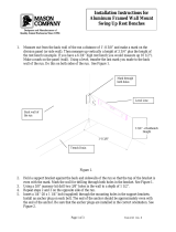
POST PLACEMENT/HOLE LOCATIONS
45-1/4” (1150mm)
USE ZONE
Placement for
12” Diameter x 18” Deep Holes
for In-ground installation
IMPORTANT: Never install play equipment
over hard, unresilient surfaces such as
asphalt, concrete or compacted earth. It is
the owner’s responsibility to ensure the
“minimum area required” contains an
appropriate amount of resilient material to
cushion accidental falls.
1. Review Use Zone. Begin placement of Deck Post 1.
NOTE: Survey flags may be used to mark
the placement of each hole.
2. Measure from first Deck Post to mark the
positon of the remaining posts/holes. Check for
squareness using the 45-1/4” diagonal dimension.
NOTE: All remaining dimensions are based
off of the Deck Post placement.
3. Measure from the center of a Deck Post using
the dimensions provided for each remaining hole.
Concrete Required(if applicable) :
Approx. .7 Cubic Yards (.5 Cubic Meters)
NOTE: Suggested Min. concrete
rating: 3000PSI
32.25”
69”
55.5”
16”
53”
76”
32.25”
12”
18”
1
1
2
3
5
7
4
6
89
10
Vine Climber
Short Straight Slide
Platform
All Posts are numbered
11’
8’
28'
27'
65”(1651mm)
67”(1702mm)
Straight
Slide
TOP VIEW
NOTE:
All dimensions are
measured from the
center of the posts/holes
/