Hoshizaki F-500BAF User manual
- Category
- Ice cube makers
- Type
- User manual
This manual is also suitable for

INSTRUCTION MANUAL
ISSUED:
April 13, 1998
F-500BAF(-C)
SELF-CONTAINED FLAKER
Reliability is a
beautiful thing
TM
REVISED:
December 30, 2004

2
HOSHIZAKI AMERICA, INC.
618 Highway 74 South
Peachtree City, GA 30269
Attn: HOSHIZAKI Technical Support Department
Phone: 1-800-233-1940 Technical Service
(770) 487-2331
Fax: (770) 487-3360
Web Site: www.hoshizakiamerica.com
Note: To expedite assistance, all correspondence/communication MUST include the
following information:
• Model Number
• Serial Number
• Complete and detailed explanation of the problem
Only qualified service technicians should attempt to install, service or maintain
this icemaker. No installation, service or maintenance should be undertaken
until the technician has thoroughly read this Instruction Manual. Likewise, the
owner/manager should not proceed to operate the icemaker until the installer
has instructed them on its proper operation.
HOSHIZAKI provides this manual primarily to assist qualified service technicians in the
installation, maintenance and service of the icemaker.
Should the reader have any questions or concerns which have not been satisfactorily
addressed, please call or write to the HOSHIZAKI Technical Support Department for
assistance.
IMPORTANT

3
• Please review this manual. It should be read carefully before the icemaker is installed
and operated. Only qualified service technicians should install, service and maintain the
icemaker. This manual should be made available to the technician prior to installation,
maintenance or service.
• Keep this manual with the icemaker for later reference.
CONTENTS
I. Specifications .................................................................................................................... 4
1. Nameplate Rating ........................................................................................................ 4
2. Dimensions/Connections ............................................................................................. 5
II. Installation and Operating Instructions .............................................................................. 6
1. Checks Before Installation ............................................................................................ 6
2. How to Remove Panels ................................................................................................ 6
3. Location ........................................................................................................................ 7
4. Setup ............................................................................................................................ 7
5. Electrical Connection ................................................................................................... 8
6. Water Supply and Drain Connections ........................................................................... 9
7. Final Check List.......................................................................................................... 10
8. Startup ........................................................................................................................ 11
9. Preparing the Icemaker for Long Storage ................................................................... 12
III. Cleaning and Maintenance ............................................................................................ 13
1. Cleaning and Sanitizing Instructions .......................................................................... 13
[a] Cleaning Solution ................................................................................................ 13
[b] Cleaning Procedure ............................................................................................ 13
[c] Sanitizing Solution............................................................................................... 14
[d] Sanitizing Procedure - Initial................................................................................ 15
[e] Sanitizing Procedure - Final ................................................................................ 15
2. Maintenance ............................................................................................................... 17

4
MODEL NUMBER
SERIAL NUMBER
AC SUPPLY VOLTAGE
COMPRESSOR
GEAR MOTOR
FAN MOTOR
OTHER
MAXIMUM FUSE USE
MAX. HACR BREAKER (USA ONLY)
MAX. CIRC. BREAKER (CANADA ONLY)
MINIMUM CIRCUIT AMPACITY
DESIGN PRESSURE
REFRIGERANT 404A
MOTOR-COMPRESSOR THERMALLY PROTECTED
NOT INTENDED FOR OUTDOOR USE
120V 0.81FLA 30W
120V 1.8FLA 80W
120V 0.08A
20 AMPS
20 AMPS
20 AMPS
20 AMPS
HI-460PSI LO-290PSI
1 lb.
HOSHIZAKI ICE MAKER
F-500BAF
120V
7.9RLA 51LRA
I. Specifications
1. Nameplate Rating
[a] F-500BAF, F-500BAF-C (Air-cooled)
See the nameplate for electrical and
refrigeration specifications. This nameplate is
located on the upper right hand side of the rear
panel.
We reserve the right to make changes in specifications and design without prior notice.
NOTE: Only the “MODEL NUMBER” is replaced for F-500BAF-C.
HOSHIZAKI AMERICA, INC.
Peachtree City, GA
115-120/60/1 (3 WIRE WITH NEUTRAL FOR 115V)

5
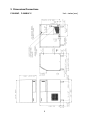
2. Dimensions/Connections
F-500BAF, F-500BAF-C
Unit = inches [mm.]

6
II. Installation and Operating Instructions
1. Checks Before Installation
WARNING
Remove shipping carton, tape(s) and packing. If packing material is left in the
icemaker, it will not work properly.
IMPORTANT
Ensure all components, fasteners and thumbscrews are securely in place.
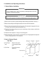
1) Remove the front panel to prevent damage when installing the icemaker. See Fig. 1.
2) Remove the package containing the accessories from inside the icemaker.
3) Remove the protective plastic film from the panels. If the icemaker is exposed to the sun
or to heat, remove the film after the icemaker cools.
4) Check that the refrigerant lines do not rub or touch lines or other surfaces, and that the
fan blade turns freely.
5) Check that the compressor is snug on all mounting pads.
6) See the nameplate on the rear panel, and check that your voltage supplied corresponds
with the voltage specified on the nameplate.
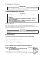
2. How to Remove Panels
- See Fig. 1
a) Front Panel . . . . . Remove the screws.
(left)
Lift up and pull toward
you.
b) Top Panel . . . . . . Remove the screws,
then lift off.
Fig. 1

7
3. Location
WARNING
This icemaker is not intended for outdoor use. Normal operating ambient
temperature should be within +45°F to +100°F; Normal operating water
temperature should be within +45°F to +90°F. Operation of the icemaker, for
extended periods, outside of these normal temperature ranges may affect
production capacity.
For best operating results:
• Icemaker should not be located next to ovens, grills or other high heat producing
equipment.
• Location should provide a firm and level foundation for the equipment.
• Allow 6" clearance at rear and sides for proper air circulation and ease of maintenance
and /or service should they be required. Allow 24" clearance at top to allow for
removal of the auger.
4. Setup
1) Unpack the icemaker and remove all shipping carton, tape(s) and packing.
2) Provide four 6" adjustable legs and attach them to the bottom of the icemaker.
3) Position the icemaker in the selected permanent site.
4) Level the icemaker in both the left-to-right and front-to-rear directions.

8
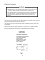
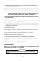
5. Electrical Connection
WARNING
1. Electrical connection must be made in accordance with the instructions on a
“WARNING” tag provided with the pig tail leads in the junction box.
2. This icemaker requires a ground that meets the national and local electrical
code requirements. To prevent possible electrical shock to individuals or
extensive damage to the equipment, install a proper ground wire to the
icemaker.
• The white lead must be connected to the neutral conductor of the power source. Miswiring
results in severe damage to the icemaker. See Fig. 2.
• This icemaker must have a separate power supply or receptacle of proper capacity. See
the nameplate.
• The opening for the power supply connection is 7/8" DIA to fit a 1/2" trade size conduit.
• Usually an electrical permit and services of a licensed electrician are required.
Fig. 2

9
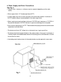
6. Water Supply and Drain Connections
See Fig. 3
• External filters, strainers or softeners may be required depending on the water
quality.
• Water supply inlet is 1/2" female pipe thread (FPT).
• A water supply line shut-off valve and drain valve should be installed. A minimum of
3/8" OD copper tubing is recommended for the water supply lines.
• Water supply pressure should be a minimum of 10 PSIG and a maximum of 113 PSIG. If
the pressure exceeds 113 PSIG, the use of a pressure reducing valve is required.
• Drain outlet for icemaking is 3/4" FPT. The icemaker drain piping connection must be made
separately from the bin drain.
• The drains must have 1/4" fall per foot on horizontal runs to get a good flow.
• The drains should not be piped directly to the sewer system. An air gap of a minimum of
2 vertical inches should be between the end of the drain pipe from the icemaker or the ice
bin and the floor drain.
• A plumbing permit and services of a licensed plumber may be required in some areas.
Fig. 3

10
7. Final Check List
1) Is the icemaker level?
2) Is the icemaker in a site where the ambient temperature is within +45°F to +100°F and
the water temperature within +45°F to +90°F all year around?
3) Is there at least 6" clearance at rear and sides and 24" at top for maintenance or
service?
4) Have all shipping carton, tape(s) and packing been removed from the icemaker?
5) Are all components, fasteners and thumbscrews securely in place?
6) Have all electrical and piping connections been made?
7) Has the power supply voltage been checked or tested against the nameplate rating and
the correct voltage selected? And has a proper ground been installed in the icemaker?
8) Are the water supply line shut-off valve and drain valve installed? Has the water
supply pressure been checked to ensure a minimum of 10 PSIG and a maximum of
113 PSIG?
Note: The icemaker may stop running when the water supply is OFF, or if the pressure
is below 10 PSIG. When the proper water pressure is reached, the icemaker
automatically starts running again.
9) Have the compressor hold-down bolts and refrigerant lines been checked against
vibration and possible failure?
10) Has the bin control switch been checked for correct operation? Move the actuator
located on the inside of the bin top panel. The compressor should stop within
90 seconds, and the gear motor within 150 seconds.
11) Has the end user been given the instruction manual, and instructed on how to operate
the icemaker and the importance of the recommended periodic maintenance?
12) Has the end user been given the name and telephone number of an authorized service
agent?
13) Has the warranty tag been filled out and forwarded to the factory for warranty
registration?
14) Have the safety switch brackets moved out of location during shipping? Check on top of
the spout and connecting the evaporator to the bin wall.

11
15) Has the safety switch been checked for correct operation? Activate the safety switch on
top of the spout. The ice machine should shut down immediately. Turn the ice machine
off, then back on, to reset.
8. Startup
WARNING
1. All parts are factory-adjusted. Improper adjustments may result in failure.
2. If the unit is turned off, wait for at least 3 minutes before restarting the icemaker
to prevent damage to the compressor.
1) Clean the storage bin. (See “III. 2. Maintenance.”)
2) Open the water supply line shut-off valve.
3) Remove the front panel.
4) Move the flush switch on the control box to the “ICE” position.
5) Turn on the power switch on the control box.
6) Replace the front panel in its correct position.
7) Turn on the power supply.

12
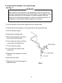
9. Preparing the Icemaker for Long Storage
- See Fig. 4
WARNING
When shutting off the icemaker for an extended time, drain out all water from
the water line and remove the ice from the storage bin. The storage bin should
be cleaned and dried. Drain the icemaker to prevent damage to the water
supply line at sub-freezing temperatures, using air or carbon dioxide. Shut off
the icemaker until the proper ambient temperature is resumed.
1) Run the icemaker with the water supply line shut-off valve closed.
2) Open the drain valve and blow out the water inlet line by using air pressure.
3) Turn off the power supply.
4) Remove the front panel (left).
5) Move the flush switch on the control
box to the “FLUSH” position.
6) Turn on the power supply, and drain
out all water from the water line.
7) Turn off the power supply.
8) Turn off the power switch on the
control box.
9) Replace the front panel in its correct
position.
10)
Close the drain valve.
11)
Remove all ice from the storage bin,
and clean the bin.
Fig. 4

13
III. Cleaning and Maintenance
IMPORTANT
Ensure all components, fasteners and thumbscrews are securely in place after
any maintenance or cleaning is done to the equipment.
1. Cleaning and Sanitizing Instructions
WARNING
1. HOSHIZAKI recommends cleaning this unit at least once a year. More
frequent cleaning, however, may be required in some existing water
conditions.
2. To prevent injury to individuals and damage to the icemaker, do not use
ammonia type cleaners.
3. Always wear liquid-proof gloves to prevent the cleaning and sanitizing
solutions from coming into contact with skin.
[a] Cleaning Solution
Dilute 4.8 fl. oz. (142 ml) of recommended cleaner Hoshizaki “Scale Away” or
“LIME-A-WAY” (Economics Laboratory, Inc.) with 0.8 gallons (3 l) of warm water. This is a
minimum amount. Make more solution if necessary.
IMPORTANT
For safety and maximum effectiveness, use the solution immediately after
dilution.
[b] Cleaning Procedure
1) Remove the front panel and the top panel, then turn off the power supply.
2) Close the water supply line shut-off valve.
3) Remove all ice from the storage bin.
4) Move the flush switch to the “FLUSH” position.
5) Turn on the power supply and drain out all water from the water line.
6) Turn off the power supply.
Note: This unit is designed to start operating when the
reservoir is filled with water.
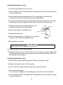
7) In the storage bin, remove the thumbscrews attaching
spout (B), then remove spout (B) and spout packing (B).
Thumbscrews
Spout (B)
Spout Packing (B)
Fig. 5

14
8) Remove the thumbscrews attaching spout (A) to the evaporator assembly and lift off
spout (A) and spout packing (A).
9) Pour the cleaning solution over the extruding head until the evaporator assembly and
the reservoir are filled and the solution starts to overflow into the drain pan.
Note: If there is excess scale on the extruding head, fill the evaporator assembly and
reservoir as described above, then use a clamp on the reservoir hose between the
reservoir and evaporator assembly to block flow. Pour additional cleaning fluid
over the extruding head until the evaporator assembly is completely full.
10) Using the thumbscrews, replace spouts (A) and (B) and spout packings (A) and (B) in
their correct positions.
11) Allow the icemaker to sit for about 10 minutes before operation. If you placed a clamp on
the reservoir hose in step 9, remove it before operation.
12) Move the flush switch to the “ICE” position, then turn on the power supply. Replace the
top panel and the front panel in their correct positions. Make ice using the solution until
the icemaker stops making ice.
13) Remove the front panel.
14) Move the flush switch to the “FLUSH” position to drain the remainder of the solution.
15) After the solution is drained, move the flush switch to the “ICE” position.
16) Replace the front panel in its correct position.
17) Open the water supply line shut-off valve, and supply water to the reservoir.
18) When the gear motor starts, remove the top panel and front panel. Turn off the power
supply.
19) Drain out all water from the water line. See 4) through 6).
[c] Sanitizing Solution
Dilute 2.5 fl. oz. (74 ml or 5 tbs) of IMS-II Sanitizer or a 5.25% sodium hypochlorite solution
(chlorine bleach) with 5 gallons (19 l) of warm water.
IMPORTANT
For safety and maximum effectiveness, use the solution immediately after
dilution.

15
[d] Sanitizing Procedure - Initial
1) Close the water supply line shut-off valve.
2) In the storage bin, remove the thumbscrews attaching spout (B), then remove spout (B)
and spout packing (B).
3) Remove the thumbscrews attaching spout (A) to the evaporator assembly and
lift off spout (A) and spout packing (A), and the cylinder packing.
4) Pour the sanitizinging solution over the extruding head until the evaporator assembly
and the reservoir are filled and the solution starts to overflow into the drain pan.
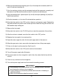
5) Remove the thumbscrews attaching the bin control
assembly to the inside of the bin top panel.
6) Remove the snap pin, shaft and actuator.
7) Remove the sliding door.
8) Soak the removed parts in .25 gallons (1 l) of sanitizing
solution for 10 minutes then wipe them down.
9) Rinse the parts thoroughly.
IMPORTANT
If the solution is left on these parts, they will rust.
10) Replace all parts in their correct positions.
11) Move the flush switch to the “ICE” position, then turn on the power supply. Replace the
top panel and the front panel in their correct positions. Make ice using the solution until
the icemaker stops making ice.
[e] Sanitizing Procedure - Final
1) Remove the front panel and the top panel, then turn off the power supply.
2) Move the flush switch to the “FLUSH” position.
3) Turn on the power supply and drain out all water from the water line.
4) Turn off the power supply.
Note: This unit is designed to start operating when the reservoir is filled with water.
5) In the storage bin, remove the thumbscrews attaching spout (B), then remove spout (B)
and spout packing (B).
Bracket
Thumbscrews
Shaft
Snap Pin
Actuator
Fig. 6

16
6) Remove the thumbscrews attaching spout (A) to the evaporator assembly and lift off
spout (A) and spout packing (A).
7) Pour the sanitizing solution over the extruding head until the evaporator assembly and
the reservoir are filled and the solution starts to overflow into the drain pan.
8) Using the thumbscrews, replace spouts (A) and (B) and spout packings (A) and (B) in
their correct positions.
9) Allow the icemaker to sit for about 10 minutes before operation.
10) Move the flush switch to the “ICE” position, then turn on the power supply. Replace the
top panel and the front panel in their correct positions. Make ice using the solution until
the icemaker stops making ice.
11) Remove the front panel.
12) Move the flush switch to the “FLUSH” position to drain the remainder of the solution.
13) After the solution is drained, move the flush switch to the “ICE” position.
14) Replace the front panel in its correct position.
15) Open the water supply line shut-off valve and supply water to the reservoir.
16) When the gear motor starts, remove the front panel and turn off the power supply.
17) Drain out all water from the water line. See 2) and 3).
18) Move the flush switch to the “ICE” position and run the icemaker.
19) Turn off the power supply after 30 minutes.
20) Pour warm water into the storage bin to melt all ice, then clean the bin liner with the
solution.
21) Flush out any solution from the storage bin.
22) Turn on the power supply and start the automatic icemaking process.
IMPORTANT
1. After cleaning, do not use ice made from the sanitizing solution. Be careful
not to leave any solution in the storage bin.
2. Follow carefully any instructions provided with the bottles of cleaning or
sanitizing solution.
3. Never run the icemaker when the reservoir is empty.

17
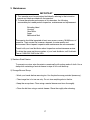
2. Maintenance
IMPORTANT
1. This icemaker must be maintained individually, referring to the instruction
manual and labels provided with the icemaker.
2. To have the optimum performance of this icemaker, the following
consumable parts need periodic inspection, maintenance and replacement:
Extruding Head
Housing
Gear Motor
Auger
Mechanical Seal
These parts should be inspected at least once a year or every 10,000 hours of
operation. Their service life, however, depends on water quality and
environment. More frequent inspection and maintenance are recommended.
Consult with your local distributor about inspection and maintenance service.
To obtain the name and phone number of your local distributor, call Hoshizaki
Care at 1-800-233-1940 in the USA.
1) Stainless Steel Exterior
To prevent corrosion, wipe the exterior occasionally with a clean and soft cloth. Use a
damp cloth containing a neutral cleaner to wipe off oil or dirt build up.
2) Storage Bin and Scoop
• Wash your hands before removing ice. Use the plastic scoop provided (accessory).
• The storage bin is for ice use only. Do not store anything else in the bin.
• Keep the scoop clean. Clean using a neutral cleaner and rinse thoroughly.
• Clean the bin liner using a neutral cleaner. Rinse thoroughly after cleaning.

3) Air Filter
A plastic mesh air filter removes dirt or dust from the air, and keeps the condenser
from getting clogged. As the filter gets clogged, the icemaker’s performance will be
reduced. Check the filter at least twice a month. When clogged, use warm water and
a neutral cleaner to wash the filter.
4) Condenser
Check the condenser once a year, and clean if required by using a brush or vacuum
cleaner. More frequent cleaning may be required depending on the location of the
icemaker.

91A2HA10D
HOSHIZAKI
HOSHIZAKI AMERICA, INC.
618 HIGHWAY 74 SOUTH
PEACHTREE CITY, GA 30269
U.S.A.
PHONE: 770-487-2331
www.hoshizakiamerica.com
-
 1
1
-
 2
2
-
 3
3
-
 4
4
-
 5
5
-
 6
6
-
 7
7
-
 8
8
-
 9
9
-
 10
10
-
 11
11
-
 12
12
-
 13
13
-
 14
14
-
 15
15
-
 16
16
-
 17
17
-
 18
18
-
 19
19


Hoshizaki F-500BAF User manual
- Category
- Ice cube makers
- Type
- User manual
- This manual is also suitable for
Ask a question and I''ll find the answer in the document
Finding information in a document is now easier with AI
Related papers
-
Hoshizaki F-500BAF User manual
-
 Hoshizaki American, Inc. F-300BAF User manual
-
Hoshizaki F-300BAF User manual
-
 Hoshizaki American, Inc. F-300BAF User manual
-
 Hoshizaki American, Inc. F-300BAF User manual
-
 Hoshizaki American, Inc. DCM_500BAF User manual
-
 Hoshizaki American, Inc. F-450MAH User manual
-
Hoshizaki American, Inc. F-330BAH-C User manual
-
Hoshizaki American, Inc. FS-1001MLH/-C User manual
-