Biostar NF500 AM2G Owner's manual
- Category
- Motherboards
- Type
- Owner's manual

NF500 AM2G / NF500 AM2L / NF500U AM2G
Setup Manual
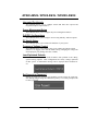
FCC Information and Copyright
This equipment has been tested and found to comply with the limits of a Class
B digital device, pursuant to Part 15 of the FCC Rules. T hese limits are designed
to prov ide reasonable protec tion against harmful interfere nce in a residential
installation. T his equipment generates, uses and can radiate radio frequency
energy and, if not installed and used in accordance with the instructions , may
cause harmful interference to radio communications. There is no guarantee
that i nterference wil l not occur in a particular ins tallatio n.
The ve ndor makes no re presenta tions o r warranties with respec t to the
contents here and specially disclaims any implied warranties of merchantability
o r fi tn es s fo r a ny p u rp os e . F u rt he r t he ve ndo r res e rves t he ri g ht to r ev ise t h is
publication and to make changes to the contents here without obligation to
notify any party beforehand.
D uplica tion of this publicatio n, in pa rt or in whole , is not allowed wi thout first
obtaining the vendor’s approval in writing.
The content of this user’s manual is subject to be changed without notice and
we will not be res ponsible for any mis takes found in this user’s manual. All the
brand and product names are trademarks of their respective companies.

Table of Contents
Chapter 1: Introduction .............................................1
1.1 Before You Start................................................................... 1
1.2 Package Checklist................................................................ 1
1.3 Motherboard Features..........................................................2
1.4 Rear Panel Connectors..........................................................3
1.5 Motherboard Layout for NF500 AM2L / NF500 AM2G............4
1.6 Motherboard Layout for NF500U AM2G................................5
Chapter 2: Hardware Installation ..............................6
2.1 Installing Central Processing Unit (CPU)................................6
2.2 FAN Headers........................................................................ 8
2.3 Installing System Memory...................................................... 9
2.4 Connectors and Slots............................................................11
Chapter 3: Headers & Jumpers Setup......................13
3.1 How to Setup Jumpers..........................................................13
3.2 Detail Settings.....................................................................13
Chapter 4: NVIDIA RAID Functions.........................20
4.1 Operation System................................................................20
4.2 Raid Arrays.........................................................................20
4.3 How RAID Works.................................................................20
Chapter 5: Useful Help ..............................................24
5.1 Driver Installation Note .......................................................24
5.2 Award BIOS Beep Code........................................................25
5.3 Extra Information................................................................25
5.4 Troubleshooting...................................................................27
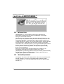
Chapter 6: WarpSpeeder™ .......................................28
6.1 Introduction........................................................................28
6.2 System Requirement............................................................28
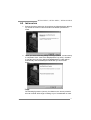
6.3 Installation.........................................................................29
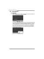
6.4 WarpSpeeder™....................................................................30
Appendencies: SPEC In Other Language ................36
German................................................................................................36
France..................................................................................................38
Italian..................................................................................................40
Spanish................................................................................................42
Portuguese...........................................................................................44
Polish...................................................................................................46
RUSSIAN...............................................................................................48
ARABIC................................................................................................50
JAPANESE............................................................................................52

NF500 AM2G / NF500 AM2L / NF500U AM2G
1
CHAPTER 1: INTRODUCTION
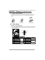
1.1 BEFORE YOU START
Tha nk yo u for choo sing our product. Be fo re you sta rt ins talling the
mo the rboa rd , plea se make sure you fo llo w the instructions be lo w:
Prepare a dry and stable working environment with
s uf ficie nt ligh ting .
Always disconnect the computer from power outlet
be fo re ope ra tion.
Befo re you take the m o the rboa rd ou t f rom a n ti-s ta ti c
bag, ground yourself properly by touching any safely
grounde d appliance, o r use gro unded wrist strap to
remove the static charge.
Avo id tou ch ing the com pone nts o n mo the rboa rd o r the
rear side of the board unless necessary. Hold the boa rd
on the edge , do not try to be nd or flex the boa rd.
Do not leave any unfastened sma ll pa rts inside the
case after installation. Loose parts will cause short
circuits which ma y damage the equipment.
Keep the computer from dangerous area, such as heat
so urce , humid air and wa te r.
1.2 PACKAGE CHECKLIST
FDD Cable X 1
HDD Cable X 1
Se ria l ATA Cab le X 1
Rear I/O Panel for ATX Case X 1
Use r’s Ma nua l X 1
Fully Setup Driver CD X 1
USB 2.0 Cable X1 (optional)
S/P DI F ou t Ca ble X 1 (op tiona l)

Motherboard Manual
2
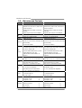
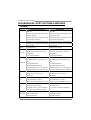
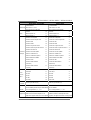
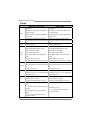
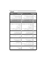
1.3 MOTHERBOARD FEATURES
NF500 AM2G / NF500 AM2L NF500U AM2G
CPU
Socket AM2
AMD Athlon 64 / Athlon 64 FX / Althlon 64 X2 /
Sempron processors
AMD 64 Arc hitecture enables 32 and 64 bit
computing
Supports Hyper Trans port and Cool=n=Quiet
Socket AM2
AMD Athlon 64 / Athlon 64 FX / Althlon 64 X2 /
Sempron processors
AMD 64 Arc hitecture enables 32 and 64 bit
computing
Supports Hyper Trans port and Cool=n=Quiet
FSB
Support HyperTrans port
Supports up to 2GHz Bandwidth
Support HyperTrans port
Supports up to 2GHz Bandwidth
Chipset nVIDIA nForce 500 nVIDIA nForce 500 Ultra
Super I/O
ITE 8716F
Provides the most commonl
y
us e d l e
g
ac
y
Su
p
e
r
I/O functionalit y.
Low Pin Count Interfac e
ITE 8716F
Provides the most commonly used legacy Super
I/O functionalit y.
Low Pin Count Interfac e
Main
Memory
DIMM Slots x 4
Eac h DIMM s upports 256/512MB & 1GB DDR2
Max Memory Capicity 4GB
Dual Channel Mode DDR2 memory module
Supports DDR2 533 / 667 / 800
Registered DIMM and ECC DIMM is not
supported
DIMM Slots x 4
Eac h DIMM s upports 256/512MB & 1GB DDR2
Max Memory Capicity 4GB
Dual Channel Mode DDR2 memory module
Supports DDR2 533 / 667 / 800
Registered DIMM and ECC DIMM is not
supported
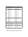
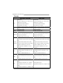
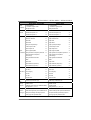
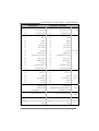
IDE
Integrated IDE Controller
Ultra DMA 33 / 66 / 100 / 133 Bus Master Mode
Integrated IDE Controller
Ultra DMA 33 / 66 / 100 / 133 Bus Master Mode
SA TA
Integrated Serial ATA Controller
Data transfer rates up to 1.5 Gb/s.
SATA Version 1.0 specification compliant.
Integrated Serial ATA Controller
Data transfer rates up to 3.0 Gb/s.
SATA Version 2.0 specification compliant.
LAN
Marvell 88E3016 PHY for NF500 AM2L
10 / 100 Mb/s Auto-Negotiation
Marvell 88E1116 PHY for NF500 AM2G
10 / 100 / 1000 Mb/s A uto-Negotiation
Marvell 88E1116 PHY
10 / 100 / 1000 Mb/s A uto-Negotiation
Sound
C-media C M6501
7. 1 c hannels audio out
USB Audio support
C-media C M6501
7. 1 c hannels audio out
USB Audio support
PCI s lot x4 PCI s lot x4
PCI Express x16 slot x1 PCI Express x16 slot x1 Slots
PCI Express x 1 slot x2 PCI Express x 1 slot x2
Floppy connect or x1 Floppy connect or x1
Printer Port connector x1 Printer Port connector x1
IDE Connector x2 IDE Connector x2
On Board
Connec tor
SA TA Connect or x4 SA TA Connect or x4

NF500 AM2G / NF500 AM2L / NF500U AM2G
3
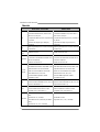
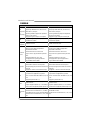
NF500 AM2G / NF500 AM2L NF500U AM2G
Front Panel Connector x1 Front Panel Connector x1
Front Audio Connector x1 Front Audio Connector x1
CD-in Connector x1 CD-in Connector x1
S/PDIF out connector x1 S/PDIF out connector x1
CPU Fan header x1 CPU Fan header x1
Sys tem Fan header x2 Sys tem Fan header x2
CMOS clear header x1 CMOS clear header x1
USB connector x2 USB connector x2
Power Connector (24pin) x1 Power Connector (24pin) x1
Power Connector (4pin) x1 Power Connector (4pin) x1
Back Panel
I/O
PS/2 Keyboard x1
PS/2 Mouse x1
S e ri a l Port x 1
LAN port x1
USB Port x4
Audio Jack x6
PS/2 Keyboard x1
PS/2 Mouse x1
S e ri a l Port x 1
LAN port x1
USB Port x4
Audio Jack x6
Board Siz e 218 x 293 (mm) 218 x 293 (mm)
Special
Features
NVIDIA nTunes
NVIDIA firewall (for NF500 AM2G only)
RAID 0 / 1 / 0+1 s upport
NVIDIA nTunes
NVIDIA firewall
RAID 0 / 1 / 0+1 / 5 support
OS Support
Windows 2K / XP / VISTA
Biostar Reserves the right to add or remove
support for any OS With or without notice.
Windows 2K / XP / VISTA
Biostar Reserves the right to add or remove
support for any OS With or without notice.
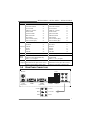
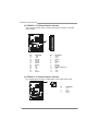
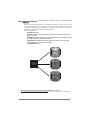
1.4 REAR PANEL CONNECTORS
PS/2
Mouse
PS/2
Keyboard
COM1 COM2
(optional)
USBX2USBX2
LAN
Line In
Line Out
Mic In
Center
Rear
Sid e

Motherboard Manual
4
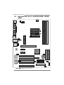
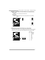
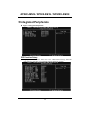
1.5 MOTHERBOARD LAYOUT FOR NF500 AM2L / NF500
AM2G
JKBMS1
JUSB1
JAUDI O2
JUSBLAN1
BIOS
PEX1
_
1
PCI1
FDD1
BAT1
JCOM1
JUSBV 2
JC DIN1
Codec
LAN
J AUDIO F1
JATXPWR2
JPRNT1
PCI2
Su per I/O
J USBV1
JUSB2 JUSB3
DIMMA1
JCMOS1
JPANEL 1
IDE2
JATXPWR1
JCFAN1
J SATA4JSATA3
JSF AN1
JN FAN1
DIMMB1
DIMMB2
DIMMA2
JKBMSV1
PEX1 6
PEX1
_
2
PCI4
PCI3
nVIDIA
nForce500
JSATA2JSATA1
JCOM2
IDE1
JSPDIF_ OUT1
(optional)
No te: represents the 1■
st
pin.

NF500 AM2G / NF500 AM2L / NF500U AM2G
5
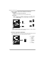
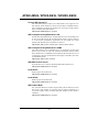
1.6 MOTHERBOARD LAYOUT FOR NF500U AM2G
JKBMS1
JUSB1
JUSBLAN1
BIOS
PEX1
_
1
PCI1
FDD1
BAT1
JCOM1
JUSBV 2
JC DIN1
Codec
LAN
JATXPWR2
JPRNT1
PCI2
Su per I/O
J USBV1
JUSB2 JUSB3
DIMMA1
JCMOS1
JPANEL 1
IDE2
JATXPWR1
JCFAN1
J SATA4JSATA3
JSF AN1
JN FAN1
DIMMB1
DIMMB2
DIMMA2
JKBMSV1
PEX1 6
PEX1
_
2
PCI4
PCI3
nVIDIA
nForce500
Ultra
JSATA2JSATA1
JCOM2
IDE1
JSPDIF_ OUT1
(optional)
JAUDI O2
J AUDIO F1
No te: represents the 1■
st
pin.

Motherboard Manual
6
CHAPTER 2: HARDWARE INSTALLATION
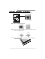
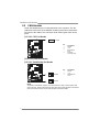
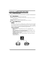
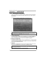
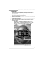
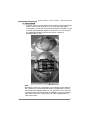
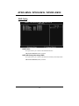
2.1 INSTALLING CENTRAL PROCESSING UNIT (CPU)
Step 1: Remove the socket protection cap.
Step 2: Pull the lever toward direction A from the socket and then raise the
lever up to a 90-degree angle.
Step 3: Look for the white triangle on socket, and the gold triangle on
CPU should point towards this white triangle. The CPU will fit only
in the correct orientation.

NF500 AM2G / NF500 AM2L / NF500U AM2G
7
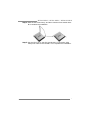
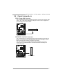
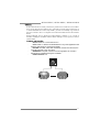
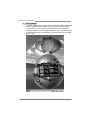
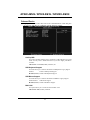
Step 4: Hold the CPU down firmly, and then close the lever toward direct
B to complete the installation.
Step 5: Put the CPU Fan on the CPU and buckle it. Connect the CPU
FAN power cable to the JCFAN1. This completes the installation.

Motherboard Manual
8
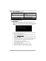
2.2 FAN HEADERS
These fan headers support cooling-fans built in the computer. The fan
cable and connector may be different according to the fan manufacturer.
Connect the fan cable to the connector while matching the black wire to
pin#1.
JCFAN1: CPU Fan Header
Pin
Assignment
1 Ground
2 +12V
3
FAN RPM rate
sense
14
JCFAN1
4 Smart Fan
Control (By Fan)
JSFAN1: System Fan Header
JNFAN1: North Bridge Fan Header
Pin
Assignment
1 Ground
2 +12V
1
13
3
JNFAN1
JSFAN1
3 FAN RPM rate
sense
Note:
The JSFAN1 an d JNFAN1 s up port 3-pin hea d c onn ect or. Wh en c on necti ng with wires
ont o co nnec tors, pleas e n ote th at t he re d wir e is th e positive a nd s ho uld be c onn ect ed t o
pin# 2, a nd th e bl ac k wire is Gro und a nd s hould b e c onn ect ed t o GND.

NF500 AM2G / NF500 AM2L / NF500U AM2G
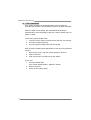
9
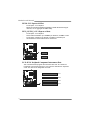
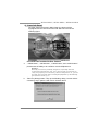
2.3 INSTALLING SYSTEM MEMORY
A. Memory Modules
DIMMA1
DIMMB1
DIMMA2
DIMMB2
1. Unlock a DIMM slot by pressing the retaining clips outward. Align a
DIMM on the slot such that the notch on the DIMM matches the
break on the Slot.
2. Insert the DIMM vertically and firmly into the slot until the retaining
chip snap back in place and the DIMM is properly seated.

Motherboard Manual
10
B. Memory Capacity
DIMM Socket
Location
DDR Module
To tal Memo r y
Size
DIMMA1 256MB/512MB/1024MB
DIMMB1 256MB/512MB/1024MB
DIMMA2 256MB/512MB/1024MB
DIMMB2 256MB/512MB/1024MB
Max is 4GB.
C. Dual Channel Memory installation
To trigger the Dual Channel f unction of the motherboard, the memory module
must meet the following requirements:
Install memory module of the same density in pairs, shown in the f ollowing
table.
Dual Channel Status
DIMMA1
DIMMB1 DIMMA2 DIMMB2
Enabled O O X X
Enabled X X O O
Enabled O O O O
(O means memory installed, X means memory not installed.)
The DRAM bus width of the memory module must be the same (x8 or
x16)

NF500 AM2G / NF500 AM2L / NF500U AM2G
11
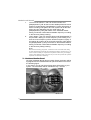
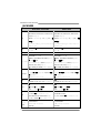
2.4 CONNECTORS AND SLOTS
FDD1: Floppy Disk Connector
The motherboard prov ides a standard floppy disk connector that supports 360K,
720K, 1.2M, 1.44M and 2.88M floppy disk ty pes. This connector supports the
prov ided f loppy drive ribbon cables.
3
4
1
2
33
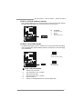
IDE1/IDE2: Hard Disk Connectors
The motherboard has a 32-bit Enhanced PCI IDE Controller that prov ides PIO
Mode 0~4, Bus Master, and Ultra DMA 33/66/100/133 f unctionality. It has two
HDD connectors IDE1 (primary) and IDE2 (secondary).
The IDE connectors can connect a master and a slav e driv e, so you can
connect up to four hard disk drives. The f irst hard drive should always be
connected to IDE1.
21
3940
IDE2IDE1

Motherboard Manual
12
PEX16: PCI-Express x16 Slot
- PCI-Express 1.0a compliant.
- Maximum theoretical realized bandwidth of 4GB/s simultaneously per
direction, f or an aggregate of 8GB/s totally.
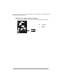
PEX1_1/PEX1_2: PCI-Express x1 slots
- PCI-Express 1.0a compliant.
- Data transf er bandwidth up to 250MB/s per direction; 500MB/s in total.
- PCI-Express supports a raw bit-rate of 2.5Gb/s on the data pins.
- 2X bandwidth ov er the traditional PCI architecture.
PEX1_1
PEX16
PEX1_2
PCI1~PCI4: Peripheral Component Interconnect Slots
This motherboard is equipped with 4 standard PCI slots. PCI stands f or
Peripheral Component Interconnect, and it is a bus standard for expansion
cards. This PCI slot is designated as 32 bits.
PCI3
PCI4
PCI1
PCI2

NF500 AM2G / NF500 AM2L / NF500U AM2G
13
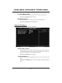
CHAPTER 3: HEADERS & JUMPERS SETUP
3.1 HOW TO SET UP JUMPERS
The illustration shows how to set up jumpers. When the jumper cap is
placed on pins, the jumper is “close”, if not, that means the jumper is
“open”.
Pin opened Pin closed Pin1-2 closed
3.2 DETAIL SETT ING S
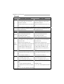
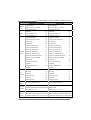
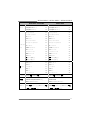
JPANEL1: Front Panel Header
This 16-pin connector includes Power-on, Reset, HDD LED, Power LED, Sleep
button and speaker connection. It allows user to connect the PC case’s f ront
panel switch functions.
1
SLP
PWR
_
LED
On/Off
RST
HLED
SP K
++
+
8
-
-
9
16
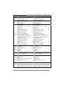
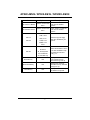
Pin Assignment Function Pin Assignment Function
1 +5V 9 Sleep control
2 N/A 10 Ground
Sleep button
3 N/A 11 N/A N/A
4 Speaker
Speaker
Connector
12 Power LED (+)
5 HDD LED (+) 13 Power LED (+)
6 HDD LED (-)
Hard drive
LED
14 Power LED (-)
Power LED
7 Ground 15 Power button
8 Reset control
Reset button
16 Ground
Power-on button

Motherboard Manual
14
JATXPWR1: ATX Power Source Connector
This connector allows user to connect 24-pin power connector on the ATX
power supply.
113
1224
Pin Assignment Pin Assignment
13 +3.3V 1 +3.3V
14 -12V 2 + 3.3V
15 Gr oun d 3 Groun d
16 PS_ON 4 +5V
17 Gr oun d 5 Groun d
18 Gr oun d 6 + 5V
19 Gr oun d 7 Groun d
20 NC 8 PW_OK
21 +5V 9 Stand b y Volt ag e+5V
22 +5V 10 +12V
23 +5V 11 +12V
24 Gr oun d 12 + 3.3V
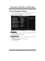
JATXPWR2: ATX Power Source Connector
By connecting this connector, it will provide +12V to CPU power circuit.
Pin
Assignment
1 +12V
2 +12V
3 Ground
1
32
4
4 Ground

NF500 AM2G / NF500 AM2L / NF500U AM2G
15
JKBMSV1: Power Source Selection Headers for Keyboard/Mouse
Pin 1-2 Close:
JKBMSV1: +5V for PS/2 key board and mouse。
Pin 2-3 Close:
JKBMSV1: PS/2 keyboard and mouse are powered with +5V standby
v oltage.
1
3
Pin 1-2 close
1
3
1
3
Pin 2-3 close
JUSB2/JUSB3: Headers for USB 2.0 Ports at Front Panel
This header allows user to connect additional USB cable on the PC f ront panel,
and also can be connected with internal USB devices, like USB card reader.
USB2 / USB3
Pin Assignment
1 +5V (fused)
2 +5V (fused)
3 USB-
4 USB-
5 USB+
6 USB+
7 Ground
8 Ground
9 Key
10 NC
JUSB2 JU SB3
1
2
9
10

Motherboard Manual
16
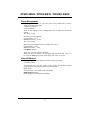
JUSBV1/JUSBV2: Power Source Headers for USB Ports
Pin 1-2 Close:
JUSBV1: +5V for USB ports at JUSBLAN1.
JUSBV2: +5V for USB ports at f ront panel (JUSB2/JUSB3).
Pin 2-3 Close:
JUSBV1: USB ports at JUSBLAN1 are powered by +5V standby voltage.
JUSBV2: USB ports at front panel (JUSB2/JUSB3) are powered by +5V
standby v oltage.
31
1
3
Pin 1-2 close
JUSBV1
JUSBV2
1
1
3
3
3
1
1
3
Pin 2-3 close
Note:
In ord er to s upport this f unction “P ower-On s yst em vi a USB devic e,” “JUSBV1 / JUSB V2”
jump er ca p sh ould be plac ed on Pin 2-3 in di vidu all y.
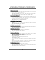
JAUDIOF1: Front Panel Audio Header
This header allows user to connect the front audio output cable with the PC f ront
panel. It will disable the output on back panel audio connectors.
Pin Assignment
1 Mic Left in
2 Ground
3 Mic Right in
4 GPIO
5 Right line in
6 Jack Sense
7 Front Sense
8 Key
9 Left line in
10 Jack Sense
1
9
2
10

NF500 AM2G / NF500 AM2L / NF500U AM2G
17
JCDIN1: CD-ROM Audio-in Connector
This connector allows user to connect the audio source f rom the v ariaty dev ices,
like CD-ROM, DVD-ROM, PCI sound card, PCI TV turner card etc..
Pin
Assignment
1 Left Channel Input
2 Ground
3 Ground
14
4 Right Channel Input
JCMOS1: Clear CMOS Header
By placing the jumper on pin2-3, it allows user to restore the BIOS saf e setting
and the CMOS data, please carefully f ollow the procedures to avoid damaging
the motherboard.
13
Pin 1-2 Close:
Normal Operation (default).
13
13
Pin 2-3 Close:
Clear CMOS data.
※ Clear CMOS Procedures:
1. Remov e AC power line.
2. Set the jumper to “Pin 2-3 close”.
3. Wait f or f ive seconds.
4. Set the jumper to “Pin 1-2 close”.
5. Power on the AC.
6. Reset y our desired password or clear the CMOS data.

Motherboard Manual
18
JSATA1~JSATA4: Serial ATA Connectors
The motherboard has a PCI to SATA Controller with 4 channels SATA interf ace.
Pin
Assignment
1 Ground
2 TX+
3 TX-
4 Ground
5 RX-
6 RX+
JSATA 1 J S ATA2 J SA TA 3 JS ATA 4
1
4
7
7 Ground
JPRNT1: Printer Port Connector
This header allows you to connector printer on the PC.
12
25
Pin Assignment Pin Assignment
1 -Strobe 14 Ground
2 -ALF 15 Data 6
3 Data 0 16 Ground
4 -Error 17 Data 7
5 Data 1 18 Ground
6 -Init 19 -ACK
7 Data 2 20 Ground
8 -Scltin 21 Busy
9 Data 3 22 Ground
10 Ground 23 PE
11 Data 4 24 Ground
12 Ground 25 SCLT
13 Data 5 26 Key
Page is loading ...
Page is loading ...
Page is loading ...
Page is loading ...
Page is loading ...
Page is loading ...
Page is loading ...
Page is loading ...
Page is loading ...
Page is loading ...
Page is loading ...
Page is loading ...
Page is loading ...
Page is loading ...
Page is loading ...
Page is loading ...
Page is loading ...
Page is loading ...
Page is loading ...
Page is loading ...
Page is loading ...
Page is loading ...
Page is loading ...
Page is loading ...
Page is loading ...
Page is loading ...
Page is loading ...
Page is loading ...
Page is loading ...
Page is loading ...
Page is loading ...
Page is loading ...
Page is loading ...
Page is loading ...
Page is loading ...
Page is loading ...
Page is loading ...
Page is loading ...
Page is loading ...
Page is loading ...
Page is loading ...
Page is loading ...
Page is loading ...
Page is loading ...
Page is loading ...
Page is loading ...
Page is loading ...
Page is loading ...
Page is loading ...
Page is loading ...
Page is loading ...
Page is loading ...
Page is loading ...
Page is loading ...
Page is loading ...
Page is loading ...
Page is loading ...
Page is loading ...
Page is loading ...
Page is loading ...
Page is loading ...
Page is loading ...
Page is loading ...
Page is loading ...
Page is loading ...
Page is loading ...
Page is loading ...
Page is loading ...
Page is loading ...
Page is loading ...
Page is loading ...
-
 1
1
-
 2
2
-
 3
3
-
 4
4
-
 5
5
-
 6
6
-
 7
7
-
 8
8
-
 9
9
-
 10
10
-
 11
11
-
 12
12
-
 13
13
-
 14
14
-
 15
15
-
 16
16
-
 17
17
-
 18
18
-
 19
19
-
 20
20
-
 21
21
-
 22
22
-
 23
23
-
 24
24
-
 25
25
-
 26
26
-
 27
27
-
 28
28
-
 29
29
-
 30
30
-
 31
31
-
 32
32
-
 33
33
-
 34
34
-
 35
35
-
 36
36
-
 37
37
-
 38
38
-
 39
39
-
 40
40
-
 41
41
-
 42
42
-
 43
43
-
 44
44
-
 45
45
-
 46
46
-
 47
47
-
 48
48
-
 49
49
-
 50
50
-
 51
51
-
 52
52
-
 53
53
-
 54
54
-
 55
55
-
 56
56
-
 57
57
-
 58
58
-
 59
59
-
 60
60
-
 61
61
-
 62
62
-
 63
63
-
 64
64
-
 65
65
-
 66
66
-
 67
67
-
 68
68
-
 69
69
-
 70
70
-
 71
71
-
 72
72
-
 73
73
-
 74
74
-
 75
75
-
 76
76
-
 77
77
-
 78
78
-
 79
79
-
 80
80
-
 81
81
-
 82
82
-
 83
83
-
 84
84
-
 85
85
-
 86
86
-
 87
87
-
 88
88
-
 89
89
-
 90
90
-
 91
91


Biostar NF500 AM2G Owner's manual
- Category
- Motherboards
- Type
- Owner's manual
Ask a question and I''ll find the answer in the document
Finding information in a document is now easier with AI
Related papers
-
Biostar N4SLI-A9 Bios Setup Manual
-
-
-
-
-
-
-
-
-
Other documents
-
Mach P4MST-890 Setup Manual
-
Dell 56193617 Datasheet
-
Nvidia nForce 570 SLI User manual
-
Albatron K8X250GB PRO User manual
-
-
-
Sapling 50 Watt Power Supply Installation guide
-
-
-
PC CHIPS M789CG (V3.0A) User guide