Sony HVR-S270E User manual

Category
Camcorders
Type
User manual

This manual is also suitable for

3-280-852-13(1)
© 2008 Sony Corporation
http://www.sony.net/
Printed on 70% or more recycled paper
using VOC (Volatile Organic Compound)
-free vegetable oil based ink.
Printed in Japan
GB
Digital HD Video Camera Recorder
Digital HD Video
Camera Recorder
Operating Guide
Before operating the unit, please read this manual thoroughly,
and retain it for future reference
HVR-S270E/S270P
2
Read this first
Before operating this unit, please read this
manual thoroughly, and retain it for future
reference.
Types of cassette you can use in your
camcorder
Your camcorder is capable of recording in
HDV, DVCAM and DV formats.
When recording in HDV/DV format, Sony
recommends that you use standard size DV
cassettes or mini DV cassettes.
When recording in DVCAM format, Sony
recommends that you use standard size
DVCAM cassettes or mini DVCAM
cassettes. Your camcorder does not support
the Cassette Memory function (p. 107).
The HDV format
Digital high-definition (HD) video signals
are recorded and played back on a DV
format cassette.
• HDV signals are compressed in MPEG2
format, which is adopted in BS (broadcast
satellite) digital and terrestrial digital
HDTV broadcastings and in Blu-ray disc
recorders.
Types of “Memory Stick” you can use
in your camcorder
You can use any “Memory Stick” that has
the following markings.
“Memory Stick Duo”
(This size can be used with your
camcorder.)
“Memory Stick”
(You cannot use it in your camcorder.)
b Notes
You cannot use any type of memory card
except “Memory Stick Duo.”
“Memory Stick PRO Duo” can be used
only with “Memory Stick PRO
compatible equipment.
Do not attach a label or the like on a
“Memory Stick Duo” or a “Memory Stick
Duo” Adaptor.
When using a “Memory Stick Duo” with
“Memory Stick” compatible equipment,
insert the “Memory Stick Duo” into the
“Memory Stick Duo” Adaptor.
Notes on use
3
Using the camcorder
Do not hold the camcorder by the
following part.
b Notes
The camcorder is not dustproof, dripproof
or waterproof.
See “About handling of your camcorder
(p. 113).
Do not connect cables to your camcorder
w
ith t
heir terminals placed the wrong
way. Squeezing the terminals into your
camcorder's jacks may damage them or
results in a malfunction of your
camcorder.
About menu items, LCD panel,
viewfinder, and lens
A menu item that is grayed out is not
available under the current recording or
playback conditions.
The LCD screen and the viewfinder are
m
anu
factured using extremely high-
precision technology, so over 99.99% of
the pixels are operational for effective
use. However, there may be some tiny
black points and/or bright points (white,
red, blue, or green in color) that appear
constantly on the LCD screen and the
viewfinder. These points are normal
results of the manufacturing process and
do not affect the recording in any way.
Do not expose your camcorder’s
viewfinder, lens, or LCD screen to the
sun or strong light source for extended
periods.
Intense light sources, especially the sun
will converge on the viewfinder or lens
and damage the internal parts of your
camcorder. Avoid sunlight or other strong
light sources when storing your
camcorder. Protect this device by always
closing the lens cover or by placing it in
its bag when not in use.
On recording
Before starting to record, test the
recording function to make sure the
picture and sound are recorded without
any problems.
LCD panel
Battery pack
Microphone or
Microphone holder
Viewfinder
Lens hood
Memory
Recording Unit
Black point
White, red, blue or green points
Continued ,
4
• Compensation for the contents of
recordings cannot be provided, even if
recording or playback is not possible due
to a malfunction of the camcorder, storage
media, etc.
TV color systems differ depending on the
co
untries/
regions. To view your
recordings on a TV, you need a PAL
system-based TV.
• Television programs, films, video tapes,
an
d othe
r materials may be copyrighted.
Unauthorized recording of such materials
may be contrary to the copyright laws.
• Because of the way that the image device
(CM
OS se
nsor) reads out image signals,
the subjects passing by the frame rapidly
might appear crooked depending on the
recording conditions. This phenomenon
may be notable in displays having high
motion resolution.
• Because of the way that the image device
(CM
OS se
nsor) reads out image signals,
the following phenomena may occur. The
phenomena can be reduced by adjusting
the shutter speed.
Horizontal lines appear on the screen during
recording under fluorescent lights.
Images on the screen look horizontally
divided when a subject is lighted with
flashlight.
On playing back HDV tapes on other
devices
A tape recorded in the HDV format cannot
be played back on a device that is not
compatible with the HDV format.
Check the contents of tapes by playing
t
hem ba
ck on this camcorder prior to
playing them back on other devices.
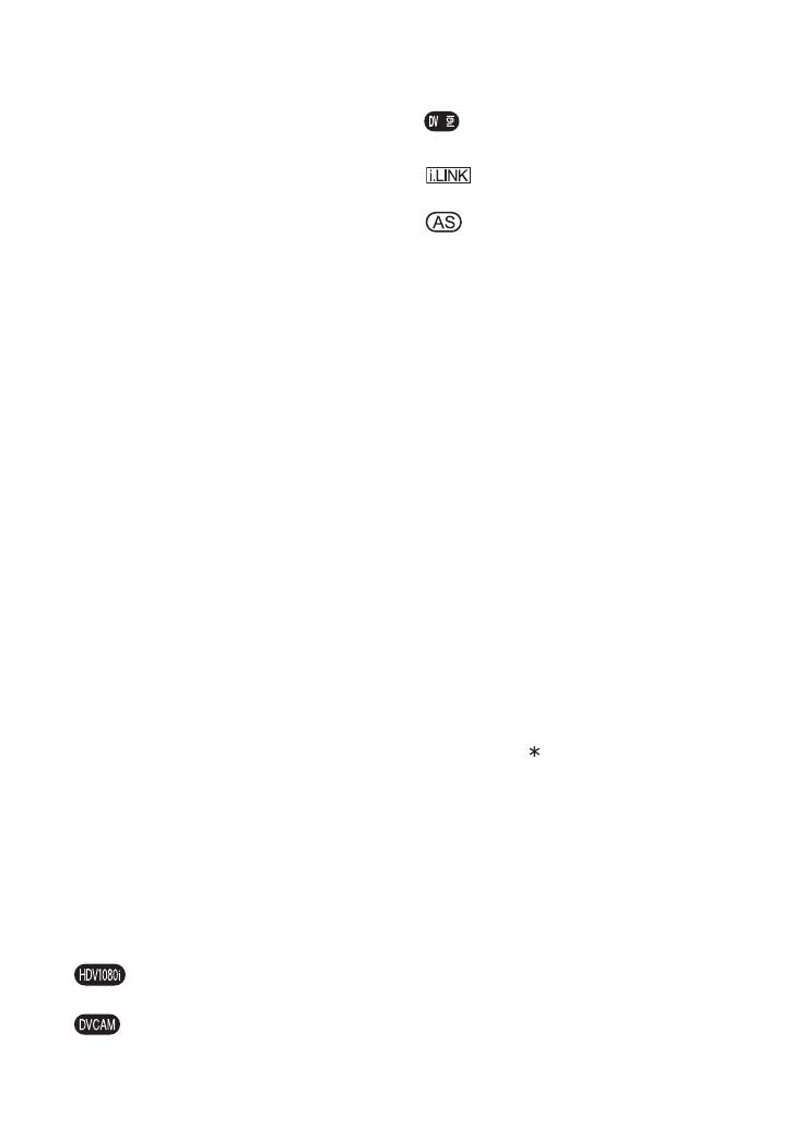
Notes on the icons used in this
manua
l
Features available for the HDV
format only.
Features available for the DVCAM
format only.
Features available for the DV SP
format only.
The function that can be used when
i.LINK cable is connected.
The function that can be assigned to
an ASSIGN button.
About this manual
The images of the LCD screen and the
viewfinder used in this manual for
illustration purposes are captured using a
digital still camera, and therefore may
appear different.
The on-screen displays in each local
l
anguage
are used for illustrating the
operating procedures. Change the screen
language before using your camcorder if
necessary (p. 22).
Design and specifications of recording
m
edia an
d other accessories are subject to
change without notice.
About the Carl Zeiss lens
Your camcorder is equipped with a Carl
Zeiss lens, which was developed jointly by
Carl Zeiss, in Germany, and Sony
Corporation, and produces superior images.
It adopts the MTF measurement system for
video cameras and offers a quality typical
of a Carl Zeiss lens. Also, the lens for your
camcorder is T -coated to suppress
unwanted reflections and faithfully
re
produce c
olors.
MTF= Modulation Transfer Function. The
nu
mber va
lue indicates the amount of light
from a subject coming into the lens.
Read this first (Continued)
5
Table of Contents
Read this first ...........................................................................................2
Step 1: Checking supplied items ..............................................................8
Step 2:
Attaching the supplied items ........................................................9
Step 3: Preparing a power supply ..........................................................16
Step 4: Turning the power on and holding your camcorder properly .....18
Step 5: Adjusting the viewfinder and LCD panel ....................................19
Step 6: Setting the date and time ...........................................................21
Changing the language setting .......................................................... 22
Step 7: Inserting a tape or a “Memory Stick Duo” ..................................23
Recording ..............................................................................................26
Changing the settings of your camcorder recordings .............................30
Adjusting the zoom ............................................................................. 30
Adjusting the focus manually.............................................................. 31
Adjusting the exposure ....................................................................... 33
Adjusting to natural color
(White balance)................................................................................... 35
Adjusting the black balance ............................................................... 37
Customizing the picture quality (Picture profile) ................................. 37
Adjusting the volume .......................................................................... 46
Assigning the functions to the ASSIGN buttons .....................................49
Recording an index signal .................................................................. 50
Reviewing the most recently recorded scenes (Rec review).............. 51
Searching for the last scene of the most recent recording
(End search) ....................................................................................... 51
Playing back the most recently recorded movies
(Last scene review) ............................................................................. 51
Using the Shot transition ........................................................................52
Marking focal point on the screen (Focus marking) ...............................55
Playback .................................................................................................56
Changing/checking the settings in your camcorder ................................59
Changing the screen .......................................................................... 59
Displaying recording data (Data code) .............................................. 59
Displaying the settings in your camcorder (Status check) ................. 60
Connecting a monitor or a TV ................................................................61
Getting Started
Recording/Playback
Continued ,
6
Using the menu items ........................................................... 63
Menu items ............................................................................................ 65
(CAMERA SET) menu .................................................................... 68
Settings to adjust your camcorder to the recording conditions (GAIN SETUP/
BACK LIGHT/STEADYSHOT, etc.)
(AUDIO SET) menu ........................................................................ 75
Settings for the audio recording (HDV 2CH/4CH/XLR SET, etc.)
(DISPLAY SET) menu .................................................................... 77
Display settings of the display and the viewfinder (MARKER/VF B.LIGHT/DISP
OUTPUT, etc.)
(IN/OUT REC) menu ...................................................................... 81
Recording settings, input and output settings (REC FORMAT/HDV PROGRE./
VIDEO OUT/EXT REC CTRL, etc.)
(TC/UB SET) menu ....................................................................... 85
(TC PRESET/UB PRESET/TC LINK, etc.)
(MEMORY SET) menu .................................................................... 87
Settings for the “Memory Stick Duo” (ALL ERASE/FORMAT, etc.)
(OTHERS) menu ............................................................................ 89
Settings while recording on a tape or other basic settings (QUICK REC/BEEP,
etc.)
Recording pictures from a VCR ............................................................ 92
Copying movies on a tape to a computer .............................................. 94
Troubleshooting ..................................................................................... 97
Warning indicators and messages ....................................................... 106
Using the Menu
Dubbing/Editing
Troubleshooting
Table of Contents (Continued)
7
Maintenance and precautions ..............................................................107
HDV format and recording/playback ................................................ 107
Compatibility of the DVCAM/DV formats........................................... 108
About the “Memory Stick” ................................................................. 110
About i.LINK...................................................................................... 111
About x.v.Color ................................................................................. 112
About handling of your camcorder ................................................... 113
Specifications .......................................................................................117
Identifying parts and controls ...............................................................121
Indicators for the LCD screen and viewfinder ......................................128
Index .....................................................................................................132
Additional Information
Quick Reference
8
Getting Started
Step 1: Checking supplied items
Make sure that you have following items
supplied with your camcorder.
The number in the parentheses indicates the
nu
mber of
that item supplied.
A cassette tape and a “Memory Stick Duo” are
not included. See pages 2, 107 and 110 for types
of cassette tape and “Memory Stick Duo” that
you can us
e on your camcorder.
Carl Zeiss lens (VCL-412BWS) (1) (p. 9)
This lens is pre-mounted.
Memory Recording Unit (HVR-MRC1) (1)
(p. 14),
i.LINK Cradle (HVRA-CR1) (1) (p. 15)
Lens hood with lens cover (1) (p. 13)
This lens hood is pre-mounted.
Large eyecup (1) (p. 19)
Wind Screen (1), Microphone (ECM-XM1)
(1) (p. 12)
Accessory shoe kit (Accessory shoe (1),
Accessory shoe plate (1), screws (4))
(p. 121)
Shoulder belt (1) (p. 13)
Lens mount cap (1) (p. 127),
Rear lens cap (1) (p. 127)
Test chart for flange focal length
adjustment (1) (p. 10)
CD-ROM “Manuals for Digital HD Video
Camera Recorder” (1)
Operating Guide (This manual) (1)
9
Getting Started
Step 2: Attaching the supplied items
Make sure to turn off the POWER switch of
your camcorder before mounting the lens.
Refer to the manuals provided with the lens
for
de
tails on the proper handling of the
lens.
1 P
ush the lens locking lever D up and
remove the lens or the lens mount cap
from the lens mount.
2 Align the center slot in the lens mount
wit
h the center pin on the lens, and
insert the lens into the mount.
3 While holding the lens in place, push
the
lens locking lever D down to
mount the lens.
b Notes
If the lens is not properly locked, it may come
off when in use, which may cause a serious
problem. Make sure that the lens is securely
locked. Sony recommends that you set the lens
securing tab C as illustrated.
1 Push the lens locking lever D up and
remove the lens or the lens mount cap
from the lens mount.
2 Align the center slot in the lens mount
wit
h the center pin on the lens, and
insert the lens into the mount.
3 W
hile holding the lens in place, push
the len
s locking lever D down to
mount the lens.
4 Connect the lens cable to the LENS jack
A.
5 Push the lens cable in the cable holder
B.
b Notes
Use a lens mount adaptor suitable for your lens.
1/3" bayonet mount lens
You can mount the lens without an adaptor.
2/3" bayonet mount lens
Use a Fujinon ACM-17.
A focal length is twice as that without the
adaptor.
1/2" bayonet mount lens
Use a Fujinon ACM-12.
A focal length is 1.3 times as that without the
adaptor.
SONY 1/2" bayonet mount lens
Use a Fujinon ACM-19.
A focal length is 1.3 times as that without the
adaptor.
Your
lens performance is not guaranteed.
When you mount a lens other than a Carl Zeiss
lens, you
cannot use the following menu items.
Even you set those menu items, the settings do
not take effect.
Mounting the lens
Mounting the Carl Zeiss lens
Mounting non-Carl Zeiss lens
For the lens with the lens cable (12 Pin)
AF ASSIST
ASSIGN BTN
CAMERA
ASSIGN#
FOCUS
FOCUS INFNTY
FOCUS MACRO
ONE PUSH AF
ASSIGN BTN
LENS
L1
L2
FLANGE BACK
FOCUS DISP
FOCUS MACRO
Continued ,
10
# shows the ASSIGN BTN number.
* If your lens does not have a zoom display
function,
the zoom position is not displayed on
the screen.
**Your camcorder does not display the extender
indicator when you us
e the extender function of
the lens.
# shows the ASSIGN BTN number.
If the lens is not properly locked, it may come
off when i
n use, which may cause a serious
problem. Make sure that the lens is securely
locked. Sony recommends that you set the lens
securing tab C as illustrated.
Press the REC START/STOP button on the
hand
le to record when using a lens that does not
have a lens cable.
z Tips
When you attach a non-Carl Zeiss lens, Sony
recommends that you adjust the black balance
with the iris closed before recording. (p. 37)
You need to adjust the flange focal length
(the distance from the lens flange to the
plane of the image along the optical axis)
when you have changed lenses.
z Tips
Your camcorder can store flange focal length
data for ten different Carl Zeiss lenses (VCL-
412BWS/VCL-308BWS. If you remount the
lens after you have mounted ten different lenses
and adjusted their flange focal length, you need
to adjust the flange focal length for the lens even
for the Carl Zeiss lens whose flange focal length
has been adjusted.
HANDLE ZOOM
SHOT TRANSITION
STEADYSHOT
S.TRANS/F.MARK
ZOOM DISPLAY*
Extender indicator**
For the lens without the lens cable (12 Pin)
AF ASSIST
ASSIGN BTN
CAMERA
ASSIGN#
FOCUS
FOCUS INFNTY
FOCUS MACRO
ONE PUSH AF
ASSIGN BTN
LENS
L1
L2
RET
AT IRIS LMT
CAM DATA DSP (Iris value)
FLANGE BACK
FOCUS DISP
FOCUS MACRO
HANDLE ZOOM
SHOT TRANSITION
STEADYSHOT
S.TRANS/F.MARK
ZOOM DISPLAY
For the lens with the lens cable (12 Pin)
Adjusting the flange focal length (for
Carl Zeiss lens)
Step 2: Attaching the supplied items (Continued)
11
Getting Started
Adjusting the flange focal length
automatically
1 Set the CAMERA MODE switch F to
MANUAL.
2 S
et the IRIS switch E to MAN.
3
Set the gain to 0dB with the gain switch
H
.
If you have not changed the gain switch
setting from the default, set the gain
switch H to L.
Make sure that the AGC switch is set to
OFF.
4 S
et the shutter speed to automatic
adjust
ment mode (p. 35).
5 F
ully open the aperture with the iris ring
I.
6 P
lace the flange focal length adjustment
te
st ch
art A about 2-3 meters (7-10
feet) away.
Adjust the lighting or the ND filter B
so t
hat a subj
ect is properly lighted.
7 S
et the ZOOM switch J to SER
VO.
8
Select [AUTO ADJUST] in [FLANGE
BACK] of (CAMERA SET) menu
(p. 74).
9
Select [YES] with the SEL/PUSH
EXEC dial
G
.
The flange focal length adjustment starts
and [EXECUTING] appears on the screen.
When the adjustment is completed,
[Compl
eted.] appears on the screen.
If the adjustment fails, [Could not adjust.]
appe
ars on the screen. Try the adjustment
again.
Adjusting the flange focal length
manually
1
Perform steps
1
through
6
of
"Adjusting the flange focal length
automatically."
2
Set the ZOOM switch
J
to MANUAL.
3
Select [MANU ADJUST] in [FLANGE
BACK] of (CAMERA SET) menu.
4
Select [YES] with the SEL/PUSH
EXEC dial
G
.
5
Turn the zoom ring
D
fully to the
telephoto side.
6
Turn the focus ring
C
until the subject
comes in focus, then press the SEL/
PUSH EXEC dial
G
.
7
Turn the zoom ring
D
fully to the wide
angle side.
8
Turn the focus ring
C
until the subject
comes in focus, then press the SEL/
PUSH EXEC dial
G
.
T
Continued ,
12
When the adjustment is completed,
[Completed.] appears on the screen.
If the adjustment fails, [Could not adjust.]
appears on the screen. Try the adjustment again.
z Tips
You can check the focusing easily if you do the
following before adjusting the focal length.
Set the PEAKING switch to ON (p. 32).
Press the ASSIGN button to which
[EXP.
FOCUS] is assigned (p. 49).
If the adjustment fails, confirm the following.
A bright subject is not within the view.
The ND filter switch does not stop at halfway
between two posit
ions.
1
Attach the wind screen B to the
supplied microphone A.
2
Place the microphone A in the
microphone holder C with the
model name facing upward, close
the cover, and shut the clamp.
3
Connect the plug of the
microphone to the AUDIO INPUT1
(L) jack D.
Push the plug in the jack until it is
securely locked.
4
Put the microphone cable into the
cable holder E.
5
Select the channel with the REC
CH SELECT switch F.
See p. 46 for details.
z Tips
See page 46 for adjusting the volume.
Set the INPUT1/2/3/4 switch for the jack
connect
ed to the microphone to MIC+48V.
When you connect a device that supports the
+48V power source to any of the INPUT jacks,
set the respective INPUT switch to MIC prior to
connecting the device. When you disconnect the
device, set the respective INPUT switch to MIC
first, then disconnect it.
Attaching the supplied microphone
REC CH SELECT
2CH MODE
IN1
CH1 CH2
IN2
IN4
IN3
Put the cable in the outer cable holder.
Step 2: Attaching the supplied items (Continued)
13
Getting Started
Align the marks on the lens hood to
those on the camcorder, and turn the
lens hood in the direction of the
arrow 2.
To remove the Lens hood with lens
cover
Turn the lens hood in the opposite direction
to the arrow
2
in the illustration while
pressing the PUSH (lens hood release)
button.
z Tips
If you attach or remove a 72mm (2 7/8 in.) PL
filter or MC protector, remove the lens hood
with lens cover.
To open or close the shutter of the
Lens hood with lens cover
Move the lens cover lever up or down to
open or close the lens cover.
1
Fit one of the clips to a shoulder
strap fitting.
Attaching the lens hood with lens
cover
PUSH (lens hood release) button
Attaching the shoulder strap
Move the lens cover lever to OPEN to
open the lens cover, and move the lever
to CLOSE to close the lens cover.
Clip
Pull up the strap to lock the fitting.
Continued ,
14
2
Fit the other clip to the shoulder
strap fitting on the other side of
the grip in the same way.
To remove the shoulder strap
Attach the Memory Recording Unit to your
camcorder as illustrated after inserting your
CompactFlash Card into it.
For details, refer to the Operating
I
nst
ructions of the Memory Recording Unit
on the CD-ROM.
b Notes
You cannot use the
HDV/DV jack when the
Memory Recording Unit is attached to your
camcorder
.
We recommend using Sony CompactFlash
Cards with your Memory Recording Unit.
When you use non-Sony CompactFlash
Cards, data may be recorded incorrectly.
When you use non-Sony CompactFlash
C
ards
, we recommend that you test them
beforehand as follows.
1
Format the CompactFlash Card with the
Memory Recording Unit.
2
Record at least 20 clips of about 10
seconds each in HDV recording mode.
3
If you have nonlinear editing software,
load the files into it and check whether
you can edit the data correctly.
Pull in the direction of the
arrow while pressing here.
Attaching Memory Recording Unit
Using non-Sony CompactFlash Cards
HDV/DV jack (6-pin)
Step 2: Attaching the supplied items (Continued)
15
Getting Started
To remove the Memory Recording
Unit
Slide the unit upward while pushing the
RELEASE lever of the Memory Recording
Unit downward.
To attach the Memory Recording Unit
to the i.LINK Cradle
Attach the Memory Recording Unit to the
i.LINK Cradle as illustrated.
To remove the Memory Recording
Unit from the i.LINK Cradle
Slide the unit upward while pushing the
RELEASE lever of the Memory Recording
Unit downward.
z Tips
Refer to the operating instructions of HVR-
MRC1 on the supplied CD-ROM for details on
the i.LINK Cradle.
16
Step 3: Preparing a power supply
The following power supplies are
recommended for your camcorder.
BP-GL65/GL95/L60S/L80S Lithium-ion
Battery P
ack
• AC power using the AC-550, AC-DN2,
AC
-DN10 AC
Adaptor
Approximate operating time (min.) when
you use
a fully charged battery pack.
Before use, charge the battery pack with a
charger suitable for each battery.
All times are measured under following
conditions.
when recording on both tape and Memory
Recording Unit (HVR-MRC1)
when using the microphone (ECM-XM1)
when recording continuously
when using the viewfinder with the LCD
panel closed
F
or details on charging procedure, refer to the
battery charger operation manual.
b Notes
A warm battery pack may not be able to be fully
recharged.
When you set [BATTERY TYPE] appropriately
for your battery, approximate remaining battery
capacity is displayed on the screen. The
displayed approximate remaining battery
capacity may slightly differ from that indicated
by the indicator on your battery (p. 91).
To attach the battery pack
1
Press the battery pack against the back
of the camcorder, aligning the line on
the side of the battery pack with the
matching line on the camcorder.
2
Slide the battery pack down until its
“LOCK” arrow points at the matching
line on the camcorder.
To detach the battery pack
b Notes
During recording, playback, and loading/
unloading a tape, be careful never to remove the
battery pack.
Make sure to turn the camcorder off before
changing the battery (except when using an AC-
550 and an AC-DN2/DN10 AC Adaptor
together).
Using a battery pack
Model name HDV DVCAM (DV)
BP-GL65 240 255
BP-GL95 370 385
BP-L60S 215 230
BP-L80S 295 310
LOCK
LOCK
“LOCK” arrow
Line on the
camcorder
LOCK
Holding the
button in, pull
the battery pack
up.
17
Getting Started
To use the AC-550 AC Adaptor
Connect the camcorder to the AC power
supply through an AC-550 AC Adaptor as
shown in the following figure, and turn the
POWER switch of the AC-550 on.
To use the AC-DN10 AC Adaptor
Mount an AC-DN10 on the camcorder in
the same way as a battery pack, then
connect to the AC power supply.
The AC-DN10 can supply up to 100 W of
po
wer.
When t
he battery pack is becoming
exhaust
ed, you can perform battery
replacement without causing a break to the
camcorder operation by using an AC
Adaptor.
1
Turn the AC-550 AC Adaptor on.
2
Connect an AC-550 AC Adaptor to an
AC power source, then connect it to the
DC IN 12V connector of the camcorder
(p. 17).
The power source switches
au
tomati
cally from the battery pack to
the AC Adaptor connected to the DC IN
12V connector.
b Notes
There may be some noise on the video
signal at the time of power source
switching.
3
Replace the battery pack with a fully
charged one.
Using an AC Adaptor
Avoiding breaks in operation due
to an exhausted battery
L
O
C
K
Power switch on
to an AC power
source
DC OUT
AC
Adaptor
AC-550
DC output cable
(supplied with the
AC-550)
DC IN 12V
to an AC
power
source
18
Step 4: Turning the power on and holding your
camcorder properly
To record or play, set the CAMERA/VCR
switch to respective positions.
When you use your camcorder for the first
ti
me, [
CLOCK SET] screen appears (p. 21).
1
Set the POWER switch to ON, and
set the CAMERA/VCR switch.
CAMERA:
To record pictures.
VCR:
To play or edit pictures.
b Notes
The current date and time appears on the LCD
screen for a few seconds when you turn on your
camcorder once you set the date and time
([CLOCK SET], p. 21).
2
Hold the camcorder properly.
3
Ensure a good grip, then fasten
the grip belt.
To turn off the power
Set the POWER switch to OFF.
b Notes
If warning messages appear on the screen,
follow the instructions.
L
O
C
K
POWER switch
CAMERA/VCR switch
CAMERA
VCR
POWER
ON OFF
19
Getting Started
Step 5: Adjusting the viewfinder and LCD panel
To attach the large eyecup
To attach the supplied large eyecup, stretch
it slightly and align it with the eyecup
groove in the viewfinder. You can attach
the large eyecup facing either the right or
left side.
To adjust the viewfinder position
To adjust the viewfinder left-to-right
position, loosen the left-to-right fixing ring.
To adjust the front-to-back position, loosen
the front-to-back position locking knob.
To adjust the eyepiece focus
First focus the image with the lens, then
adjust the viewfinder lens adjustment lever
to get the clearest viewfinder image for
your eyesight.
To adjust the image detail
Set the PEAKING switch to ON.
The detail of the viewfinder image is
enhanced, which helps you to focus the
image.
The viewfinder
LOCK
Large eyecup
(supplied)
Align the protrusion
on the eyecup with
the mark on the eye
piece.
Viewfinder left-to-right
position fixing ring
Viewfinder front-to-back
position locking knob
Eyepiece
focusing knob
PEAKING
switch
20
To adjust the brightness
Set the brightness in [VF B.LIGHT] of
(DISPLAY SET) menu (p. 80).
b Notes
You may see primary colors shimmering in the
viewfinder when you move your eye line. This
is not a malfunction. The shimmering colors
will not be recorded on the recording media.
b Notes
When you set the VIDEO OUT switch to LCD,
video signals cannot be output from the VIDEO
OUT jack or S VIDEO jack. To output the video
signals from the VIDEO OUT jack or S VIDEO
jack, set the VIDEO OUT switch to
COMPOSITE. With this setting, images are not
displayed on the screen.
z Tips
You can use the LCD panel for recording mirror
image. You will see a mirror image on the LCD
screen but the image will be recorded in a
normal image.
Because the LCD panel on your camcorder is a
full-s
creen display, bottom of the screen may
look distorted, such as horizontal lines on the
screen. This does not affect on your images
recorded on your CompactFlash Card or tape.
To adjust the brightness
Adjust the LCD brightness with the - LCD
BRIGHT + buttons. You can turns on and
off the LCD backlight by pressing the
DISPLAY button.
The LCD panel
MEMORY
DELETE
DISPLAY LCD BRIGHT
INDEX
-
+
-
+
PLAY
2180
degrees
(max.)
290
degrees
(max.)
DISPLAY button
1180 degrees (max.)
- LCD BRIGHT +
buttons
Set the VIDEO
OUT switch to
LCD.
Step 5: Adjusting the viewfinder and LCD panel (Continued)
  • Page 1 1
  • Page 2 2
  • Page 3 3
  • Page 4 4
  • Page 5 5
  • Page 6 6
  • Page 7 7
  • Page 8 8
  • Page 9 9
  • Page 10 10
  • Page 11 11
  • Page 12 12
  • Page 13 13
  • Page 14 14
  • Page 15 15
  • Page 16 16
  • Page 17 17
  • Page 18 18
  • Page 19 19
  • Page 20 20
  • Page 21 21
  • Page 22 22
  • Page 23 23
  • Page 24 24
  • Page 25 25
  • Page 26 26
  • Page 27 27
  • Page 28 28
  • Page 29 29
  • Page 30 30
  • Page 31 31
  • Page 32 32
  • Page 33 33
  • Page 34 34
  • Page 35 35
  • Page 36 36
  • Page 37 37
  • Page 38 38
  • Page 39 39
  • Page 40 40
  • Page 41 41
  • Page 42 42
  • Page 43 43
  • Page 44 44
  • Page 45 45
  • Page 46 46
  • Page 47 47
  • Page 48 48
  • Page 49 49
  • Page 50 50
  • Page 51 51
  • Page 52 52
  • Page 53 53
  • Page 54 54
  • Page 55 55
  • Page 56 56
  • Page 57 57
  • Page 58 58
  • Page 59 59
  • Page 60 60
  • Page 61 61
  • Page 62 62
  • Page 63 63
  • Page 64 64
  • Page 65 65
  • Page 66 66
  • Page 67 67
  • Page 68 68
  • Page 69 69
  • Page 70 70
  • Page 71 71
  • Page 72 72
  • Page 73 73
  • Page 74 74
  • Page 75 75
  • Page 76 76
  • Page 77 77
  • Page 78 78
  • Page 79 79
  • Page 80 80
  • Page 81 81
  • Page 82 82
  • Page 83 83
  • Page 84 84
  • Page 85 85
  • Page 86 86
  • Page 87 87
  • Page 88 88
  • Page 89 89
  • Page 90 90
  • Page 91 91
  • Page 92 92
  • Page 93 93
  • Page 94 94
  • Page 95 95
  • Page 96 96
  • Page 97 97
  • Page 98 98
  • Page 99 99
  • Page 100 100
  • Page 101 101
  • Page 102 102
  • Page 103 103
  • Page 104 104
  • Page 105 105
  • Page 106 106
  • Page 107 107
  • Page 108 108
  • Page 109 109
  • Page 110 110
  • Page 111 111
  • Page 112 112
  • Page 113 113
  • Page 114 114
  • Page 115 115
  • Page 116 116
  • Page 117 117
  • Page 118 118
  • Page 119 119
  • Page 120 120
  • Page 121 121
  • Page 122 122
  • Page 123 123
  • Page 124 124
  • Page 125 125
  • Page 126 126
  • Page 127 127
  • Page 128 128
  • Page 129 129
  • Page 130 130
  • Page 131 131
  • Page 132 132
  • Page 133 133
  • Page 134 134
  • Page 135 135

Sony HVR-S270E User manual

Category
Camcorders
Type
User manual
This manual is also suitable for

Ask a question and I''ll find the answer in the document

Finding information in a document is now easier with AI