Garmin GPS 400W Reference guide

Category
Radar detectors
Type
Reference guide
© 2012 GARMIN Corporation
GARMIN International, Inc.
1200 East 151
st
Street, Olathe, Kansas 66062, U.S.A.
Tel. 913/397.8200 or 866/739.5687
Fax 913/397.8282
Garmin AT, Inc.
2345 Turner Rd., S.E., Salem, Oregon 97302, U.S.A.
Tel. 503/581.8101 or 800/525.6726
Fax. 503/364.2138
Garmin (Europe) Ltd.
Liberty House, Bulls Copse Road, Hounsdown Business Park,
Southhampton, SO40 9RB, U.K.
Tel. +44 (0) 870 850 1243
Fax +44 (0) 238 052 4004
GARMIN Corporation
No. 68, Jangshu 2
nd
Road, Shijr, Taipei County, Taiwan
Tel. 886/2.2642.9199
Fax 886/2.2642.9099
www.garmin.com
https://fl y.garmin.com/fl y-garmin
October 2012 190-00356-36 Rev B
190-00356-36 Rev B
1
GNS 400W/500W Series SW V5.00
Upgrade Supplement
This supplement provides information regarding new features of software version 5.00
for 400W/500W Series units.
The Pilot’s Guide and Garmin Displays Addendum have been revised for SW Version 5.00.
GNS 400W/500W Series Pilot’s Guide & Reference,
(Garmin P/N 190-00356-00 or 190-00357-00, respectively) Rev H or later
GNS 400W/500W Series Quick References,
(Garmin P/N 190-00356-01 or 190-00357-01, respectively) Rev G or later
GNS 400W/500W Series Garmin Optional Displays Addendum
(Garmin P/N 190-00356-30) Rev I or later
NOTE: The combination of the following documents is equivalent to the
Pilot’s Guide revisions listed above:
GNS 400W/500W Series SW Version 5.00 Upgrade Supplement
(Garmin P/N 190-0356-36)
GNS 400W/500W Series SW Version 4.00 Upgrade Supplement
(Garmin P/N 190-0356-35)
GNS 400W/500W Series SW Version 3.30 Upgrade Supplement
(Garmin P/N 190-0356-34)
GNS 400W/500W Series SW Version 3.20 Upgrade Supplement
(Garmin P/N 190-0356-33)
GNS 400W/500W Series SW Version 3.00 Upgrade Supplement
(Garmin P/N 190-0356-32)
GNS 400W/500W Series Pilot’s Guide & Reference (any Revision)
GNS 400W/500W Series Garmin Optional Displays Addendum
(any Revision)
GNS 400W/500W Series Display Interfaces Addendum (any Revision)
Current documents are available at www.garmin.com for free download.
Printed copies may be purchased by contacting Garmin Customer Support.
2
190- 00356-36 Rev B
400W & 500W Series Pilot’s Guides & Quick References
Warnings and Messages
WARNING: Do not use data link weather information for maneuvering in, near, or
around areas of hazardous weather. Information contained within data link weather
products may not accurately depict current weather conditions.
WARNING: Do not use the indicated data link weather product age to determine
the age of the weather information shown by the data link weather product. Due
to time delays inherent in gathering and processing weather data for data link
transmission, the weather information shown by the data link weather product may
be signifi cantly older than the indicated weather product age.
TAWS Alerting
TAWS Alerting has been improved to reduce nuisance alerts. During installation, the
installer will confi gure the runway type and lengths that are appropriate for the installed
aircraft.
Manual GTN Crossfi ll
NOTE: The databases of the 400/500 series and the 400W/500W are incompatible,
so you may not mix systems.
NOTE: Manual GTN Crossfi ll requires the 400W/500W series unit to have the same
Jeppesen NavData® database cycle number as the GTN unit.
NOTE: Crossfi ll and Manual GTN Crossfi ll can not be confi gured to be present at
the same time. The chosen feature is confi gured by the installer for your installation.
NOTE: Ensure that the GTN unit has Auto GNS Crossfi ll enabled.
The Manual GTN Crossfi ll Function allows the GNS 400W/500W series unit to
manually send all User waypoints to the connected GTN unit or receive informa-
tion from a GTN unit.
The information received from the GTN unit includes the following:
Active Waypoint Leg
Active Flight Plan
Direct-To Waypoint
Suspend/OBS Status
Manual GTN Crossfi ll is a feature that will keep the GNS system in sync with a
ight plan that is being used on the GTN system. The GTN will not automatically
keep its fl ight plan in sync with changes made on the GNS system. Essentially, the
crossfi ll feature is “one way” – from the GTN to the GNS.
This page intentionally left blank
30
190- 00356-36 Rev B
3
190- 00356-36 Rev B
The GTN systems support a variety of procedure leg types that the GNS systems
do not support. As such, it is normal and expected that the fl ight plan leg that is
displayed on the GNS system will not always match the fl ight plan leg on the GTN
system. Departure, arrival and approach procedures often contain leg types that
the GNS does not support. The GNS typically “skips” over these leg types and pro-
vides no guidance. Guidance may be available on the GTN but not on the GNS in
these cases. The GNS will fl y the procedure as it normally would if Crossfi ll were
not active. Once a leg type is reached that is supported on both the GTN and GNS
systems, the systems will automatically sync to the same leg.
Waypoint names longer than six characters, or duplicates, sent from the GTN unit
to the GNS unit will replace some characters with a “+” sign, while leaving signifi cant
characters to aid in identifi cation (such as, USR003 becomes US+003).
To Enable Flight Plan Crossfi ll from the GTN Unit
1. From the Default NAV Page, Active Flight Plan page, or the User
Waypoint page press MENU. Highlight “GTN Crossfi ll?” and then
press ENT.
OR
2. On the Aux Flight Planning page scroll down to “Manual GTN Crossfi ll”
with the large or small right knob, and then press ENT.
4
190- 00356-36 Rev B
3. With the Link fi eld highlighted, turn the small right knob to show
“Enabled”, and then press ENT. This enables the GNS unit to receive
ight plan information from the GTN unit.
CAUTION: The user is required to always verify each fl ight plan leg prior to navigat-
ing with the GNS unit when Manual GTN Crossfi ll is active.
NOTE: If the user manually alters the fl ight plan on the GNS unit, the systems will
not crossfi ll until the pilot activates the feature again on the GNS unit.
To Transfer GNS User Waypoints to the GTN Unit
1. Continuing from the steps above, turn the large right knob to highlight
“Initiate Transfer?.
2. Press ENT. The 400W/500W-series unit’s User waypoints will be sent
to the GTN unit.
This page intentionally left blank
29
190- 00356-36 Rev B
This page intentionally left blank
28
190- 00356-36 Rev B
5
190- 00356-36 Rev B
400W/500W Series Garmin Optional Displays
Addendum
Software version 5.00, or later, supports the features provided by the GDL 88, in both
the 400W and 500W series units. Full details are available in the GNS 400W/500W
Series Garmin Optional Displays Addendum (Garmin P/N 190-00356-30 Rev I).
Canadian Weather
Canadian METARs and TAFs are now shown where available.
Garmin GDL 88 Interface
Introduction
The GDL 88 is a remote-mounted product that contains a 978 MHz Universal
Transceiver (UAT) and a 1090 MHz receiver. The GDL 88 will transmit ownship
ADS-B data via the UAT data link. It will receive data from other UAT and 1090ES
equipped aircraft, as well as Flight Information Service Broadcast (FIS-B) weather.
The received data may be output to an appropriate display.
6
190- 00356-36 Rev B
FIS-B Weather
Flight Information Services (FIS) Description
The Flight Information Services (FIS) function is capable of displaying text and
graphic weather information with GDL 88 installations. The current version of FIS
is FIS-B and no subscription for the services is required with the GDL 88.
The FIS-B Function is a graphic weather display capable of displaying graphical
weather information on UAT equipped installations. Graphical data is overlaid on
the map indicating the precipitation (rain, hail, or mixed) detected by ground based
radar for a specifi c area. The colors indicating increasing levels of precipitation pro-
gresses from green for light precipitation to red for heavy precipitation. Precipita-
tion data is color coded as follows:
FIS-B Weather Legend
A cyan checkerboard pattern indicates that no data is available for that area.
When weather data is received, the airborne system will display Region NEXRAD
data for 30 minutes and CONUS NEXRAD for 60 minutes. After the expiration time
the data will be removed, “NXRD: N/A” will be displayed.
The FIS-B Function is based on a ground-to-air data link and requires that the
appropriate ground systems are broadcasting weather data and the aircraft is within
reception range of the Ground Broadcast Transceiver (GBT ). Low fl ying aircraft may
not receive FIS-B weather updates due to terrain blocking the GBT broadcast.
27
190- 00356-36 Rev B
Traffi c Watch
If your 400W/500W-series unit is connected to other equipment providing traf-
c alert information (e.g., L3 SKYWATCH™ or RYAN TCAD), a traffi c alert pop-up
is provided to display traffi c information. This allows you to monitor traffi c condi-
tions from ANY page and quickly identify traffi c hazards.
Traffi c
Watch
Window
Traffi c
Information
1. In Aux mode, select “Data Field Confi guration” from the Setup 1 Page.
2. Turn the small right knob to select the desired data fi eld option. The
following options are available:
3. Press ENT to accept the selection.
26
190- 00356-36 Rev B
3. With TCAD GND Mode selected, pressing ENT toggles between Enter
and Exit GND mode.
4. Select Setup? and press ENT to reach the Setup page.
5. Select Self Test? and press ENT to start the Self Test process.
Ryan TCAD Setup
1. From the Nav mode Traffi c page, press the MENU key. Turn the small
right knob to highlight “Setup?” and then press ENT.
2. The RYAN TCAD Setup screen will now be displayed and the Baro
Pressure selection will be activated for selection. Turn the small knob
to select a numeric value and turn the large right to move the cursor
and then press ENT to save the selected value.
2. The Ground/Field Elevation value is now activated for selection. Turn
the small knob to select a numeric value and turn the large right to
move the cursor and then press ENT to save the selected value.
3. The Volume fi eld is now activated for selection. Turn the small knob
to select a numeric value and turn the large right to move the cursor
and then press ENT to save the selected value.
7
190- 00356-36 Rev B
UAT FIS-B Graphic Weather Info with the GDL 88
The ground system determines the weather coverage area and extent of data that
is transmitted by each ground station. The GDL 88 can provide weather informa-
tion from multiple sources.
Text Display
FIS -B text messages are available on the text display and include METARs and
TAFs . Messages are composed of four parts: message type, location, time , and mes-
sage body.
NEXRAD Description
WSR-88D weather surveillance radar or NEXRAD (NEXt generation RADar) is
a Doppler radar system that has greatly improved the detection of meteorological
events such as thunderstorms , tornadoes , and hurricanes . An extensive network
of NEXRAD stations provides almost complete radar coverage of the continental
United States, Alaska, and Hawaii. The unobstructed range of each NEXRAD is 124
nautical miles. The update rate is 2.5 minutes for Region NEXRAD and 15 minutes
for CONUS NEXRAD.
NEXRAD Abnormalities
There are possible abnormalities regarding displayed NEXRAD images. Some,
but not all, causes of abnormal displayed information include:
• Ground Clutter
• Strobes and spurious radar data
• Sun strobes, when the radar antenna points directly at the sun
• Military aircraft deploy metallic dust which can cause alterations in radar scans
• Interference from buildings or mountains , which may cause shadows
• Scheduled maintenance may put a radar off-line
8
190- 00356-36 Rev B
NEXRAD Limitations
Certain limitations exist regarding the NEXRAD radar displays. Some, but not
all, are listed for the user’s awareness:
NEXRAD base refl ectivity does not provide suffi cient information to determine
cloud layers or precipitation characteristics (hail vs. rain , etc).
NEXRAD base refl ectivity is sampled at the minimum antenna elevation angle.
An individual NEXRAD site cannot depict high altitude storms at close ranges,
and has no information about storms directly over the site.
The resolution of displayed Region NEXRAD data is approximately two kilo-
meters and the resolution of displayed CONUS NEXRAD data is approximately
10 kilometers. Therefore, when zoomed in on the display, each square block is
two kilometers (1.08 NM) or 10 kilometers (5.4 NM) on a side. The intensity
level refl ected by the square will be the highest level sampled within the area
covered by each block.
NEXRAD Intensity
Colors are used to identify the different NEXRAD echo intensities (refl ectivity )
measured in dBZ (decibels of Z). “Refl ectivity” is the amount of transmitted power
returned to the radar receiver. Refl ectivity (designated by the letter Z) covers a wide
range of signals (from very weak to very strong). So, a more convenient number for
calculations and comparison, a decibel (or logarithmic) scale (dBZ), is used. The
dBZ values increase as the strength of the signal returned to the radar increases.
There are six gradations for precipitation intensity.
NEXRAD Options
When enabled, NEXRAD precipitation intensity information is shown. Compos-
ite data from all of the NEXRAD radar sites in the United States for the selected area
is shown. This data is composed of the maximum refl ectivity from the individual
radar sweeps. The display of the information is color-coded to indicate the weather
level severity. Information about which sites are operational or off-line is also avail-
able (see coverage below). Refer to the legend for a description of the color code.
The NEXRAD option has selections of REGION NEXRAD or CONUS NEXRAD.
REGION NEXRAD shows NEXRAD radar information for the region around the
aircraft location. CONUS NEXRAD shows NEXRAD radar information for the con-
tinental United States.
25
190- 00356-36 Rev B
vided. The call sign will be sent as “VFR.” To enable Anonymous Mode, the Squawk
Code must be set to the VFR code (based on the GDL 88 confi guration) and the
Anonymous Mode must be armed.
RYAN TCAD
Ryan TCAD is a system that provides audio and visual alerts for traffi c near your
aircraft. The information from this system can be interfaced through the GDL 88 to
the GNS 400W/500W series. Operating instructions and details on the modes of
operation are described in the Ryan TCAD operator’s handbooks.
Setting Altitude Display Mode
The GDL 88 TCAD has four altitude display modes: Normal (±2,700 feet, Above
(-2,700 feet to +9,000 feet), Below (-9,000 feet to +2,700 feet), and Unrestricted
(±9,900 feet). The GDL 88 continues to track up to 30 intruder aircraft within its
maximum surveillance range, regardless of the altitude display mode selected.
The selected altitude display mode is displayed in the upper left-hand corner of
the Traffi c page.
1. While viewing the Traffi c page, press the small right knob to activate
the cursor and highlight the current mode. Turn the small right knob
to cycle through the options.
2. With each turn of the knob, the screen changes to display the traffi c
detected within the selected altitude display range. The 400W/500W
Series screen also displays unrestricted traffi c (UNR) having a maximum
range available.
3. Press ENT to confi rm and save the selected value.
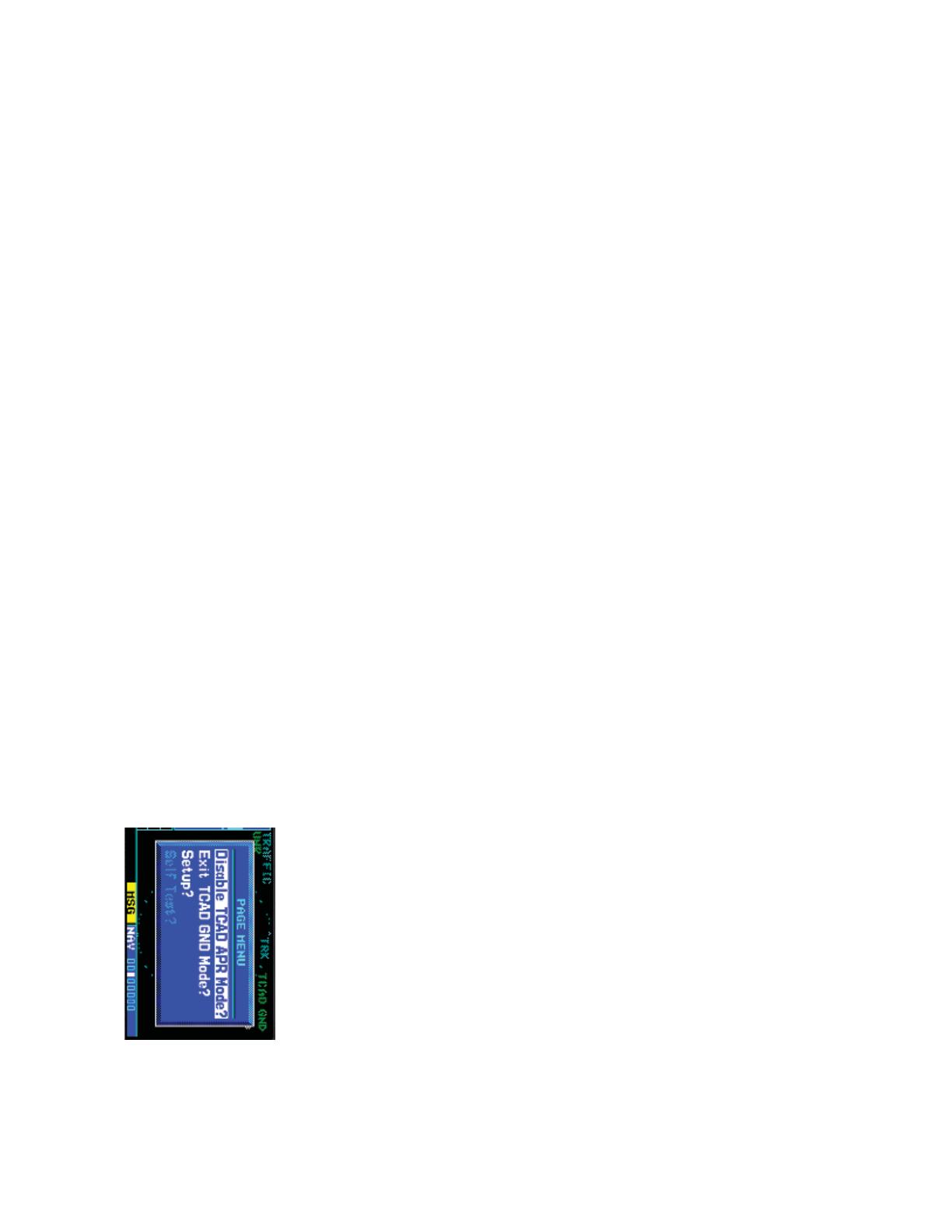
TCAD Traffi c Page Menu
1. Press MENU to display the page menu. Turn the small or large right
knob to highlight the desired choice of commands to send to the Ryan
TCAD.
2. With the TCAD APR Mode selected, pressing ENT toggles between
Enabled and Disabled.
24
190- 00356-36 Rev B
Failure Response
Errors indicated by a “FAILED” message on the screen prevent continued use
of the GDL 88 Series unit. If the GDL 88 is confi gured (not integrated with TCAD/
TCAS system) and reports an invalid heading, invalid track, and valid GPS position,
“UNAVAIL” will be displayed in the center of the page. See the GDL 88 Status page
for information on Failure Response.
GDL 88 STATUS page, lists some of the problems with the GDL 88,
which might cause the failure.
GDL 88 STATUS page menu allows Arming/Disarming Anon mode
and turning Pressure Altitude Reporting On/Off.
One of the features of the optional GDL 88 is to send Automatic Dependent Sur-
veillance – Broadcast (ADS-B ) position reports for enhanced situational awareness.
The GDL 88 is a remote-mount module that communicates with panel-mounted
avionics for traffi c and weather display, and for equipment control. The GDL 88
receives position information from the GTN GPS receiver. The display and control
of the information sent depends on the equipment installation and confi guration by
the installer. Some installations allow control by the pilot of the information sent,
while others do not.
The Anonymous Mode, when armed, will replace the Flight ID with a temporary
randomized number for privacy while the position information will still be pro-
9
190- 00356-36 Rev B
To select CONUS NEXRAD, REGION NEXRAD, or graphic METARs
on the Nav Weather page:
1. In NAV mode, turn the small right knob to the FIS-B Weather page.
2. Press the small right knob to activate selection.
3. Turn the small right knob to select CONUS NEXRAD, REGION NEXRAD,
or METARs.
4. P
ress the small right knob to save the displayed selection.
To select CONUS NEXRAD or REGION NEXRAD on the Nav Map
pages:
1. In NAV mode, turn the small right knob to one of the Nav Map pages
(Nav pages 1 or 2).
2. Press the MENU key.
3. Turn the small right knob to select Display CONUS NEXRAD or Display
RGN NEXRAD.
4. P
ress the ENT key to save the displayed selection.
Continental US NEXRAD (CONUS)
The Display CONUS NEXRAD selection shows NEXRAD radar information for
the entire continental United States.
NEXRAD Coverage
Aircraft Position
NEXRAD Weather
Outside of NEXRAD
Coverage
Weather Page With CONUS NEXRAD Displayed
Region NEXRAD
The Display RGN NEXRAD selection shows NEXRAD radar information for the
region around the aircraft location. By covering a smaller region than is shown in
the CONUS display, Region NEXRAD will be provide a higher resolution display of
the weather data.
10
190- 00356-36 Rev B
Outside of NEXRAD
Coverage
NEXRAD Coverage
Aircraft Position
Weather Page With Region NEXRAD Displayed
NEXRAD Weather
Select Region
NEXRAD, CONUS
NEXRAD, or METAR
METARs
When enabled, graphic METARs (METeorological Aviation Reports) are shown
as colored fl ags at airports that provide METAR reports in Nav mode. Refer to the
Legend for a description of the color code. The update rate is every fi ve minutes
and there is a 90 minute expiration time. When a GDL 88 is installed, two weather-
related pages are added to the “airport” pages in the WPT page group: the Textual
METAR page and the TAF page. If both the GDL 88 and GDL 69 are installed, the
Textual METAR and TAF pages show the most recent data as well as the data source
(FIS-B or XM).
To view Textual METARs:
1. In WPT mode, turn the small right knob to the FIS-B Weather METAR
page.
2. Press the small right knob to activate the cursor.
3. Turn the small or large right knob to scroll through the page of
Textual METARs.
23
190- 00356-36 Rev B
Highlighting Traffi c Data Using Map Panning
Another map page function is panning, which allows you to move the map
beyond its current limits without adjusting the map scale. When you select the pan-
ning function—by pressing the small right knob—a target pointer flashes on the
map display. A window also appears at the top of the map display showing the lati-
tude/longitude position of the pointer, plus the bearing and distance to the pointer
from your present position.
When the target pointer is placed on traffi c,
the traffi c range and altitude separation are
displayed.
To select the panning function and pan the map display:
1. Press the small right knob to activate the panning target pointer.
2. Turn the small right knob clockwise to move up, or turn it counter-
clockwise to move down.
3. Turn the large right knob clockwise to move right, or turn it counter-
clockwise to move left.
4. To cancel the panning function and return to your present position,
press the small right knob.
When the target pointer is placed on traffi c, the traffi c range and altitude separa-
tion are displayed. The traffi c is identifi ed as:
TA: Traffi c Advisory, PA: Proximity Advisory,
TRFC: Other Traffi c
22
190- 00356-36 Rev B
NOTE: Proximity Advisories (PA) are displayed as solid white diamonds
(may be confi gured as cyan). The GDL 88 shows these PAs as “other”
(hollow diamonds). PAs are defi ned as traffi c within the 6.0 NM range, with
± 1200 feet of altitude separation, and not a traffi c advisory (TA).
From the Map Page, you can display traffi c in a thumbnail format in any of the
top three data fi elds (top four fi elds on the 500W Series) on the right side of the
Map Page.
When a Traffi c Advisory is active, the “Traffi c” banner is displayed in the lower right corner
of the Map Page.
To display Thumbnail Traffi c on the Map Page
1. Turn the small right knob to select the Map Page.
2. Press MENU to display the Page Menu.
3. Turn the small right knob to select “Change Fields?” and press ENT.
4. Select one of the top three fi elds (top four fi elds on the 500W Series).
Select TRFC from the Select Field Type List and press ENT. Note that
the thumbnail range defaults to 6 NM and cannot be changed.
11
190- 00356-36 Rev B
Terminal Area Forecast (TAF)
TAF (Terminal Aerodrome or Area Forecast) is the standard format for 24-hour
weather forecasts. A TAF typically forecasts signifi cant weather changes, temporary
changes, probable changes, and expected changes in weather conditions.
To view TAFs:
1. In WPT mode, turn the small right knob to the TAF page.
2. Press the small right knob to activate the cursor.
3. Turn the small or large right knob to scroll through the page of TAFs.
12
190- 00356-36 Rev B
Traffi c
Introduction
The GDL 88 transceivers are remote-mount modules that interface with panel-
mount avionics to display traffi c and weather, and for equipment control. Enhanced
situational awareness and ATC surveillance are achieved through Automatic Depen-
dent Surveillance – Broadcast (ADS-B) position reports sent and received from the
GDL 88.
There are four versions of the GDL 88:
GDL 88 = no WAAS, one antenna
GDL 88/D = no WAAS, two antennas (Diversity)
GDL 88 w/WAAS = WAAS, one antenna
GDL 88/D w/WAAS = WAAS, two antennas (Diversity)
The GDL 88 has the ability to receive broadcast services provided by the FAA
– including Flight Information Services-Broadcast (FIS-B) weather and Traffi c Infor-
mation Services Broadcasts (TIS-B) traffi c – when the aircraft is within range of
UAT base stations. The 1090 MHz ADS-B receiver included in the GDL 88 Datalink
Transceiver products provides a complete traffi c picture of all equipped aircraft,
without regard to proximity to a ground station, and without limitations imposed
by the ground-based services.
ADS ON – in green
ADS INC – in green*
ADS TEST – in white
ADS OFF – in white
ADS N/A – in white**
ADS FAIL – in yellow
* ADS INC - ADS Incomplete. When the GDL 88 reports to the GNS that “TIS-B/ADS-R Service
Status is unavailable”, the GNS sets the status to “ADS INC.”
* if the GDL 88 with TCAD/TCAS is confi gured on the GNS and the GDL 88 reports invalid
heading, invalid track, and a valid GPS position, the ADS state shall display as N/A (not
available).
The Garmin GDL 88 receives traffi c information from an Extended Squitter-capa-
ble transponder, such as the Garmin GTX 32/327/33/330. The GDL 88 series using
TIS-B enhances fl ight crew situational awareness by displaying traffi c information
for transponder-equipped aircraft. The GDL 88 also provides visual and aural traffi c
alerts including voice announcements to assist in visually acquiring traffi c.
21
190- 00356-36 Rev B
Confi guring Traffi c Data on the Map Page
Traffi c is only displayed on the Map Page if aircraft heading data is available.
When a TA is detected and the Traffi c page is not being viewed, the Traffi c Pop-Up
will be displayed. Pressing the CLR key will close the Pop-Up and a “TRAFFIC”
banner will be shown on the Map page.
Selections for confi guring traffi c data are made from the Map Setup Menu on the Map
Page.
From the Map Page, you can display traffi c in a thumbnail format in any of the
top three data fi elds (top four fi elds on the 500W Series) on the right side of the
Map Page.
To confi gure traffi c on the Map Page:
1. Turn the small right knob to select the Map Page.
2. Press MENU to display the Page Menu. Turn the small right knob to
select “Setup Map?” and press ENT.
3. The fl ashing cursor highlights the GROUP eld. Turn the small right
knob to select Traffi c and press ENT.
4. Turn the large right knob to select the desired Traffi c Mode option.
Turn the small right knob to select the desired option and press ENT.
Repeat the step for Traffi c Symbol and Traffi c Label.
5. Return to the Map Page by pressing CLR.
Traffi c mode allows the operator to choose which traffi c is displayed (all traffi c,
traffi c and proximity advisories, or traffi c advisories only). The traffi c symbol is the
symbol used to depict the type of traffi c:
20
190- 00356-36 Rev B
Traffi c Alert Pop-Up
NOTE: The Traffi c Alert Pop-Up is displayed only in normal operating
conditions when the aircraft is airborne and there is no terrain alerting or
dead reckoning alert.
NOTE: The Traffi c Alert Pop-Up is disabled when the aircraft ground
speed is less than 30 knots or when an approach is active, unless the unit
is confi gured for helicopter operation as noted by the helicopter ownship
icon.
NOTE: GDL 88 series unit data is only displayed on the Map Page if suitable
aircraft heading data is available. See the Garmin 400W or 500W Series
Installation Manuals available at your authorized Garmin service center
for details.
Traffi c Page Display Range
You can change the display range on the Traffi c Page at any time.
1. Press the RNG Key to cycle through the following range options (Inner
Ring/Outer Ring):
None/1 NM, 1/2 NM, 2/6 NM, 6/12 NM, 12/24 NM, and 24/40 NM.
13
190- 00356-36 Rev B
The Standby Screen appears when the
GDL 88 passes the power-up test.
NOTE: when the system is in standby, the
GDL 88 does not transmit, interrogate, or
track intruders aircraft.
Traffi c Information Services-Broadcast (TIS-B)
TIS-B is a ground-based uplink of air traffi c radar targets. TIS-B is an advisory-
only application designed to enhance the pilot’s visual acquisition of surrounding
traffi c and increase situational awareness. The GDL 88 will receive TIS-B from the
UAT and 1090 datalinks when in range of a ground station.
Automatic Dependent Surveillance-Broadcast (ADS-B)
ADS-B technology is an important part of the FAAs Next Generation Air Trans-
portation System (NextGen), allowing for enhanced safety, effi ciency, and the ability
of the system to handle greater numbers of aircraft. ADS-B In allows a properly-
equipped aircraft to access FAA broadcast services such as TIS-B and FIS-B. With
ADS-B Out, the avionics transmit an aircraft’s precise location, as well as specifi c
information about that aircraft, to ground stations and other aircraft equipped with
978 MHz ADS-B technology.
Traffi c Display Management
The GDL 88 will assemble traffi c reports for targets received from the follow-
ing traffi c interfaces: UAT TIS-B uplink, 1090 TIS-B uplink, UAT ADS-B messages,
1090 ADS-B messages, and from an external traffi c source, if installed. The GDL 88
will determine which traffi c reports will be sent to the connected display. The GDL
88 can send a maximum of 30 targets. The GNS can display up to eight targets.
14
190- 00356-36 Rev B
Power-up Self-Test
Check for the following test criteria on the Traffi c Page during power-up:
1. If the GDL 88 series unit passes the power-up test and your aircraft
has both a squat switch and is on the ground, the Standby Screen is
displayed.
2. If the GDL 88 series unit passes the power-up test and your aircraft
has both a squat switch and is airborne, the Traffi c Page is displayed
on the 6 NM display range and in the normal altitude display mode.
3. If the GDL 88 series unit passes the power-up test and your aircraft
does not have a squat switch, the Standby Screen is displayed.
4. If the display indicates that the GDL 88 series unit has failed, please
refer to the failure response section in the Pilot’s Guide for actions to
take.
NOTE: The FAILED message occurs when the system detects an error and
prohibits further traffi c display operation as long as this message stays on
the screen.
User-initiated Test
NOTE: A user-initiated test can only be performed when in standby or
failed mode.
In addition to the power-up test, the GDL 88 series unit performs a continuous
self-test. This continuous self-test is performed several times per minute. A user-
initiated test of the GDL 88 series unit interface can also be performed.
To perform a user-initiated test:
1. In the Nav page group, turn the small right knob to select the Traffi c
Page.
2. From the Traffi c Page, press MENU to display the Page Menu.
3. Turn the small right knob to select “Self Test?” and press ENT.
19
190- 00356-36 Rev B
ADS ON – in green
ADS INC – in green
ADS TEST – in white
ADS OFF – in white
ADS N/A – in white
ADS FAIL – in yellow
TCAD modes:
TCAD STBY – in white
TCAD OPER – in green
TCAD FAIL – in yellow
TCAD TEST – in white
TCAD APR – in green
TCAD GND – in green
Traffi c With GDL 88 With TCAD
If GDL 88 is confi gured (not integrated with TCAD/TCAS system) and it reports
invalid heading, invalid track, and valid GPS position, “UNAVAIL” will be displayed
in the center of the page.
Traffi c With GDL 88 and Invalid Heading or Track
If either TCAS or ADS is in failed state, valid data may still be available. Intruders
may still be displayed from the operational device.
The yellow FAIL indication is shown in the center of the screen only when both
ADS and TCAS/TCAD have failed.
Traffi c Alert Pop-Up
When the unit is not on the traffi c page and a traffi c threat is imminent, the Traf-
c Alert Pop-Up is displayed. The Traffi c Alert Pop-Up shows a small map and can
display the Traffi c Page (if the user presses ENT) or return to the previous page (if
the user presses CLR).
18
190- 00356-36 Rev B
+2,700 ft
Drawing Not to Scale
Normal (NRM)
Below (BLW)
+2,700 ft
-9,900 ft
Above (ABV)
0 ft
+9,900 ft
Unrestricted (UNR)
0 ft
-2,700 ft
-9,000 ft
+9,000 ft
Altitude Display Modes
Traffi c Target
Track Vector
ADS ON – in green
ADS INC – in green
ADS TEST – in white
ADS OFF – in white
ADS N/A – in white
ADS FAIL – in yellow
Traffi c With GDL 88
The vectors extending from the traffi c targets display how the traffi c target is
moving relative to the ground. The vector length is fi xed and has no correlation to the
speed of the target.
ADS ON – in green
ADS INC – in green
ADS TEST – in white
ADS OFF – in white
ADS N/A – in white
ADS FAIL – in yellow
TCAS/TCAD modes:
TCAS STBY – in white
TCAS OPER – in green
TCAS FAIL – in yellow
TCAS TEST – in white
Traffi c With GDL 88 With TCAS
15
190- 00356-36 Rev B
Altitude Display Mode
There are four altitude display modes: Normal (±2,700 feet, Above (-2,700 feet
to +9,000 feet), Below (-9,000 feet to +2,700 feet), and Unrestricted (±9,900 feet).
The selected altitude display mode is displayed in the upper left-hand corner of the
Traffi c page. The GDL 88 continues to track up to 30 intruder aircraft within its
maximum surveillance range, regardless of the altitude display mode selected. The
GNS unit will display up to eight intruders.
The name of the selected altitude display mode (ABV: look up,
NRM: normal, BLW: look down, or UNR: unrestricted) is displayed
in the upper left-hand corner of the Traffi c Screen.
To change the Altitude Display Mode:
1. From the Traffi c Page, turn the cursor on, highlight the current mode
and turn the small right knob to cycle through the options.
2. With each turn of the knob, the screen changes to display the traffi c
detected within the selected altitude display range.
3. Note that confi rmation is not required. The mode is changed immediately
when using the small right knob. Turn the cursor off when selection
is made.
Switching Between Standby and Operating Modes
The unit must be in operating mode for traffi c to be displayed. The ability to
switch out of standby into operating mode on the ground is especially useful for
scanning the airspace around the airport before takeoff.
To switch into Operating Mode:
To set the mode to Operating when the GDL 88 is not connected to either TCAD
or TCAS:
1. Press the cursor knob and highlight ADS OFF”. Turn the small right
knob to select ADS ON?”.
16
190- 00356-36 Rev B
2. Press ENT to confi rm and place the GDL 88 in operating mode.
3. Press the cursor knob to exit the menu option and view the updated
mode.
To set the mode to Operate on the GNS units connected to GDL 88 with TCAD or
TCAS, the pilot will need to place both ADS and TCAS/TCAD in operating modes.
1. Press the cursor knob and highlight “TCAD STBY” or “TCAS STBY”.
Turn the small right knob to select “TCAS OPER?” or “TCAD OPER?”.
2. Press ENT to confi rm.
3. Change the ADS to Operational mode, if it is not already set. Turn the
small right knob to select ADS ON?”.
4. Press ENT to confi rm.
5. Press the cursor knob to exit the menu option and view the updated
mode.
NOTE: The GDL 88 series unit switches out of standby into the 6 NM
display range. If your aircraft has a squat switch and you do not manually
switch out of standby, the GDL 88 series unit will automatically switch out
of standby 8 to 10 seconds after takeoff.
To switch into Standby Mode:
To set the mode to Standby when GDL 88 is not connected to either TCAD or
TCAS:
1. Press the cursor knob and highlight ADS ON”. Turn the small right
knob to select ADS OFF?”.
2. Press ENT to confi rm and place the GDL 88 series unit in Standby mode.
3. Press the cursor knob to exit the menu option and view the updated
mode.
To set the mode to Standby on the GNS units connected to GDL 88 with TCAD or
TCAS, the pilot will need to place both ADS and TCAS/TCAD to the Standby modes.
1. Press the cursor knob and highlight “TCAD OPER” or “TCAS OPER”.
Turn the small right knob to select “TCAS STBY?” or “TCAD STBY?”.
2. Press ENT to confi rm.
3. Change the ADS to Standby mode, if it is not already set. Turn the small
right knob to select ADS OFF?”.
4. Press ENT to confi rm.
5. Press the cursor knob to exit the menu option and view the updated
mode.
17
190- 00356-36 Rev B
NOTE: If your aircraft has a squat switch, STBY is not displayed while you
are airborne but will go into standby 24 seconds after landing. This delay
allows the GDL 88 series unit to remain in the operating mode during a
touch-and-go maneuver.
Traffi c Page
Traffi c can be displayed (only if heading is available) both on the Nav Map
Page(s) and on the Traffi c Page.
Altitude Display Mode
Display Range
Orientation Source (TRK or HDG)
Is Received From the GDL 88
Traffi c
Operating Mode
Traffi c Page
Display Range
Traffi c Advisory
(with no bearing information)
Traffi c Banner
Traffi c
Traffi c On Map Page
Traffi c Off-Scale (Map Page)
  • Page 1 1
  • Page 2 2
  • Page 3 3
  • Page 4 4
  • Page 5 5
  • Page 6 6
  • Page 7 7
  • Page 8 8
  • Page 9 9
  • Page 10 10
  • Page 11 11
  • Page 12 12
  • Page 13 13
  • Page 14 14
  • Page 15 15
  • Page 16 16

Garmin GPS 400W Reference guide

Category
Radar detectors
Type
Reference guide

Ask a question and I''ll find the answer in the document

Finding information in a document is now easier with AI