Teledyne T200U-NOy User manual
- Category
- Measuring, testing & control
- Type
- User manual

T200U-NOy ANALYZER
ADDENDUM
(for use with T200 Operators Manual, PN 06858
and with the T200U Addendum, PN 06861)
© TELEDYNE ADVANCED POLLUTION INSTRUMENTATION
9480 CARROLL PARK DRIVE
SAN DIEGO, CA 92121-5201
USA
Toll-free Phone: 800-324-5190
Phone: 858-657-9800
Fax: 858-657-9816
Email: [email protected]
Website: http://www.teledyne-api.com/
Copyright 2011-2013 07303C DCN6646
Teledyne Advanced Pollution Instrumentation 06 February 2013
Page is loading ...

07303C DCN6646 i
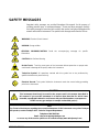
SAFETY MESSAGES
Important safety messages are provided throughout this manual for the purpose of
avoiding personal injury or instrument damage. Please read these messages carefully.
Each safety message is associated with a safety alert symbol, and placed throughout this
manual and inside the instrument. The symbols with messages are defined as follows:
WARNING: Electrical Shock Hazard
HAZARD: Strong oxidizer
GENERAL WARNING/CAUTION: Read the accompanying message for specific
information.
CAUTION: Hot Surface Warning
Do Not Touch: Touching some parts of the instrument without protection or proper tools
could result in damage to the part(s) and/or the instrument.
Technician Symbol: All operations marked with this symbol are to be performed by
qualified maintenance personnel only.
Electrical Ground: This symbol inside the instrument marks the central safety grounding
point for the instrument.
CAUTION
This instrument should only be used for the purpose and in the manner described in
this manual. If you use this instrument in a manner other than that for which it was
intended, unpredictable behavior could ensue with possible hazardous consequences
.
NEVER use any gas analyzer to sample combustible gas(es)!
Note
For Technical Assistance regarding the use and maintenance of this instrument or any other Teledyne
API product, contact Teledyne API’s Technical Support Department:
Telephone: 800-324-5190
Email: [email protected]
or access any of the service options on our website at http://www.teledyne-api.com/
Page is loading ...

07303C DCN6646 iii
WARRANTY
WARRANTY POLICY (02024F)
Teledyne Advanced Pollution Instrumentation (TAPI), a business unit of Teledyne
Instruments, Inc., provides that:
Prior to shipment, TAPI equipment is thoroughly inspected and tested. Should equipment
failure occur, TAPI assures its customers that prompt service and support will be available.
COVERAGE
After the warranty period and throughout the equipment lifetime, TAPI stands ready to
provide on-site or in-plant service at reasonable rates similar to those of other manufacturers
in the industry. All maintenance and the first level of field troubleshooting are to be
performed by the customer.
NON-TAPI MANUFACTURED EQUIPMENT
Equipment provided but not manufactured by TAPI is warranted and will be repaired to the
extent and according to the current terms and conditions of the respective equipment
manufacturer’s warranty.
PRODUCT RETURN
All units or components returned to Teledyne API should be properly packed for
handling and returned freight prepaid to the nearest designated Service Center. After the
repair, the equipment will be returned, freight prepaid.
The complete Terms and Conditions of Sale can be reviewed at http://www.teledyne-
api.com/terms_and_conditions.asp
CAUTION – Avoid Warranty Invalidation
Failure to comply with proper anti-Electro-Static Discharge (ESD) handling and packing
instructions and Return Merchandise Authorization (RMA) procedures when returning parts
for repair or calibration may void your warranty. For anti-ESD handling and packing
instructions please refer to “Packing Components for Return to Teledyne API’s Customer
Service” in the Primer on Electro-Static Discharge section of this manual, and for RMA
procedures please refer to our Website at http://www.teledyne-api.com under Customer
Support > Return Authorization.

Model 200EU-NOy Option Manual Addendum
iv 07303C DCN6646
This page intentionally left blank.

Model 200EU-NOy Option Manual Addendum
07303C DCN6646 v
TABLE OF CONTENTS
1.0 INTRODUCTION......................................................................................................7
2.0 SPECIFICATIONS ...................................................................................................9
2.1 Specifications ........................................................................................................................9
3.0 GETTING STARTED..............................................................................................11
3.1 Unpacking and Inspection..................................................................................................11
3.2 Electrical and Pneumatic Connections.............................................................................12
3.3 Initial Operation ...................................................................................................................15
4.0 THE T200U-NOY EXTERNAL CONVERTER........................................................17
4.1 Principle of Operation.........................................................................................................17
5.0 CALIBRATION AND ZERO/SPAN (OPTION) CHECKS.......................................19
5.1 Calibration or Cal Check Procedure..................................................................................20
6.0 MAINTENANCE.....................................................................................................23
6.1 Maintenance Schedule........................................................................................................23
6.2 Replacing the Sample Particulate Filters..........................................................................24
6.3 Checking Analyzer Flow Rate ............................................................................................26
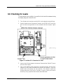
6.4 Replacing the Converter.....................................................................................................26
6.6 Checking for Leaks .............................................................................................................29
7.0 TROUBLESHOOTING, ADJUSTMENTS...........................................................31
7.1 Operation Verification – Diagnostic Techniques.............................................................31
7.1.1 Pneumatic System.............................................................................................................31
7.1.2 Leak Check........................................................................................................................31
7.1.3 501Y Bypass Pump Diagnostic Procedures......................................................................32
7.1.4 Electrical Fault Isolation.....................................................................................................32
7.2 Setting the Converter Temperature.........................................................................................32
7.2.1 Temperature Controller Setup ...........................................................................................32
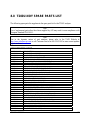
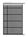
8.0 T200U-NOY SPARE PARTS LIST.....................................................................37

Model 200EU-NOy Option Manual Addendum
vi 07303C DCN6646
List of Figures
Figure 1. Rear Panels: T200U-NOy Analyzer (top) and 501Y (center); Converter (bottom)......................13
Figure 2. Rear Panel Pneumatic Connections............................................................................................14
Figure 3. Replac
ing the Particulate Filter...................................................................................................25
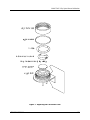
Figure 4. NOy Converter Guts
Assembly Location....................................................................................27
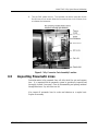
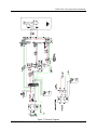
Figure 5. Pneumatics
..................................................................................................................................28
Figure 6. Location of O
3
Generator Air Inlet................................................................................................29
Figure 7. Pneumatics ...................................................................................Error! Bookmark not defined.
Figure 8 Electrical Diagram........................................................................................................................35
List of Tables
Table 1 Specifications for the External Converter and the 501Y Bypass Pump..........................................9
Table 2 Final Test and Calibration Values.................................................................................................15
Table 3 Manual Zero Calibration Procedure..............................................................................................20
Table 4 Enter Expected Span Gas Concentrations Procedure For NO & NOy.........................................20
Table 5 Span Calibration Procedure..........................................................................................................21
Table 6 Preventative Maintenance Calendar.............................................................................................23
Table 7 Temperature Controller Programming Guide ...............................................................................33

07303C DCN6646 7
1.0 INTRODUCTION
The T200U-NOy analyzer consists of an external Converter designed to support a
NOx analyzer by converting multiple, unstable compounds grouped under the
name NOy. The converter is mounted externally at the sample inlet to minimize
flow time between sample in and converter, thereby optimizing measurement
accuracy.
This manual addendum is to be used in conjunction with two additional
documents with operation instructions:
T200 operation manual (part number 06858)
T200U addendum (part number 06861).
It is recommended that you read/familiarize yourself with all sets of instructions
in order to use the analyzer and converter correctly.

Model T200EU-NOy Option Manual Addendum 1.0 Introduction
8 07303C DCN6646
This page intentionally left blank.

07303C DCN6646 9
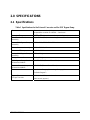
2.0 SPECIFICATIONS
2.1 Specifications
Table 1 Specifications for the External Converter and the 501Y Bypass Pump
Converter Remotely mounted molybdenum external Converter with
temperature controller in a NEMA – 4 enclosure.
Converter Temperature
315
o
C 7
o
C with read-out on front panel of bypass pump chassis.
Tube/Electrical Cable
Assembly
Up to 50 feet (15 m) maximum length
Power, 501Y Bypass Pump
Assembly
120V~ 60 Hz, 230V~ 50 Hz 360 watts
Power, Converter Assembly 120V~ 50/60 Hz, 60 watts
Converter Efficiency >96% for NO2
Weight, 501Y Bypass Pump
Assembly
35 lbs (16 kg)
Weight, Remote Converter 30 lbs (11 kg)
501Y Bypass Pump Chassis
Dimensions HxWxD
9" x17" x23.6" (23cm x 43cm x 61cm)
Remote Converter Assy
Dimensions HxWxD
12"x19"x7" (31cm x 48cm x 18cm)
Environmental Installation Category (Over-voltage Category) II
Pollution Degree 2
Bypass Flow rate
Cal gas Flow rate
800 cc/min 10%, each channel
4000 cc/min (approx.)

Model T200EU-NOy Option Manual Addendum 2.0 Specifications
10 07303C DCN6646
This page intentionally left blank.

07303C DCN6646 11
3.0 GETTING STARTED
The NOy converter has been designed to operate with the T200U low level NOx
analyzer, with some additional modification.The combination is referred to as the
T200U-NOy analyzer.
3.1 Unpacking and Inspection
The T200U- NOy comes in three boxes:
The analyzer with AC power cord
501Y Bypass Pump Chassis (typically referred to as “501Y herein) with AC
power cord
External Converter housed in a stainless steel shelter, and an umbilical cable
assembly (herein referred to as “Converter” or “external Converter”)
External Pump (herein referred to as “external Pump” not to be confused with
the 501Y By
pass Pump)
1. Verify that there is no apparent shipping damage. If damage has
occurred please advise shipper first, then TAPI. (Keep original
container and packaging for shipper’s inspection).
2. Before operating the analyzer, remove the shipping screws as shown in
the T200 Manual.
3. Please check the voltage and frequency label on the rear panel of the
instrument for compatibility with the local power before connecting
the instruments to a power source.
CAUTION!
Avoid personal injury: use two persons each to lift and carry the analyzer and the
Model 501 Pump Pack chassis.

Model T200U-NOy Option Manual Addendum
12 07303C DCN6646
3.2 Electrical and Pneumatic Connections
NOTE
To maintain compliance with EMC standards, it is required that the cable length (at the
rear of the analyzer) be no greater than 3 meters for all I/O connections, which include
Analog In, Analog Out, Status Out, Control In, Ethernet/LAN, USB, RS-232, and RS-485.
1. Mount the Converter (Figure 1, bottom) on a suitable mast.
2. Route the umbilical cable assembly into the shelter of the Converter.
3. Locate the analyzer and 501Y Bypass Pump Chassis in close proximity,
preferably mounting one over the other in a 19” rack.
4. Connect the T200U-NOy analyzer rear panel electrical connectors per the
T200 operation manual.
5. Connect the pneumatic cable fittings from the analyzer rear panel (Figure 1,
top) to the 501Y rear panel (Figure 1, center) and from the 501Y rear panel
to the Converter (Figure 1, bottom).
Refer to Figure 2 for an illustration of the pneumatic connections; refer to the
tags on each tube to match up the correct tube with the appropriate rear panel
fitting.
6. Connect the pneumatic cable fitting from the calibrator to the 501Y rear panel
(
Figure 2).
7. Also connect the EXHAUST port of the analyzer rear panel to the external
Pump.
8. Connect the 7-pin power and signal cable from the external Converter’s
umbilical cable assembly to the CONVERTER POWER connector on the
rear of the 501Y.
9. Connect the analyzer and 501Y AC power cords from their AC power
receptacles to the correct line voltage (refer to power specs on the
respective rear panel label).
WARNING!
Lethal voltages are present inside the chassis.
Do not operate with cover off during normal operation
Before operation, check for correct input voltage and frequency.
Do not operate without proper chassis grounding
Do not defeat the ground wire on power plug
Turn off power before disconnecting electrical subassemblies

Model T200U-NOy Option Manual Addendum
07303C DCN6646 13
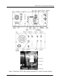
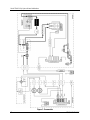
Figure 1. Rear Panels: T200U-NOy Analyzer (top) and 501Y (center); Converter (bottom)

Model T200U-NOy Option Manual Addendum
14 07303C DCN6646
Figure 2. Rear Panel Pneumatic Connections
Note: Pneumatic tubes and rear panel labels include numbers to facilitate matching connections
between instruments.
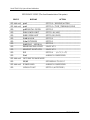
CONNECTIONS: Analyzer to Pump to Converter and Calibrator to Pump
Calibrator Analyzer Pump Chassis Converter
NO IN (1) NO OUT (1)
NOY IN (2) NOY OUT (2)
[cal gas out port] CAL IN (3)
NOY IN (4) NO OUT (4)
NO IN (5) NOY OUT (5)
CAL OUT (6) CAL IN (6)

Model T200U-NOy Option Manual Addendum
07303C DCN6646 15
3.3 Initial Operation
1. After confirming proper supply voltage, turn on the power to the
analyzer and the 501Y bypass pump, and plug in the external Pump. If
you are unfamiliar with the T200U-NOy analyzer, we recommend that
you read the overview in Section 3 of its operation manual before
proceeding.
The front panel displays should immediately light as the
instruments start up.
The 501Y requires about 30 minutes for the external Converter to
come up to operating temperature.
The T200U-NOy requires about 30 minutes for the ozone
generator to start up. During that time the instrument will not
respond to span gas.
After 30 min, the display on the 501Y front panel should read
315
o
C, indicating that the external Converter is at operating
temperature.
Follow the instructions in the T200 Manual and the T200U
Addendum to confirm proper operation of the analyzer.
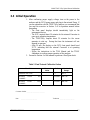
2. Proceed to Section 4 of this manual to perform a Zero/Span check.
Table 2 Final Test and Calibration Values
Test Values Observed
Value
Units Nominal
Range
CONVERTER TEMP
o
C
315 7
BYPASS FLOW – NO
CHANNEL
CC/MIN
800 80
BYPASS FLOW – NOy
CHANNEL
CC/MIN 800 ± 80
Converter Serial # __________________________
Date _______________________ Technician _____________________

Model T200U-NOy Option Manual Addendum
16 07303C DCN6646
This page intentionally left blank.

07303C DCN6646 17
4.0 THE T200U-NOY EXTERNAL CONVERTER
4.1 Principle of Operation
The T-API Model T200U-NOy is designed to measure the concentration of NO,
NO
2
, and other compounds that are too unstable to be measured when taken in
through the normal ambient air sample inlet system. Please refer to the T200U
manual supplied with this system for a general discussion of the operation of a
NOx analyzer. The suite of compounds known collectively as NOy is composed
of roughly 30 compounds. The NOy measurement is generally done in
conjunction with a standard NOx measurement, with the difference between the
two being the concentration of the unstable compounds, sometimes referred to as
NOz.
The analyzer measures two independent gas streams. One bypasses the external
Converter and measures NO in the sample. The other pulls the sample through
the external Converter and is displayed as NOy
.
Under normal calibration
conditions the NOy measurement
is equivalent to the delivered NOx calibration
gases.
The system is composed of four modules:
The T200U-NOy analyzer, without a Moly converter
A 501Y Bypass Pump containing:
bypass pump
flow control
sample filtration
moly temperature control
pneumatic provisions for calibration
Externally mounted molybdenum converter (external Converter)
External Pump
The T200U-NOy system allows the point of sampling to be located in close
proximity to the Converter. This configuration provides minimal time delay
between the sample inlet and the remotely mounted (~10 meters above ground)
external Converter. Minimizing the transit time between the sample inlet and
Converter enables the conversion of labile components of NOy. The equation for
the conversion is:
315
o
C
3 NO
Y
+ Mo ---> 3 NO + MoO
3

Model T200U-NOy Option Manual Addendum
18 07303C DCN6646
This page intentionally left blank.

07303C DCN6646 19
5.0 CALIBRATION AND CAL CHECKS
Unlike most NOx analyzers, the T200U-NOy does not have a sample inlet port
on its rear panel. The sample inlet is located on the external Converter.
Follow the steps in the T200U manual to:
Enter the expected NO and NOy span gas concentrations in the
analyzer.
Do the zero calibration procedure
Do the span calibration procedure
The analyzer always routes the zero/span gas through the external Converter. In
standard configuration, the calibration gas needs to be input at the CAL IN (3)
port of the 501Y bypass pump. In all cases, the calibration gas delivered must be
under a small amount of pressure (2-5 psig) to overcome the resistance of the
tubing.
NOTE
There must be no venting of the Zero or Span gas to atmosphere prior to the analyzer. The
gases actually vent at the external Converter.
Calibration gas must be provided for both the 501Y bypass system and the
analyzer. Flow requirements are 0.80 LPM for NO bypass, 0.80 LPM for NOy
bypass and 1 LPM for the analyzer. Calibration gas flow must be in sufficient
excess (~4 LPM) to prevent any ambient air from entering the sample inlet of the
external Converter.
The maximum 50 ft length of tubing between the 501Y and the remote Converter
has been proven to generate too much backpressure for some brands of
calibrators. Teledyne calibrators are designed to overcome this potential issue.
We strongly recommend that span calibration be done with NO span gas. Span
checks can be done with one of: NO only, NO
2
only, or a mixture of NO and NO
2
(GPT).
Zero air used for all calibration procedures, including GPT, should have <1 ppt
NO and NO
2
, less than 1 ppt of major interferents such as SO
2
, NH
3
,
hydrocarbons and a dew point of -5
o
C or less. The calibration gasses should be
from a reliable supplier, since the quality of the tank concentration values
ultimately determines the accuracy of the analyzer.
NOTE
The T200U-NOy does NOT have equivalency approval.

Model T200U-NOy Option Manual Addendum
20 07303C DCN6646
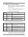
5.1 Calibration or Cal Check Procedure
Calibration of the analyzer can be checked or adjusted using gas introduced
through the CAL IN (3) port on the 501Y rear panel. The calibration gas is
routed to a tee fitting (see CAL IN (6) in Figure 4), near the sam
ple inlet on the
external Converter assembly.
Since the zero gas concentration is defined as 0 ppb, it is not necessary to enter
the expected zero value. Table 3 details the zero calibration procedure.
Table 3 Manual Zero Calibration Procedure
Step
Number
Action Comment
1. Press CAL The analyzer enters the calibrate mode.
2. Wait For Stability
Type STB < 0.1 PPB
Wait for reading to stabilize at zero value.
3. Press ZERO If you change your mind after pressing ZERO, you can still
press EXIT here without zeroing the instrument.
4. Press ENTR Pressing ENTR actually changes the calculation equations.
5. Press EXIT The analyzer returns to sampling. Immediately after
calibration, data is not added to the DAS averages.
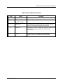
Table 4 Enter Expected Span Gas Concentrations Procedure For NO & NOy
Step Action Comment
1. Press
CAL>CONC>NOy
This menu sequence causes the analyzer to prompt for the
expected NOy concentration.
Enter the NOy span concentration value by pressing the
applicable touchscreen buttons to set the expected value.
2. Press ENTR ENTR stores the expected NOy span value.
3. Press
CAL>CONC>NO
Now enter the expected NO span concentration as in step one.
4. Press ENTR Pressing ENTR stores the NO span value and returns the
prompt to the CONC menu.
5.
Press EXIT Returns instrument to SAMPLE mode.
If desired, compensation for converter efficiency (CE) can be included in the
NOy concentration calculation. Prior to calibration, the converter efficiency
should either be set to 1.0 or determined per the procedure in the T200 manual.
Page is loading ...
Page is loading ...
Page is loading ...
Page is loading ...
Page is loading ...
Page is loading ...
Page is loading ...
Page is loading ...
Page is loading ...
Page is loading ...
Page is loading ...
Page is loading ...
Page is loading ...
Page is loading ...
Page is loading ...
Page is loading ...
Page is loading ...
Page is loading ...
Page is loading ...
Page is loading ...
-
 1
1
-
 2
2
-
 3
3
-
 4
4
-
 5
5
-
 6
6
-
 7
7
-
 8
8
-
 9
9
-
 10
10
-
 11
11
-
 12
12
-
 13
13
-
 14
14
-
 15
15
-
 16
16
-
 17
17
-
 18
18
-
 19
19
-
 20
20
-
 21
21
-
 22
22
-
 23
23
-
 24
24
-
 25
25
-
 26
26
-
 27
27
-
 28
28
-
 29
29
-
 30
30
-
 31
31
-
 32
32
-
 33
33
-
 34
34
-
 35
35
-
 36
36
-
 37
37
-
 38
38
-
 39
39
-
 40
40
-
 41
41
-
 42
42


Teledyne T200U-NOy User manual
- Category
- Measuring, testing & control
- Type
- User manual
Ask a question and I''ll find the answer in the document
Finding information in a document is now easier with AI
Related papers


Other documents
-
Broan PPH3RF Installation guide
-
Teledyne API T200U/NOy User manual
-
-
-
-
-
-
-
-