Page is loading ...

1
Deluxe Select
Portable Barbecue
21 Series
42,000 BTU
REVA 012605 No. L-C2-15805
Robert H. Peterson Co. • 14724 East Proctor Avenue • City of Industry, CA 91746
WARNING: Improper use, adjustment,
alteration, service or maintenance can result in a
fire or explosion causing property damage, injury
or loss of life. This is a safe appliance when the
instructions in this manual are followed exactly.
Failure to follow installation and operating
instructions in this manual may void the warranty
on this appliance.
CONTENTS
Parts List (Exploded view) Page 2
Planning for Installation Page 3
Gas supply requirements Page 3
Safe Use & Maintenance of Propane cylinders Page 3-4
Checking and Adjusting the Barbecue Page 4- 6
Safety & Maintenance Page 6
Use & Care Page 7
Lighting Instructions Page 8
NOTICE TO INSTALLER:
These instructions must be left with the consumer.
NOTICE TO CONSUMER: Retain for local
inspector’s use and for future reference.
FOR YOUR SAFETY
1. Do not store or use gasoline or other
flammable vapors and liquids in the
vicinity of this or any other appliance.
2. An propane cylinder, not connected for use,
shall not be stored in the vicinity of this
or any other appliance.
FOR YOUR SAFETY
IF YOU SMELL GAS:
1. Shut off the gas to the appliance.
2. Extinguish any open flame.
3. Open Lid.
4. If odor continues, immediately call
your gas supplier or Fire Department.
CODE AND SUPPLY REQUIREMENTS: This
barbecue must be installed in accordance with local
codes and ordinances, or in the absence of local codes,
with the latest
National Fuel Gas Code, ANSI Z223.1,
or
CAN/CGA-B149.1, Natural Gas Installation Code
or
CAN/
CGA-B149.2, Propane Installation Code
..
This appliance and its individual shutoff valves must be
disconnected from the gas supply piping system when
testing the system at pressures in excess of ½ psig.
This appliance must be isolated from the gas supply
piping system by closing its individual manual shutoff
valves during any pressure testing of the gas supply
system at pressures up to and including ½ psig.
Certified to ANSI: Z21.58
Owner’s Manual
Installation and
Operating Instructions
IMPORTANT: READ THESE INSTRUCTIONS CAREFULLY BEFORE BEGINNING INSTALLATION
This manual may not be copied, photocopied, reproduced, translated, or published in any electronic or
machine-readable form in whole or in part without prior written approval of Robert H. Peterson Co.
We reserve the right to amend product
specifications without prior notice.
By amorales at 11:55 am, 2/25/05

2

3
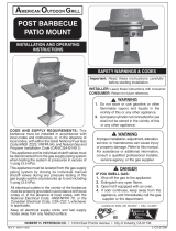
Figure 1 - Ventilation Diagram
PLANNING FOR LOCATION OF THE DELUXE SELECT PORTABLE GAS BARBECUE
WHERE TO LOCATE THE
DELUXE SELECT PORTABLE GAS BARBECUE
Fire Magic gas barbecues are for outdoor use only.
THIS UNIT MUST BE A MINIMUM OF 18” (SIDES &
BACK) FROM ANY COMBUSTIBLE SURFACES
SUCH AS WOOD & STUCCO
Do not use this unit under unprotected flammable
surfaces. Do not use this appliance inside a building,
garage, or any other enclosed area. It must not be
used in or on recreational vehicles or boats.
The front panel (Face) of the unit is removable for
servicing.
INSURING PROPER COMBUSTION AIR AND COOLING
AIR FLOW
You must maintain proper air flow for the barbecue to
perform as it was designed (Figure 1). If airflow is blocked,
overheating and poor combustion will result. Make sure
not to block the 1" front air inlet along the bottom of the
face or more than 75% of the cooking grid surface with
pans or griddles.
Note: The 1" front air space allows access to the drip tray.
ELECTRICAL OUTLETS
Electrical outlets in the vicinity of the barbecue, which
might be used for rotisserie motors or other appliances
must be properly grounded.
INSTALLER AND USER NOTE: Keep electrical supply
cords away from all heated surfaces.
EXHAUST REMOVAL
If installed under a patio roof, the cooking grid area
should be fully covered by a chimney and exhaust hood.
An exhaust fan with a rating of 1000 CFM or more is
necessary to efficiently remove smoke and other cooking
by-products from the covered area. Installation in fully-
enclosed patio areas is not recommended.
GAS SUPPLY PLUMBING REQUIREMENTS
For natural gas or a household propane system. Rigid 1/2" or 3/4” black steel pipe, or local code approved pipe is
required to conduct the gas supply to the unit. An outdoor approved flexible connector can be used to connect your
household gas supply to the barbecue.
Do not use a rubber hose within the enclosure for the barbecue unit. Apply only joint compounds that are
resistant to all gasses on all male pipe fittings. Make sure to tighten every joint securely.
NOTE: If 1/2” pipe is used with natural gas, it should be no longer than 20 feet.
SAFETY NOTE: An external valve (with a removable key) in the gas line is necessary for safety when the barbecue
is not in use. It also provides for convenient maintenance.
Only one propane gas cylinder can be located in the barbecue enclosure. Extra or spare cylinders must be
stored outdoors out of reach of children and outside of any building, garage or other enclosed area.
SAFE USE & MAINTENANCE OF PROPANE GAS CYLINDERS
GAS SUPPLY REQUIREMENTS
READ AND FOLLOW ALL WARNINGS PROVIDED WITH YOUR PROPANE GAS CYLINDER.
IMPORTANT FOR YOUR SAFETY
When operating this appliance with a propane gas cylinder these instructions and warnings (on page 4) MUST be observed.
FAILURE TO DO SO MAY RESULT IN A SERIOUS FIRE OR EXPLOSION.

4
1. CHECK BARBECUE FUEL ORIFICE SIZE
Deluxe Select Portable Barbecues are equipped with fuel
orifices for natural gas, unless otherwise indicated. To
use with propane gas, you must install smaller orifices
to avoid hazardous overheating.
The proper orifice size for Natural Gas is #47 (drill size).
The proper orifice size for Propane Gas is #55 (drill size).
SAFE USE & MAINTENANCE OF PROPANE GAS CYLINDERS cont’d.
QUICK COUPLER OPERATION
To connect the regulator/hose assembly to the L.P. gas
cylinder valve fitting: Press the hand nut on the regulator
over the acme thread fitting on the cylinder valve. Turn the
hand nut clockwise to engage the threads and tighten until
snug. The use of pliers or wrench should not be necessary.
To disconnect: Turn the hand nut counterclockwise until
detached. (Figure 2A).
Important: Before using the barbecue and after each time
the cylinder is removed and reattached, check all connections
for leaks. Turn off the barbecue valves and open the main
cylinder valve, then check connections with soapy water.
Repair any leaks before lighting the barbecue.
CAUTION: Always turn the propane cylinder main valve off
after each use and before moving the barbecue and cylinder
or disconnecting the coupling. This valve must remain closed
while the appliance is not in use, even though the gas flow is
stopped by a safety feature when the coupler is disconnected.
Carefully inspect the hose assembly each time before the
gas is turned on. A cracked or frayed hose should be replaced
immediately.
If the appliance is stored indoors, the cylinder must be
disconnected and removed. Cylinders must be stored out
of the reach of children and must not be stored in a building,
garage or any other enclosed area.
FOR YOUR SAFETY
a. DO NOT store a spare propane gas cylinder under
or near this appliance.
b. NEVER fill the cylinder beyond 80 percent full.
c. IF THE INFORMATION IN “A” AND “B” IS NOT
FOLLOWED EXACTLY, A FIRE CAUSING DEATH
OR SERIOUS INJURY MAY OCCUR.
CYLINDER AND CONNECTOR REQUIREMENTS AND
SPECIFICATIONS
a. Propane gas cylinders and valves must be maintained in
good condition and must be replaced if there is visible damage
to either the cylinder or valve.
b. This barbecue, when used with a cylinder, should be
connected to a standard 5 gallon (20lb.) Propane gas cylinder
equipped with an OPD (Overfill Prevention Device). The OPD
has been required on all cylinders sold since October 1,1998
to prevent overfilling.
c. Cylinder dimensions should be approximately 12 inches in
diameter and 18 inches high. Cylinders must be constructed
and marked in accordance with the specifications for Propane
Gas Cylinders of the U.S. Department of Transportation (D.O.T)
or National Standard of Canada,CAN/ CSA-B339, Cylinders,
Spheres and Tubes for Transportation of Dangerous Goods.
d. The cylinder must include a collar to protect the cylinder
valve and the cylinder supply system must be arranged for
vapor withdrawal.
e. Pressure regulator and hose assembly (Figure 2A) supplied
with this outdoor cooking gas appliance must be used. Original
and replacement pressure regulator and hose assemblies must
be those specified by Robert H. Peterson Co. for connection
with a cylinder connecting device identified as Type I by the
Harmonized Standard ANSI Z 21.58 and CGA 1.6-M95-1995
with Addenda ANSI Z 21.58a -1998 and CGA 1.6a - M98.
f. Propane gas cylinder valve must be equipped with a cylinder
connection coupling device, described as Type I in
Harmonized ANSI standard defined in paragraph e. above.
This is described as an Acme Thread Quick Coupler.
g. Your propane gas cylinder may be equipped with a Type II
Quick Disconnect (plug-in) Coupler (Figure 2B). An approved
regulator /hose assembly for this type of coupling is available
through your dealer from R.H. Peterson Co.
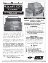
HANDWHEEL
BRASS COUPLING
PRESSURE
RELIEF VALVE
TYPE II
CYLINDER VALVE
(QUICK DISCONNECT
COUPLER)
CYLINDER
LIQUID LEVEL
INDICATOR
(OPTIONAL)
REGULATOR
HOSE
NIPPLE
U
L
VENT
Figure 2B Type II Quick Disconnect Coupler
REGULATOR
HOSE
VENT
HAND NUT
WITH
ACME THREAD
HANDWHEEL
BRASS ACME
THREAD FITTING
PRESSURE
RELIEF VALVE
QCC TYPE I
CYLINDER VALVE
(ACME THREAD
QUICK COUPLER
)
CYLINDER
LIQUID LEVEL
INDICATOR
(OPTIONAL)
U
L
Figure 2A Type I Acme Thread Quick Coupler
2. IF YOU ARE NOT SURE YOU HAVE THE CORRECT
BARBECUE BURNER ORIFICE SIZE
a. Remove the air shutter access panel, located under
the right side rigid shelf (see Parts List)
b. Release with a screwdriver and remove one of the
stainless steel hold down clips which are holding down
the back end of each burner.
c. Check the orifice size by lifting the burner up off of
the back side of the unit and pulling it away from the
orifice. The orifice can be easily removed with a 3/8” hex
screwdriver. The drill size is stamped on the face of each
orifice. Be sure not to lose the air shutter or air shutter
spring which will become detached when the burner is
removed.
d. Change all orifices if necessary, following instructions
provided with the replacement orifices (furnished with
all Fire Magic Gas Barbecues).
e. After checking orifice drill size, install the air shutter
spring and the air shutter over the orifice holder fitting,
between the burner and the heat shield, in the order and
position shown in (Figure 3).
CHECKING AND ADJUSTING YOUR BARBECUE

5
BURNER MANIFOLD
BURNER
ORIFICE
SPRING
AIR SHUTTER
BURNER NECK
HOLD DOWN
CLIP
INNER LINER
f. Carefully place the burners back so that the brass orifice
and burner manifold fittings project deeply into the burners.
Figure 4 - Flavor Grid Diagram
INSTALL THE FLAVOR GRID
Place the flavor grids directly on the burners. Center the
grid over the burners with the open side up. This allows heat
from burners to be evenly distributed through cooking area.
The flavor grid heats and cools quickly, making your Fire
Magic Barbecue very responsive to the changes you
specify in grill temperature.
The flavor grid is made of stainless steel or coated with
high temperature porcelain. Either finish is rust resistant
and may be cleaned with standard oven cleaners.
IMPORTANT: This appliance will not light and will
not heat evenly or cook properly unless the air
shutters are adjusted following installation
(Reference "Air Shutter Adjustment", below).
Burner air shutters are easily accessed by removing the
panel (using a hex driver), located under the right rigid
shelf (see Figure 5). The air shutters are located at the
front of the burners behind the panel (see Parts List).
Figure 3 - Burner Orifice Diagram
CHECKING AND ADJUSTING YOUR BARBECUE (CONTINUED)
The air shutter has a small dimple (see Figure 6A), which
allows it to lock into notches in the burner face. This
prevents the air shutter from moving. Close the air
shutters by turning the tabs to a vertical position. (Figure
6B). Light your barbecue in accordance with the ‘Lighting
Instructions” (page 8) and burn for 2 minutes with the
valves on ‘HIGH’ and the oven open.
AIR SHUTTER ADJUSTMENT
After burning for 1 to 2 minutes, open the air shutters
until the flames lift off, or appear not to be touching the
burners (Figure 6A). Then begin closing the air shutters
until the flames appear to burn while touching the burner
ports (Figure 6B). You may then see short yellow tips on
the flames. If flames are a lazy yellow, open the air
shutters until the flame is blue with yellow tipping.
The barbecue regulator, located behind the front panel (Face),
must be set for the type of gas used to fuel the barbecue. To
check the regulator setting remove the cap in the center of
the regulator (Figure 7A). Holding the cap vertical (see Figure
7B), the letters at bottom of the plastic stalk should indicate
the gas type that the reguator is currently set up for. If regulator
is not set for your gas type, remove stalk from cap, invert
and replace into center of cap. Replace cap on regulator,
screwing down until snug.
Figure 7A
Figure 7B
READ GAS
TYPE HERE
BARBECUE REGULATOR.
NOTE THE CAP ON TOP
CHECKING/CONVERTING THE BARBECUE REGULATOR.
WARNING: THIS APPLIANCE REGULATOR IS RATED FOR 1/2 PSI MAXIMUM. IF YOUR GAS SUPPLY IS GREATER THAN 1/2
PSI AN ADDITIONAL REGULATOR MUST BE INSTALLED BEFORE THE BARBECUE.
SEE PAGE 6 ("GAS SUPPLY REQUIREMENTS) FOR PROPER GAS SUPPLY PRESSURE.
PARTIALLY
OPEN
FIGURE 6A
CLOSED
FIGURE 6B
Figure 6A & 6B - Air Shutter Adjustment Diagram
FLAME ON PORTS
FLAME OFF PORTS
TAB
(TURN TABS)
DIMPLE
NOTCH
VIEW OF RIGHT RIGID SHELF
WITH ACCESS PANEL BELOW
Figure 5
OFF
HI
LIGHT
L
O
W
OFF
HI
LIGHT
L
O
W

6
BARBECUE SAFETY INFORMATION & MAINTENANCE
Each time you use your barbecue, make sure that:
1. The area around the barbecue is clear of flammable substances such
as gasoline, yard debris, wood, etc.
2. There is no blockage of the air flow through the vent space located
below the face of the unit.
3. When using propane gas:
a. The special ventilation openings in the enclosure are kept free
and clear of debris.
b. If connected to a propane cylinder, the rubber hose attached to the
regulator is carefully inspected before each use.
c. The propane cylinder, regulator and rubber hose are installed in a
location not subject to heating above 125° F (51° C).
Figure 6
CHECKING AND ADJUSTING YOUR BARBECUE (CONTINUED)
REATTACHING THE FACE & IGNITOR WIRES
Pull the drip tray out far enough to support the face in the
vertical position. Lean the face forward and plug the ignitor
wires into the spark generator.
The large knobs on the face of the barbecue control the valves
and adjust flame height. The first position is ‘HIGH’, the second
‘MEDIUM’ and final ‘LOW’. Flame height can be set anywhere
between ‘HIGh’, ‘MEDIUM’ and ‘LOW’ settings for all cooking
requirements and methods.
Height of flame with the
valve in low position
may be
regulated by means of a small adjusting screw in center of
valve stem. This screw is accessible by removing the plastic
valve knob which pulls straight off the valve stem.
RIGID SHELF
Your barbecue comes with 2 rigid shelves, that must be
attached. These can be attached using the four support
screws provided.
Line up the four (4)
mounting holes
inside the shelf
with the holes in
the side of the
barbecue (Figure
8), and insert the
screws.Tighten
until snug.
Detaching is a
reverse process
of above.
AIR SHUTTER
ACCESS PANEL
SHELF SUPPORT
SCREWS
VIEW FROM UNDER RIGHT SHELF
Figure 8
REPLACING THE SPARK GENERATOR BATTERY
1. Remove the ignitor cover by turning the cover
counterclockwise and lifting it away.
2. The battery is now accessible for removal and replacement.
Make sure that the battery spring is re-installed with
the new battery, and the battery is negative (-) end up.
3. Replace cover by turning it clockwise until it locks into
place
RIGHT!
WRONG!
NOTE: DO NOT AT-
TEMPT TO PULL ON
THE RUBBER CAP.
*NOTE: IF YOU HAVE ACCIDENTLY REMOVED THE
RUBBER CAP, FOLLOWING INSTRUCTIONS BELOW
TO REPLACE IT.
1. Pull the rubber cap and the inner plastic sleeve apart.
3. Turn the cap over and slide the
inner plastic sleeve into the cap.
2. Carefully insert rubber cap
into the ignitor cover so it sits
behind inner lip.
REATTACHING THE FACE & IGNITOR WIRES
Pull the drip tray out far enough to support the face in the vertical position. Lean the face
forward and plug the 2 wires into the terminals on the spark senerator (Figure 9). The wires
can be plugged into either terminal.
IMPORTANT: Test the electrodes for spark before securing the face to the frame (see above
for battery replacement). Place the face on the frame so the front lip of the face covers the
lip on the frame.
Figure 9 - Spark
Generator
4. The burner flames burn evenly along both sides of each burner with a
steady flame (mostly blue with yellow tipping). See “Air Shutter Adjustment”
on page 5. If burner flames are not normal, check orifice and burner for
insects or insect nests (see page 5 and 6, ”Checking Burner Fuel Orifice
Size”, for burner removal and replacement).
5. The drip collector hole is clear and unobstructed. Excessive grease
deposits can result in a grease fire.
6. The in-line gas valve or gas cylinder valve is always shut off when the
barbecue is not in use.

7
Figure 10 - Always rub with the grain
USE AND CARE OF YOUR FIRE MAGIC BARBECUE
CARE OF STAINLESS STEEL COMPONENTS
Your barbecue has a stainless steel oven and front panel, the
following care instructions will keep your unit looking and
working like new. Stainless steel components are constructed
of the finest prime grade type 304 stainless steel. Meticulous
attention has been given to maintain the attractive finish
throughout the manufacturing process. Like stainless steel
used in commercial kitchens, your barbecue requires regular
cleaning and occasional buffing to maintain its bright, clean
appearance. Deposits of dirt and grease can be removed
easily with Fire Magic Foaming Barbecue and Grill Cleaner.
Deposits should be removed before they are allowed to bake
onto the finish. To remove more stubborn deposits, use a
scouring pad recommended for stainless steel. Be sure to
always rub in the direction of the polishing lines (Figure 10).
Oven cleaner may be used, according to manufacture's
instructions, to remove cooked-on food deposits. Special
cleaning agents and polishing pads recommended for stainless
steel are available at your local barbecue dealer, hardware
store or supermarket.
CAUTION: Never
use ordinary steel
wool or steel
brushes on
stainless steel.
Tiny particles left
behind may rust
and stain finish.
Abrasive pads
recommended for
restoring grain in
stainless steel will,
over a period of time, scratch or dull surface of glass or
porcelain-coated products.
BURNER MAINTENANCE
Fire Magic Deluxe Select Portable Burners are constructed of
heavy-duty cast stainless steel or porcelain coated cast iron
and will withstand many years of outdoor use, if ordinary
precautions are taken. Once or twice a year inspect the
burners and determine if scale is building up excessively.
Burners can be removed and scraped to remove debris or
scale from ports. Spray cast iron with vegetable oil occasionally
to inhibit oxidation. Replace burners immediately if they show
any signs of weak or thin walls. Refer to the top of page 5,
Figure 3 for installing burners.
STAINLESS STEEL COOKING GRIDS
Fire Magic stainless steel cooking grids are finished with a
special matte (satin) finish. This special matte-finish provides
a more stick-resistant cooking surface that makes outdoor
barbecuing easy and enjoyable. Because it is made of type
304 stainless steel, you'll enjoy a lifetime of outdoor cooking.
For best cooking performance, follow the simple steps of ‘Care
and Maintenance’ after every use. Fire Magic Stainless Steel
Cooking Grids are warranted for as long as you own them.
To maintain your stainless steel cooking grids we recommend
lightly brushing the grids before use with a brass or stainless
steel wire brush. After use, brush again if necessary and spray
a light coat of vegetable oil over the cooking surface.
Discoloration or stubborn food particles can be removed with
a heavy-duty abrasive or stainless steel scouring pad. Grills
can also be washed in an automatic dishwasher or cleaned
with strong cleaning solutions, including oven cleansers. We
do not recommend ordinary steel or wire brushes, which may
leave tiny metal particles on grids which cause discoloration,
but not permanent damage.
PORCELAIN COATED CAST IRON GRIDS
Fire Magic porcelain-finished cast-iron grids are coated with a
special high-temperature porcelain in a matte (satin) finish.
This special matte-finish porcelain coating provides a stick
resistant cooking surface that makes outdoor barbecuing
easy and enjoyable. And, because it resists corrosion, the
finish also increases cooking grid durability to provide years of
cooking enjoyment. For best cooking performance, the wide
side of the grid bars should face up.
A spray coat of vegetable oil and light brushing with a brass
grid brush before and after use is all it takes to maintain
cooking readiness and ensure long life.
PROTECTING PARTS AND FINISH
Barbecue covers will protect the finish and extend the life and
appearance of Fire Magic Barbecues equipped with smoke
ovens. The cover is designed to protect the finish against
scratches, corrosion and oxidation. Each cover has been cut
and sewn by hand to ensure a proper fit on the Deluxe Select.
WIPE WITH GRAIN
DRIP COLLECTION SYSTEM
The drip collector in this Fire Magic Barbecue is part of the unit’s main
frame, and is located below burners.Drip collector has one hole which
allows excess drippings to fall through during cooking while separating
firebox from drip tray.
The drip collector allows you to brush or scrape residue from the barbecue
inner liner into the drip tray. Regular cleaning of your barbecue interior with
oven cleaner or Fire Magic Foaming and Grill Cleaner, following
manufacturer’s instructions, will prevent grease fires.
WARNING: Never cover the
entire
cooking or grill surface with griddles or pans. Overheating will occur and
burners will not perform properly when combustion heat is trapped below the cooking surface.
CAUTION: Never spray water on a hot gas unit as this may damage porcelain or cast iron components.
BARBECUE SAFETY INFORMATION & MAINTENANCE cont.
PREPARING THE BARBECUE FOR COOKING
To extend the life of your Fire Magic Barbecue, follow these steps prior to
cooking:
1. Begin by heating the unit at a normal cooking temperature for several
minutes.
2. Then open the control valves to the ‘HIGH’ setting to burn off residue
remaining from prior use.
3. When the barbecue has heated sufficiently, set heat to the desired
cooking level.
4. When using a smoke oven, closing the cover during the preheat period
will accelerate the preparation process. Do not operate unattended at high
flame as cooking temperatures will quickly be exceeded.

8
LIGHTING INSTRUCTIONS
Follow these instructions each time you light your Fire Magic
Barbecue.
FOR AUTOMATIC LIGHTING:
1. Read these instructions before lighting.
2. Open the lid of the smoke oven.
3. Turn both barbecue gas valves to the ‘OFF’ position.
4. Turn on the gas at the source outside of the barbecue
enclosure.
NOTE: Turn on one valve at a time for either automatic or
manual lighting. Adjacent barbecue burner will cross-ignite.
In some conditions the barbecue may light quicker if both
valves are turned on.
5. Push either gas valve and turn to ‘HIGH’ then immediately
use the spark generator to ignite your burners (see Figure
11). The burner should light.
CAUTION: If the burners do not light, IMMEDIATELY turn
the valve to ‘OFF’ and WAIT 5 MINUTES before repeating
step 5. If the burners still do not light, refer to the
instructions for ‘Manual Lighting’ to the right.
NOTE: Barbecues frequently achieve a better air/gas
mixture and will ignite more quickly if the valve is first
turned beyond ‘HIGH’ to ‘MEDIUM’ or ‘LOW’ for lighting.
Figure 11 - Valve Control Knob
Figure 13 - Manual Lighting
OFF
H
I
L
IG
H
T
LOW
T
O
T
U
R
N
O
F
F
T
O
T
U
R
N
O
N
READ SETTING
HERE
HIGH TO
LIGHT
REMEMBER: FOR SAFE MANUAL LIGHTING, PLACE A
BURNING MATCH OR BUTANE LIGHTER BESIDE THE
BURNER - THEN TURN ON THE GAS (Figure 13).
IF YOU SMELL GAS
1. Shut off gas to the appliance.
2. Extinguish any open flame.
3. Open lid.
4. If the odor continues, immediately call
your gas supplier or fire department.
FOR MANUAL LIGHTING:
CAUTION: Always wait 5 minutes for gas to clear after
any unsuccessful lighting attempt.
1. Follow steps 1 through 4 above.
2. Insert either a burning long-barrel butane lighter, a burning
long-stem match or a burning match held by the match
holder (Figure 12), attached to the drip tray through the
cooking grids to the burners below the flavor grid.
3. While holding the match or lighter flame next to the burner,
depress the appropriate valve knob and turn it
counterclockwise to the ‘HIGH’ position. Adjacent burners
will cross-ignite.
4. If the burner does not light, IMMEDIATELY turn the valve
to ‘OFF’ and WAIT 5 MINUTES before repeating steps 2
through 4 of these instructions.
MELBORP
ESUACELBISSOP
NOITCERROC
eruliaFmetsySnoitingI
.tnemtsujdarettuhsriareporpmI)1
detcennocsideriwnoi
tingI)2
erusserpsagwoL)3
yrettaBdaeD)4
)5egaPees(srettuhsriatsujdA)1
)6egaPees(rotarenegkrapsotniseriwgulp-eR)2
taerusserpgnitarepoehtkcehc.oCsaGevaH)3
eucebrabeht
)6egaPees(yrettabecalpeR)4
taeHtneiciffusnI
tne
mtsujdarettuhsriareporpmI)4
saGlarutaNrofecifiroenaporPgnisU)5
erusserPsaGwoL)6
)5egaPees(srettuhsriatsujdA)4
)4egaPees(secifiroegnahC)5
taerusserpgnitarepoehtkcehc.oCsaGevaH)6
eucebrabeht
gnitaehnevenU
sirbedy
bdekcolbyllaitrapstroprenruB)7
renrubnistcesnirosredipsllamS)8
tnemtsujdarettuhSriAreporpmI)9
stroptuonaelc)4egaPees(srenrubevomeR)7
rof)4egaPees(secifirodnasrenrubtcepsnI)8
wolfkcolbyamtahtsirbedrehtorosbew
redips
)5egaPees(rettuhsriatsujdA)9
ysioNeiressitoRecnalabfotuoeiressitoR)01 ecnalabretnuoceiressitortsuj
dA)01
If you have trouble with your Fire Magic Gas Barbecue, please use this list to identify the problem. By trying one or more of the solutions
to the possible cause you should be able to solve the problem. If this list does not cover your present problem or you have other technical
difficulties with the barbecue, please contact your local Fire Magic dealer or visit our website at
www.rhpeterson.com
PROBLEMS & TROUBLESHOOTING
Figure 12 - Match Holder
/