
TH-42LFP30W
TH-47LFP30W
Model No.
Operating Instructions
FULL HD LCD Display
For more detailed instructions, refer to the Operating
Instructions on the CD-ROM.
h
English
Contents
•
Precautions for Installation .............................2
•
Important Safety Instructions ..........................4
•
FCC STATEMENT ..........................................5
•
Important Safety Notice ..................................6
•
Safety Precautions .........................................7
•
Accessories...................................................10
•
Connections ..................................................12
•
Power On / Off ..............................................14
•
Selecting the input signal ..............................16
•
Basic Controls...............................................17
•
On-Screen Menu Displays ............................19
•
Specifi cations................................................20
•
Panasonic Professional Flat Panel Display
Limited Warranty ...........................................21
•
LIMITED WARRANTY STATEMENT ...........22
•
Customer Service .........................................23
Please read these instructions before operating your set
and retain them for future reference.
T6103565460
1AA6P1P6009--

2
• Do not install by yourself. Please ask a installation professional or your dealer to install.
• This product complies with IP66 dust and water protection standard. Do not change or damage dust or water
resistance of the product.
• Please note the dust and water resistance of this product does not guarantee damage or fault free.
CAUTION
Using with dust or water resistance degraded causes fire, electric shock, or
product damage.
This product complies with international standard IP rating (Ingress Protection) dust ingress protection level 6 and
water ingress protection level 6.
Precautions for handling pressure-adjusting caps
Do not loosen or remove the pressure-adjusting caps (2) for the terminal cover.
This will damage the cabinet airtightness.
Do not block the ventilation such as covering the pressure-adjusting caps.
• The pressure-adjusting caps are used to adjust the air pressure inside of the product.
Special material is used so that they let air pass but not liquid such as water.
Terminal cover
After connecting cable etc. of the device to the terminals, check if the terminal cover is sealed correctly and closed
fi rmly using all the fi xing screws when attaching the terminal cover.
To seal the terminal cover correctly, be aware of the following points:
Check if the fi xing sealant is fi xed in the correct position in the cover. Fixing sealant is an important part to
seal the cable part.
Fixing sealant
Fixing sealant
Terminal cover rear side
Fixing sealant
Stick the cable to the shape of the dent on the terminal strip base tightly.
●
The structure is to keep the airtightness
by tucking the cable pulled out along the
dent on the terminal strip base with both
fixing sealant of the terminal strip base
and terminal cover.
Terminal part on
main unit rear side
Terminal cover
Pressure-adjusting caps
Precautions for Installation

3
Power cable
To keep the waterproof property, do not loosen the part fi xing
the power cable to the rear plate.
Do not force to bend the protruding part of the power cable.
This may cause disconnection.
Protective coating
Cabinet aluminum parts and rear plate are protected from corrosion wth coating. Be careful not to damage
the surface. In case the surface is damaged, corrosion may occur from there.
Installation position
Do not install the product to a place where the product is exposed to direct sunlight.
• If the screen is exposed to direct sunlight, the liquid crystal panel may have adverse effect.
• When direct sunlight is on the screen, black shadow may appear. This will disappear when the temperature
drops.
• To avoid direct sunlight, installing a “canopy” above this product is recommended.
• To install the product long term in a special environment such as near a swimming pool, hot spring, or ocean, or in
a factory uses chemicals or gases, please consult your local Panasonic dealer beforehand.
Installation conditions
To use the product in an environment where outdoor air temperature is lower than 39 °F (4 °C), make sure
to set the “Winter Mode” to “On”. The inside temperature is kept constant and the startup can be performed
smoothly.
Do not exhibit or use this product in a condition where water splashes on to it continuously for long time.
To install on a wall etc.
• Consult your dealer about fi ttings etc. beforehand.
• Choose a permanent position where the total weight of the product and fi ttings can be hold permanently. If the
strength of the position is not suffi cient, a serious accident such as fall may be caused.
• Do not install the product where a person can be hang or lean on, or a passer may collide into. Accident may be
caused.
• Take measures for tipping over and fall with an assumption of a fi tting or installation location failure.
• Installation strength may be degraded due to aging depends on the environment. Ask a installation professional to
inspect or repair regularly.
• When an abnormality or fault such as loose screw is detected, ask an installation professional or your dealer
immediately for repair.
• Panasonic will not be responsible for any damages from an accident such as defect of installation, improper use,
modifi cation, or natural disaster.
Precautions for Installation

4
WARNING: To reduce the risk of electric shock, do not remove cover or back.
No user-serviceable parts inside. Refer servicing to qualifi ed service personnel.
The lightning flash with
arrow-head within a triangle
is in tend ed to tell the user
that parts inside the product
are a risk of electric shock
to per sons.
The exclamation point within
a triangle is intended to
tell the user that important
operating and servicing
instructions are in the papers
with the ap pli ance.
CAUTION
RISK OF ELECTRIC SHOCK
DO NOT OPEN
WARNING : To prevent damage which may result in fi re or shock hazard, do not expose this apparatus to rain
or mois ture.
Do not place containers with water (fl ower vase, cups, cosmetics, etc.) above the set.
(including on shelves above, etc.)
WARNING : 1) To prevent electric shock, do not remove cover. No user serviceable parts inside. Refer servicing to
qualifi ed service personnel.
2) Do not remove the grounding pin on the power plug. This apparatus is equipped with a three pin
grounding-type power plug. This plug will only fi t a grounding-type power outlet. This is a safety fea ture.
If you are unable to insert the plug into the outlet, contact an electrician.
Do not defeat the purpose of the grounding plug.
As an ENERGY STAR
®
Partner, Panasonic has determined that this product meets the
ENERGY STAR
®
guidelines for energy effi ciency.
1) Read these instructions.
2) Keep these instructions.
3) Heed all warnings.
4) Follow all instructions.
5) Do not use this apparatus near water.
6) Clean only with dry cloth.
7) Do not block any ventilation openings. Install in accordance with the manufacturer’s instructions.
8) Do not install near any heat sources such as radiators, heat registers, stoves, or other apparatus (including
amplifi ers) that produce heat.
9) Do not defeat the safety purpose of the polarized or grounding-type plug. A polarized plug has two blades with
one wider than the other. A grounding type plug has two blades and a third grounding prong. The wide blade
or the third prong are provided for your safety. If the provided plug does not fi t into your outlet, consult an
electrician for replacement of the obsolete outlet.
10) Protect the power cord from being walked on or pinched particularly at plugs, convenience receptacles, and
the point where they exit from the apparatus.
11) Only use attachments / accessories specifi ed by the manufacturer.
12) Use only with the cart, stand, tripod, bracket, or table specifi ed by the manufacturer, or sold with
the apparatus. When a cart is used, use caution when moving the cart / apparatus combination
to avoid injury from tip-over.
13) Unplug this apparatus during lightning storms or when unused for long periods of time.
14) Refer all servicing to qualifi ed service personnel. Servicing is required when the apparatus has
been damaged in any way, such as power-supply cord or plug is damaged, liquid has been
spilled or objects have fallen into the apparatus, the apparatus has been exposed to rain or moisture, does not
operate normally, or has been dropped.
15) To prevent electric shock, ensure the grounding pin on the AC cord power plug is securely connected.
Important Safety Instructions
This ENERGY STAR mark is applicable in USA only.

5
This equipment has been tested and found to comply with the limits for a Class B digital device, pursuant to Part
15 of the FCC Rules. These limits are designed to provide reasonable protection against harmful interference
in a residential installation. This equipment generates, uses and can radiate radio frequency energy and, if not
installed and used in accordance with the instructions, may cause harmful interference to radio communications.
However, there is no guarantee that interference will not occur in a particular installation. If this equipment does
cause harmful interference to radio or television reception, which can be determined by turning the equipment
off and on, the user is encouraged to try to correct the interference by one or more of the following measures:
• Reorient or relocate the receiving antenna.
• Increase the separation between the equipment and receiver.
• Connect the equipment into an outlet on a circuit different from that to which the receiver is connected.
• Consult the dealer or an experienced technician for help.
This device complies with Part15 of the FCC Rules. Operation is subject to the following two conditions:(1) This
device may not cause harmful interference, and (2) this device must accept any interference received, including
interference that may cause undesired operation.
FCC CAUTION:
To assure continued compliance, follow the attached installation instructions and use only shielded
interface cables when connecting to computer or peripheral devices. Any changes or modifi cations not
expressly approved by Panasonic Corp. of North America could void the user's authority to operate this
device.
FCC Declaration of Conformity
Model No. TH-42LFP30W, TH-47LFP30W
Responsible Party: Panasonic Corporation of North America
Three Panasonic Way 2F-5, Secaucus, NJ 07094
Contact Source: Panasonic Solutions Company
Panasonic Plasma Concierge 1-800-973-4390
CANADIAN NOTICE:
This Class B digital apparatus complies with Canadian ICES-003.
FCC STATEMENT

6
Important Safety Notice
WARNING
1) No naked fl ame sources, such as lighted candles, should be placed on / above the set.
2) To prevent electric shock, do not remove cover. No user serviceable parts inside. Refer servicing to qualifi ed
service personnel.
3) Do not remove the earthing pin on the power plug. This apparatus is equipped with a three pin earthing-type
power plug. This plug will only fi t an earthing-type power outlet. This is a safety feature. If you are unable to
insert the plug into the outlet, contact an electrician.
Do not defeat the purpose of the earthing plug.
4) To prevent electric shock, ensure the earthing pin on the AC cord power plug is securely connected.
CAUTION
This appliance is intended for use in environments which are relatively free of electromagnetic fi elds.
Using this appliance near sources of strong electromagnetic fi elds or where electrical noise may overlap with the
input signals could cause the picture and sound to wobble or cause interference such as noise to appear.
To avoid the possibility of harm to this appliance, keep it away from sources of strong electromagnetic fi elds.
IMPORTANT: THE MOULDED PLUG IMPORTANT: THE MOULDED PLUG
FOR YOUR SAFETY, PLEASE READ THE FOLLOWING TEXT CAREFULLY.
This display is supplied with a moulded three pin mains plug for your safety and convenience. A 10 amp fuse is
fi tted in this plug. Shall the fuse need to be replaced, please ensure that the replacement fuse has a rating of 10
amps and that it is approved by ASTA or BSI to BS1362.
Check for the ASTA mark
ASA
or the BSI mark on the body of the fuse.
If the plug contains a removable fuse cover, you must ensure that it is refi tted when the fuse is replaced.
If you lose the fuse cover the plug must not be used until a replacement cover is obtained.
A replacement fuse cover can be purchased from your local Panasonic dealer.
Do not cut off the mains plug.
Do not use any other type of mains lead except the one supplied with this display.
The supplied mains lead and moulded plug are designed to be used with this display to avoid
interference and for your safety.
If the socket outlet in your home is not suitable, get it changed by a qualifi ed electrician.
If the plug or mains lead becomes damaged, purchase a replacement from an authorized dealer.
WARNING : — THIS DISPLAY MUST BE EARTHED.
How to replace the fuse.
Open the fuse compartment with a screwdriver and replace the fuse.
Trademark Credits
• VGA is a trademark of International Business Machines Corporation.
• Macintosh is a registered trademark of Apple Inc., USA.
• SVGA, XGA, SXGA and UXGA are registered trademarks of the Video Electronics Standard Association.
Even if no special notation has been made of company or product trademarks, these trademarks have been fully respected.
• HDMI, the HDMI Logo, and High-Defi nition Multimedia Interface are trademarks or registered trademarks of HDMI
Licensing LLC in the United States and other countries.
Note:
Image retention may occur. If you display a still picture for an extended period, the image might remain on the screen.
However, it will disappear after a while.

7
Safety Precautions
Always be sure to ask a qualifi ed technician to carry out set-up.
Small parts can present choking hazard if accidentally swallowed. Keep small parts away from young children. Discard
unneeded small parts and other objects, including packaging materials and plastic bags/sheets to prevent them from
being played with by young children, creating the potential risk of suffocation.
Do not place any objects on top of the Display.
• If any foreign objects get inside the Display, please consult your local Panasonic dealer.
Transport only in upright position!
• Transporting the unit with its display panel facing upright or downward may cause damage to the internal
circuitry.
Releasing heat should not be impeded by covering the surface of this display with items such as newspapers,
table cloths and curtains.
For suffi cient heat release;
Leave a space of 3 15/16” (10 cm) or more at the top, left and right, and 1 31/32” (5 cm) or more at the rear, and
also keep the space between the bottom of the display and the fl oor surface.
• This product has a structure to let the heat out from the cabinet surface.
• Use the product within the operating condition temperature range.
Cautions for Wall Installation
• Wall installation should be performed by an installation professional. Installing the Display incorrectly may lead to
an accident that results in death or serious injury. Furthermore, when installing on a wall, a wall hanging bracket
that conforms to VESA standards (VESA 400 × 400) must be used.
• When installing the Display vertically, turn up the power indicator for the upward direction.
WARNING
Setup

8
Safety Precautions
When using the LCD Display
The Display is designed to operate on 110 - 127 or 220 - 240 V AC, 50/60 Hz.
Attach the terminal cover fi rmly to use.
• Otherwise the dust and water resistance is damaged and may cause fi re, electric shock or product damage.
Do not stick any foreign objects into the Display.
• Do not insert any metal or fl ammable objects into the Display or drop them onto the Display, as doing so can cause
fi re or electric shock.
Do not remove the cover or modify it in any way.
• High voltages which can cause severe electric shocks are present inside the Display. For any inspection, adjustment
and repair work, please contact your local Panasonic dealer.
Ensure that the mains plug is easily accessible.
An apparatus with CLASS I construction shall be connected to a mains socket outlet with a protective earthing connection.
Do not use any power supply cord other than that provided with this unit.
• Doing so may cause fi re or electric shocks.
Securely insert the power supply plug as far as it will go.
• If the plug is not fully inserted, heat may be generated which could cause fi re. If the plug is damaged or the wall
socket is loose, they shall not be used.
Do not handle the power supply plug with wet hands.
• Doing so may cause electric shocks.
Do not do anything that may damage the power cable. When disconnecting the power cable, pull on the plug body, not the cable.
• Do not damage the cable, make any modifi cations to it, place heavy objects on top of it, heat it, place it near any
hot objects, twist it, bend it excessively or pull it. To do so may cause fi re and electric shock. If the power cable is
damaged, have it repaired at your local Panasonic dealer.
If the Display is not going to be used for any prolonged length of time, unplug the power supply plug from
the wall outlet.
To prevent the spread of fi re, keep candles or other open fl ames away from this product at all times.
If problems occur during use
If a problem occurs (such as no picture or no sound), or if smoke or an abnormal odour starts to come out
from the Display, immediately unplug the power supply plug from the wall outlet.
• If you continue to use the Display in this condition, fi re or electric shock could result. After checking that the smoke
has stopped, contact your local Panasonic dealer so that the necessary repairs can be made. Repairing the Display
yourself is extremely dangerous, and shall never be done.
If foreign objects get inside the Display, if the Display is dropped, or if the cabinet becomes damages, disconnect
the power supply plug immediately.
•
A short circuit may occur, which could cause fi re. Contact your local Panasonic dealer for any repairs that need to be made.

9
Safety Precautions
CAUTION
When using the LCD Display
Be sure to disconnect all cables before moving the Display.
• If the Display is moved while some of the cables are still connected, the cables may become damaged, and fi re or
electric shock could result.
Disconnect the power supply plug from the wall socket as a safety precaution before carrying out any
cleaning.
• Electric shocks can result if this is not done.
Clean the power cable regularly to prevent it becoming dusty.
• If dust built up on the power cord plug, the resultant humidity can damage the insulation, which could result in fi re.
Pull the power cord plug out from the wall outlet and wipe the mains lead with a dry cloth.
Do not burn or breakup batteries.
• Batteries must not be exposed to excessive heat such as sunshine, fi re or the like.
Power supply
• Install the product near an electrical outlet so that the plug can be unplugged immediately when an abnormality
occurs.
• For a wall installation, used a power outlet which can be unplugged immediately when an abnormality occurs.
• This product is energized when the power plug is inserted to a socket. To cut off the power completely, the power
plug must be unplugged from the socket.
Cabinet
• Corner part of the metal cabinet is a potential injury hazard.
• To lift the product, hold the handles for the precaution of fall. Injury or damage may be caused.
Cleaning and maintenance
The front of the display panel has been specially treated. Wipe the panel surface gently using only a cleaning
cloth or a soft, lint-free cloth.
• If the surface is particularly dirty, wipe with a soft, lint-free cloth which has been soaked in pure water or water in
which neutral detergent has been diluted 100 times, and then wipe it evenly with a dry cloth of the same type until
the surface is dry.
• Do not scratch or hit the surface of the panel with fi ngernails or other hard objects, otherwise the surface may
become damaged. Furthermore, avoid contact with volatile substances such as insect sprays, solvents and thinner,
otherwise the quality of the surface may be adversely affected.
If the cabinet becomes dirty, wipe it with a soft, dry cloth.
• If the cabinet is particularly dirty, soak the cloth in water to which a small amount of neutral detergent has been
added and then wring the cloth dry. Use this cloth to wipe the cabinet, and then wipe it dry with a dry cloth.
• Do not allow any detergent to come into direct contact with the surface of the Display. If water droplets get inside
the unit, operating problems may result.
• Avoid contact with volatile substances such as insect sprays, solvents and thinner, otherwise the quality of the
cabinet surface may be adversely affected or the coating may peel off. Furthermore, do not leave it for long periods
in contact with articles made from rubber or PVC.

+
-
+
-
Accessories Supply
Accessories
Power supply cord
Batteries for the Remote
Control Transmitter
(R6 (UM3) Size × 2)
Remote Control
Transmitter
N2QAYB000535
Operating Instruction book
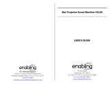
Check that you have the accessories and items shown
Remote Control Batteries
Requires two R6 batteries.
1. Pull and hold the hook, then open
the battery cover.
2. Insert batteries - note correct
polarity ( + and -).
3. Replace the cover.
Helpful Hint:
For frequent remote control users, replace old batteries with Alkaline
batteries for longer life.
Precaution on battery use
Incorrect installation can cause battery leakage and corrosion that will damage the remote control transmitter.
Disposal of batteries should be in an environment-friendly manner.
Observe the following precaution:
1. Batteries shall always be replaced as a pair. Always use new batteries when replacing the old set.
2. Do not combine a used battery with a new one.
3. Do not mix battery types (example: “Zinc Carbon” with “Alkaline”).
4. Do not attempt to charge, short-circuit, disassemble, heat or burn used batteries.
5.
Battery replacement is necessary when remote control acts sporadically or stops operating the Display set.
6. Do not burn or breakup batteries.
Batteries must not be exposed to excessive heat such as sunshine, fi re or the like.
“R6 (UM3)” size
CD-ROM
(Operating
instructions)
Main plug types vary between countries. Make sure to use the power supply cord
with the voltage and shape appropriate to your country and region. (see page 11)
Note:
Remote Control Transmitter is not water
protection type.
10

Accessories
About Power Supply Cord
Main plug types vary between countries. Check the shape of the power plugs to choose the appropriate cable for
you.
Country Name Appropriate AC Cables
Asia
India
Cable B or Cable C
Indonesia
Philippine
Malaysia
Singapore
Cable C
Hong Kong
Middle East
United Arab Emirates
Cable B or Cable C
Iraq
Iran
Oman
Syria
Lebanon
Qatar
Kuwait
Cable C
Saudi Arabia
Africa
Egypt
Cable B or Cable CEthiopia
South Africa
Middle/South America
Uruguay
Cable A or Cable B
Caution:
110-127 V AC: Cable A is adaptable
220-240 V AC: Cable B is adaptable
Ecuador
Colombia
Chili
Panama
Paraguay
Puerto Rico
Venezuela
Peru
Bolivia
Honduras
North America
USA
Cable A (110-127 V AC Compatible)
Canada
Europe
Italy
Cable B
Austria
Netherlands
Greece
Switzerland
Sweden
Spain
Czech
Denmark
Germany
Norway
Hungary
Finland
France
Bulgaria
Belgium
Portugal
Poland
Monaco
Luxembourg
Russia
Kazakhstan
Ukraine
Belarus
UK Cable C
Oceania
Australia
Cable D
New Zealand
Cable A
Plug Type : A
Cable B
Plug Type : SE
S
N
16A 250V~
D
FI
Cable C
Plug Type : BF
NL
Cable D
Plug Type : O
NL
10A 250V~
Insulating sleeve
11

AC cord connection
How to remove terminal cover
Connections
A
Connect the AC cord
Line up and push together connectors A and B
so they are tight and then twist C until A and B
cannot be pulled apart.
Disconnect the AC cord
Unscrew C and pull connector A and B apart.
Note:
When disconnecting the AC cord, be
absolutely sure to disconnect the AC
cord plug at the socket outlet first.
B
C
A
B
C
Notes:
• After connection, check the cable is pulled out along the groove without overlapping, then tighten the all 12 screws
to attach the terminal cover correctly. Otherwise water enters inside and causes fi re, electric shock and product
damage.
• Water-proof washer is used for one screw with marked. To attach the terminal cover, let the water-proof washer
through to attach the marked screw.
• Make sure to read the “Terminal cover” (page 2) section for the correct handling of the terminal cover to use the
product properly.
12
To remove the terminal cover to connect a cable or other item, remove all 12 screws in bottom, middle, then top order
to prevent the terminal cover dropping off. Opening the terminal cover with some screws left on damages the terminal
cover.
Remove the screws (12) to
take out the terminal cover.

Video equipment connection
AV IN
HDMI1, HDMI2
HDMI Input Terminal
COMPONENT/RGB IN
Component/RGB
Video Input Terminal
DVI-D IN
DVI-D Input Terminal
SERIAL
Control the Display by
connecting to PC
EXT SP
Speaker output terminal
PC IN
PC Input Terminal
AV IN
VIDEO
Composite Video Input
Terminal
While pressing
the lever, insert
the core wire.
Return the lever.
Red
Black
Red
Black
Remove the terminal
cover
13
Connections

Power Indicator
Remote Control
Sensor
Power switch
14
Power On / Off
Press the button on the remote control to turn the Display off.
Power Indicator: Red (standby)
Press the button on the remote control to turn the Display on.
Power Indicator: Green
Turn the power to the Display off by pressing the switch on the unit, when
the Display is on or in standby mode.
Note:
During operation of the power management function, the power indicator turns
orange in the power off state.
Connecting the plug to the Wall Outlet
Notes:
• Main plug types vary between countries. The power
plug shown at right may, therefore, not be the type
fi tted to your set. (see page 11)
• When disconnecting the AC cord, be absolutely
sure to disconnect the AC cord plug at the socket
outlet fi rst.
Press the Power switch on the Display to turn the
set on: Power-On.
Power Indicator: Green
Connecting the AC cord plug to the Display. (see page 12)

Italiano
Español
ENGLISH (US)
English (UK)
Deutsch
Français
OSD Language
PRESENT TIME Setup
PRESENT TIME MON 99 : 99
Set
PRESENT TIME
99 : 99
DAY
MON
PRESENT TIME Setup
PRESENT TIME MON 99 : 99
Set
PRESENT TIME
10 : 00
DAY
TUE
Power ON warning message
The following message may be displayed when turning the unit power ON:
No activity power off Precautions
’No activity power off’ is enabled.
If “No activity power off” in Setup menu is set to “Enable”, a warning message is displayed every time
the power is turned ON.
This message display can be set with the following menu: Options menu
Power On Message
15
Power On / Off
When fi rst switching on the unit
Following screen will be displayed when the unit is turned on for the fi rst time.
Select the items with the remote control. Unit buttons are invalid.
OSD Language
PRESENT TIME Setup
1
Select the language.
2
Set.
1
Select “DAY” or “PRESENT TIME”.
2
Setup “DAY” or “PRESENT TIME”.
Notes:
• Once the items are set, the screens won't be displayed when switching on the unit next time.
• After the setting, the items can be changed in the following menus.
OSD Language
PRESENT TIME Setup
No activity power off
1
Select “Set”.
2
Set.
Display will be turned off
when there is no activity for 4 hours.
DisableEnable
No activity power off
Are you sure
you want to enable ’No activity power off’ ?
NoYes
No activity power off
1
To enable No activity power off, select “Enable”.
2
Set.
1
“Select “Yes” or “No”.
2
Set.
If selecting “Enable”, a
confi rmation window appears.
No activity power off

16
Selecting the input signal
Notes:
• Selecting is also possible by pressing the INPUT button on the
unit.
• Select to match the signals from the source connected to the
component/RGB input terminals.
Press to select the input signal to be played back from the equipment which has
been connected to the Display.
Input signals will change as follows:
PC: PC input terminal in PC IN.
DVI: DVI input terminal in DVI-D IN.
HDMI1: HDMI input terminal in AV IN (HDMI1).
HDMI2: HDMI input terminal in AV IN (HDMI2).
VIDEO: Video input terminal in AV IN (VIDEO/S-VIDEO).
Component*: Component or RGB input terminal in COMPONENT/RGB IN.
* “Component” may be displayed as “RGB” depending on the setting of
“Component/RGB-in select”.
PC HDMI1 HDMI2 Component*VIDEODVI

17
Basic Controls
MENU Screen ON / OFF
Each time the MENU button is pressed, the menu screen
will switch. (see page 19)
Volume Adjustment
Volume Up “+” Down “–”
When the menu screen is displayed:
“+” : press to move the cursor up
“–” :
press to move the cursor down
(see page 19)
Remote control
sensor
Main Power On / Off Switch
Brightness Sensor
Detects the brightness in the viewing
environment.
Main Unit
Power Indicator
The Power Indicator will light.
• Power-OFF .... Indicator not illuminated (The unit will still
consume some power as long as the power
cord is still inserted into the wall outlet.)
• Standby ........ Red
• Power-ON ...... Green
• Power management (DPMS)
.......................Orange (PC IN or DVI-D IN signal)
When this function is set to On, it operates
under the following conditions to turn the
power on or off automatically.
When no pictures are detected for 30 or so
seconds during input from PC IN or DVI-D
IN terminal:
→ Power is turned off (standby); the power
indicator lights up orange.
When pictures are subsequently detected:
→ Power is turned on; the power indicator
lights up green.
• No signal power off
.......................Red
Equipment power supply is turned Off when
there is no signal.
When this is set to “Enable”, the power
supply of the unit goes Off 10 minutes after
the input signals stop.
• No activity power off
.......................Red
When this function is set to “Enable”, the
power is turned off (standby) automatically
when there is no operation of the Display
for 4 hours.
Starting from 3 minutes before the turn off,
the remaining time will be displayed.
Enter / Aspect button
(see page 19)
INPUT button
(INPUT signal selection)
(see page 16)
Normal Viewing Picture
Sound Pos. /Size Setup
No activity power off
3min
Press any key to abort.

Off timer
90min
1
2
3
4
10:00
PC
4:3
18
Basic Controls
Remote Control Transmitter
Standby (ON / OFF) button
The Display must fi rst be plugged into
the wall outlet and turned on at the
power switch (see page 14).
Press this button to turn the Display On,
from Standby mode. Press it again to
turn the Display Off to Standby mode.
ACTION button
Press to make selections.
ASPECT button
Press to adjust the aspect.
POS. /SIZE button
PICTURE button
Sound mute On / Off
Press this button to mute the
sound.
Press again to reactivate sound.
Sound is also reactivated when
power is turned off or volume level
is changed.
N button
POSITION buttons
INPUT button
Press to select Input signal
sequentially. (see page 16)
Digital Zoom
AUTO SETUP button
Automatically adjusts the position/
size of the screen.
SET UP button
SOUND button
Volume Adjustment
Press the Volume Up “+” or Down “–”
button to increase or decrease the
sound volume level.
R button (see page 19)
Press the R button to return to
previous menu screen.
OFF TIMER button
The Display can be preset to switch to stand-by
after a fi xed period. The setting changes to 30
minutes, 60 minutes, 90 minutes and 0 minutes
(off timer cancelled) each time the button is
pressed.
30 min 60 min
0 min
90 min
When three minutes remain, “Off timer 3 min”
will fl ash.
The off timer is cancelled if a power interruption
occurs.
RECALL button
Press the “RECALL” button to display
the current system status.
1
Input label
2
Aspect mode
3
Off timer
The off timer indicator is
displayed only when the off
timer has been set.
4
Clock display

1/2
Signal
Input label
Wobbling
Setup
Power management
On
Off
Standby save
On
ECO
Off
OSD Language English
(
UK
)
Component/RGB-in select
RGB
Screensaver
Enable
No activity power off
Enable
No signal power off
2/2Setup
MULTI DISPLAY Setup
Set up TIMER
PRESENT TIME Setup
Menu Display Duration
15 S
Menu Transparency
20
0
Normal
Normalise
Auto Setup
Pos. /Size
V-Pos
0
H-Pos
V-Size
Clock Phase
H-Size
1:1 Pixel Mode
Dot Clock
0
0
0
0
Off
19
On-Screen Menu Displays
Remote Control Unit
1
Display the menu screen.
Press to select.
(Example: Picture menu)
Press several times.
Each time the MENU button is pressed, the
menu screen will switch.
Normal Viewing Picture
Sound Pos. /Size Setup
2
Select the item.
100
70
50
50
50
Picture
Normal
Normalise
Normal
Brightness
Picture Mode
Colour
Contrast
Backlight
Tint
Advanced settings
White balance
Normal
Sharpness
50
(Example: Picture menu)
Select.
Select.
Press.
3
Set.
Adjust.
Adjust.
Press.
4
Exit the menu.
Press.
Press to return to the
previous menu.
Press several times.
100
70
50
50
50
Picture
Normal
Normalise
Normal
Brightness
Picture Mode
Colour
Contrast
Backlight
Tint
Advanced settings
White balance
Normal
Sharpness
50
0
0
0
Sound
Normal
Normalise
Normal
Off
Treble
Sound Mode
Balance
Bass
Surround
see page 26 on the
CD-ROM
Picture menu Setup menu Pos./Size menu Sound menu
see page 22, 23 on the
CD-ROM
see page 27-40 on the
CD-ROM
see page 24, 25 on the
CD-ROM

20
Specifi cations
Notes:
• Design and specifi cations are subject to change without notice. Mass and dimensions shown are approximate.
• This equipment complies with the EMC standards listed below.
EN55022, EN55024, EN61000-3-2, EN61000-3-3.
TH-42LFP30W TH-47LFP30W
For USA, Canada
and Mexico
For Europe and Asia For USA, Canada
and Mexico
For Europe and Asia
Power Source 110 - 127 V AC,
50/60 Hz
220 - 240 V AC,
50/60 Hz
110 - 127 V AC,
50/60 Hz
220 - 240 V AC,
50/60 Hz
Power Consumption
Power on 250 W 240 W 300 W 290 W
Stand-by condition
(Winter Mode: Off)
Save off 0.2 W,
Save on 0.1 W
Save off 0.3 W,
Save on 0.2 W
Save off 0.2 W,
Save on 0.1 W
Save off 0.3 W,
Save on 0.2 W
Stand-by condition
(Winter Mode: On)
Backlight Off 40 W
Backlight On 80 W
Backlight Off 40 W
Backlight On 80 W
Backlight Off 40 W
Backlight On 100 W
Backlight Off 40 W
Backlight On 100 W
Power off condition 0.1 W 0.2 W 0.1 W 0.2 W
LCD Display panel 42-inch IPS panel, 16:9 aspect ratio 47-inch IPS panel, 16:9 aspect ratio
Screen size 36.6” (W) × 20.5” (H) × 42.0” (diagonal) /
930 mm (W) × 523 mm (H) × 1,067 mm
(diagonal)
40.9” (W) × 23.0” (H) × 46.9” (diagonal) /
1,039 mm (W) × 584 mm (H) × 1,192 mm
(diagonal)
(No.of pixels) 2,073,600 (1,920 (W) × 1,080 (H))
[5,760 × 1,080 dots]
2,073,600 (1,920 (W) × 1,080 (H))
[5,760 × 1,080 dots]
Operating condition
Temperature 32 °F - 104 °F / 0 °C - 40 °C (during Winter Mode: -4 °F - 104 °F / -20 °C - 40 °C)
Applicable signals
Colour System NTSC, PAL, PAL60, SECAM, NTSC 4.43, PAL M, PAL N
Scanning format 525 (480) / 60i · 60p, 625 (575) / 50i · 50p, 750 (720) / 60p · 50p, 1125 (1080) / 60i · 60p · 50i ·
50p · 24p · 25p · 30p · 24sF
PC signals VGA, SVGA, XGA, SXGA
UXGA ···· (compressed)
Horizontal scanning frequency 30 - 110 kHz
Vertical scanning frequency 48 - 120 Hz
Connection terminals
AV IN VIDEO
AUDIO L-R
BNC
RCA Pin jack × 2
1.0 Vp-p (75 Ω)
0.5 Vrms
HDMI 1/2 TYPE A Connector
COMPONENT/RGB IN
G/Y
B/P
B/CB
R/PR/CR
AUDIO L-R
BNC
BNC
BNC
RCA Pin jack × 2
with sync 1.0 Vp-p (75 Ω)
0.7 Vp-p (75 Ω)
0.7 Vp-p (75 Ω)
0.5 Vrms
DVI-D IN
AUDIO
DVI-D 24 Pin
Content Protection
Stereo mini jack (M3) × 1
Compliance with DVI Revision 1.0
Compatible with HDCP 1.1
0.5 Vrms, Shared with PC IN
PC IN
AUDIO
High-Density Mini D-sub 15 Pin
Stereo mini jack (M3) × 1
G with sync 1.0 Vp-p (75 Ω)
G without sync 0.7 Vp-p (75 Ω)
B: 0.7 Vp-p (75 Ω)
R: 0.7 Vp-p (75 Ω)
HD/VD: 1.0 - 5.0 Vp-p (high impedance)
0.5 Vrms, Shared with DVI-D IN
SERIAL External Control Terminal
D-sub 9 Pin RS-232C compatible
EXT SP 8 Ω, 10 W [5 W + 5 W] (10 % THD)
Dimensions (W × H × D) 41.3” × 25.3” × 6.3” /
1,049 mm × 642 mm × 158 mm
45.8” × 27.8” × 6.3” /
1,162 mm × 706 mm × 158 mm
Mass (weight) approx. 83.8 lbs / 38.0 kg approx. 99.2 lbs / 45.0 kg
Page is loading ...
Page is loading ...
Page is loading ...
Page is loading ...
-
 1
1
-
 2
2
-
 3
3
-
 4
4
-
 5
5
-
 6
6
-
 7
7
-
 8
8
-
 9
9
-
 10
10
-
 11
11
-
 12
12
-
 13
13
-
 14
14
-
 15
15
-
 16
16
-
 17
17
-
 18
18
-
 19
19
-
 20
20
-
 21
21
-
 22
22
-
 23
23
-
 24
24


Panasonic TH47LFP30W Quick start guide
- Type
- Quick start guide
- This manual is also suitable for
Ask a question and I''ll find the answer in the document
Finding information in a document is now easier with AI
Related papers
-
Panasonic TH42LF25ER Quick start guide
-
Panasonic TH42LF30ER Quick start guide
-
Panasonic TH-47LFP30W Owner's manual
-
-
-
Panasonic TH-65BQ1 User manual
-
-
-
Panasonic TH65PF9BK Operating instructions
-
Other documents
-
Sharp PNZB01 User manual
-
Gemmy AppLights 39109 User manual
-
 Worldwide Home Products H199229 User manual
-
 RF-Link Technology DAV-2450 User manual
-
Sharp Garage Door Opener PN-ZR01 User manual
-
River of Goods 15581S Installation guide
-
-
 Enabling Devices 2130W User manual
-
Vogel's EFTE2240 Datasheet
-
Dell P2720D Quick start guide


