Page is loading ...

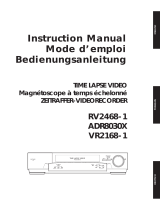
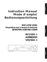
GY-DV500
SC96874-003
DV CAMCORDER
INSTRUCTIONS
*
The illustration shows the GY-DV500 DV Camcorder with the optional lens viewfinder attached.
This instruction manual is made from 100% recycled paper.
For Customer Use :
Enter below the Serial No. which is located on the body.
Retain this information for future reference.
Model No. GY-DV500
Serial No.
Thank you for purchasing this JVC product. Before operating
this unit, please read the instructions carefully to ensure the
best possible performance.
INTRODUCTION
CONTROLS,
INDICATORS AND
CONNECTORS
BASIC SYSTEM
CONNECTIONS AND
ADJUSTMENTS
POWER SUPPLY
PREPARATIONS
SETTING AND
ADJUSTMENTS
BEFORE SHOOTING
SHOOTING
OPERATION
PLAYBACK MODE
TIME CODE
OPERATION
S.S.F. (Super Scene
Finder)
USING EXTERNAL
COMPONENTS
SETUP MENU
OTHERS
FEATURES OF THE
CAMERA SECTION

2
1. Read all of these instructions.
2. Save these instructions for later use.
3. All warnings on the product and in the operating instructions should be adhered to.
4. Unplug this appliance system from the wall outlet before cleaning. Do not use liquid cleaners or aerosol cleaners.
Use a damp cloth for cleaning.
5. Do not use attachments not recommended by the appliance manufacturer as they may cause hazards.
6. Do not use this appliance near water – for example, near a bathtub, washbowl, kitchen sink, or laundry tub, in a wet
basement, or near a swimming pool, etc.
7. Do not place this appliance on an unstable cart, stand, or table. The appliance may fall, caus-
ing serious injury to a child or adult, and serious damage to the appliance.
Use only with a cart or stand recommended by the manufacturer, or sold with the appliance.
Wall or shelf mounting should follow the manufacturer’s instructions, and should use a mounting
kit approved by the manufacturer.
An appliance and cart combination should be moved with care. Quick stops, excessive force,
and uneven surfaces may cause the appliance and cart combination to overturn.
8. Slots and openings in the cabinet and the back or bottom are provided for ventilation, and to
insure reliable operation of the appliance and to protect it from overheating, these openings
must not be blocked or covered. The openings should never be blocked by placing the appliance on a bed, sofa, rug,
or other similar surface. This appliance should never be placed near or over a radiator or heat register. This appliance
should not be placed in a built-in installation such as a bookcase unless proper ventilation is provided.
9. This appliance should be operated only from the type of power source indicated on the marking label. If you are not
sure of the type of power supplied to your home, consult your dealer or local power company. For appliance designed
to operate from battery power, refer to the operating instructions.
10. This appliance system is equipped with a 3-wire grounding type plug (a plug having a third (grounding) pin). This plug
will only fit into a grounding-type power outlet. This is a safety feature. If you are unable to insert the plug into the
outlet, contact your electrician to replace your obsolete outlet. Do not defeat the safety purpose of the grounding
plug.
11. For added protection for this product during a lightning storm, or when it is left unattended and unused for long
periods of time, unplug it from the wall outlet and disconnect the antenna or cable system. This will prevent damage
to the product due to lightning and power-line surges.
12. Do not allow anything to rest on the power cord. Do not locate this appliance where the cord will be abused by
persons walking on it.
13. Follow all warnings and instructions marked on the appliance.
14. Do not overload wall outlets and extension cords as this can result in fire or electric shock.
15. Never push objects of any kind into this appliance through cabinet slots as they may touch dangerous voltage points
or short out parts that could result in a fire or electric shock. Never spill liquid of any kind on the appliance.
16. Do not attempt to service this appliance yourself as opening or removing covers may expose you to dangerous
voltage or other hazards. Refer all servicing to qualified service personnel.
17. Unplug this appliance from the wall outlet and refer servicing to qualified service personnel under the following
conditions:
a. When the power cord or plug is damaged or frayed.
b. If liquid has been spilled into the appliance.
c. If the appliance has been exposed to rain or water.
d. If the appliance does not operate normally by following the operating instructions. Adjust only those controls that
are covered by the operating instructions as improper adjustment of other controls may result in damage and will
often require extensive work by a qualified technician to restore the appliance to normal operation.
e. If the appliance has been dropped or the cabinet has been damaged.
f. When the appliance exhibits a distinct change in performance – this indicates a need for service.
18. When replacement parts are required, be sure the service technician has used replacement parts specified by the
manufacturer that have the same characteristics as the original part. Unauthorized substitutions may result in fire,
electric shock, or other hazards.
19. Upon completion of any service or repairs to this appliance, ask the service technician to perform routine safety
checks to determine that the appliance is in safe operating condition.
IMPORTANT SAFEGUARDS

3
SAFETY PRECAUTIONS
FOR USA AND CANADA
RISK OF ELECTRIC SHOCK
DO NOT OPEN
AUTION : TO REDUCE THE RISK OF ELECTRIC SHOCK,
DO NOT REMOVE COVER (OR BACK).
NO USER SERVICEABLE PARTS INSIDE.
REFER SERVICING TO QUALIFIED SERVICE PERSONNEL.
The exclamation point within an equilateral triangle is
intended to alert the user to the presence of important
operating and maintenance (servicing) instructions in
the literature accompanying the appliance.
The lightning flash with arrowhead symbol, within an
equilateral triangle is intended to alert the user to the
presence of uninsulated “dangerous voltage” within the
product's enclosure that may be of sufficient magni-
tude to constitute a risk of electric shock to persons.
INFORMATION
This equipment has been tested and found to comply with the limits
for a Class B digital device, pursuant to Part 15 of the FCC Rules.
These limits are designed to provide reasonable protection against
harmful interference in a residential installation. This equipment
generates, uses, and can radiate radio frequency energy and, if not
installed and used in accordance with the instructions, may cause
harmfull interfrence to radio communications. However, there is no
guarantee that interference will not occur in a particular installation.
If this equipment does cause harmful interference to radio or
television reception, which can be determined by turning the
equipment off and on, the user is encouraged to try to correct the
interference by one or more of the following measures:
● Reorient or relocate the receiving antenna.
● Increase the separation between the equipment and receiver.
● Connect the equipment into an outlet on a circuit different from
that to which the receiver is connected.
● Consult the dealer or an experienced radio/TV technician for help.
CAUTION
CHANGES OR MODIFICATIONS NOT APPROVED BY JVC
COULD VOID USER’S AUTHORITY TO OPERATE THE
EQUIPMENT.
INFORMATION FOR USA
THIS DEVICE COMPLIES WITH PART 15 OF THE FCC RULES.
OPERATION IS SUBJECT TO THE FOLLOWING TWO
CONDITIONS : (1) THIS DEVICE MAY NOT CAUSE HARMFUL
INTERFERENCE, AND (2) THIS DEVICE MUST ACCEPT ANY
INTERFERENCE RECEIVED, INCLUDING INTERFERENCE
THAT MAY CAUSE UNDESIRED OPERATION
INFORMATION (FOR CANADA)
RENSEIGNEMENT (POUR CANADA)
This Class B digital apparatus complies with Canadian
ICES-003.
Cet appareil numérique de la Class B est conforme à la norme
NMB-003 du Canada.
CAUTION
NOTE:
The rating plate (serial number plate) is on the top frame.
WARNING:
TO REDUCE THE RISK OF FIRE OR ELECTRIC
SHOCK, DO NOT EXPOSE THIS APPLIANCE TO
RAIN OR MOISTURE.
This unit should be used with 12V DC only.
CAUTION:
To prevent electric shocks and fire hazards, do NOT use
any other power source.
CAUTION
To prevent electric shock, do not open the cabinet. No user servicea-
ble parts inside. Refer servicing to qualified service personnel.
AVERTISSEMENT :
POUR EVITER LES RISQUES D’INCENDIE OU
D’ELECTROCUTION, NE PAS EXPOSER
L’APPAREIL A L’HUMIDITE OU A LA PLUIE.
Ce magnétoscope ne doit être utilisé que sur du courant
direct en 12V.
ATTENTION :
Afin d’eviter tout resque d’incendie ou d’électrocution,
ne pas utillser d’autres sources d’alimentation électrique.
REMARQUE :
La plaque d’identification (numéro de série) se trouve sur le panneau
arrière de l’appareil.
WARNING ON LITHIUM BATTERY
The battery used in this device may present a fire or chemical burn
hazard if mistreated. Do not recharge, disassemble, heat avobe 100°C
(212°F) or incinerate.
Replace battery with Matsushita Electric CR2032, use of another
battery may present a risk of fire or explosion.
• Dispose of used battery promptly.
• Keep away from children.
• Do not disassemble and do not dispose of in fire.

4
Thank you for purchasing the DV Camcorder GY-DV500.
These instructions are for GY-DV500U.
This unit is a MiniDV video system format camcorder.
Videocassettes which are not marked with the MiniDV
symbol cannot be used with this unit.
MAIN FEATURES
The following phenomena may occur when tapes recorded
on other units (including another GY-DV500) are recorded
or played back on this camcorder.
●
The transient section between scenes recorded on other
units and those recorded on this unit may appear
disturbed.
●
Digital noise may appear during playback due to tracking
errors.
●
Compact, lightweight design
Employment of magnesium die cast has resulted in an
operation-condition weight as low as approximately 5 kg
including lens, viewfinder, battery, and cassette.
●
DV high-quality digital format
The 4:1:1, 8-bit, 25 Mbps component digital processing of
the format ensures recording and playback with high picture
quality.
●
High sound quality thanks to PCM audio
Two types of sampling, 16-bit, 48 kHz sampling and 12-bit,
32 kHz sampling, ensure high-quality digital audio.
●
Concentrated LCD display (back-lit)
The concentrated LCD panel shows the time code and CTL
counter, tape remaining time, remaining battery power, audio
levels, VCR section setup menus, hour meter data, and a
variety of warning indications. The display is back-lit to
facilitate viewing in dark locations.
●
Time code reader/generator
The built-in time code reader/generator can be used to record
SMPTE time code and user's bits.
●
AEF (Automatic Edit Function) enables neat switching
between recorded scenes.
●
Built-in monitor loudspeaker for audio checking
The input audio can be monitored in recording or EE mode.
The playback sound can be monitored in the playback mode.
The loudspeaker also outputs an alarm tone in case an
abnormal condition occurs in the unit.
●
Rec check function for convenient recording review
●
Camera section designed with 3-CCD system for high-quality
picture
Three 1/2" CCDs with 380,000 effective pixels employed.
Digital signal processing for reproduction of DV high-quality
picture.
●
Super sensitivity F/11, 2000 lux
2000 lux standard sensitivity increased to F/11 while high S/
N is retained. Enables shooting at normal indoor illumination
eliminating the need for extra illumination.
●
LOLUX for 0.75 lux (F1.4) illumination
Employment of LOLUX mode ensures +33 dB gain. This is
ideal for difficult shooting conditions with almost no
illumination.
●
Multi-Zone Auto Iris Detection Circuit
Multi-zone auto iris detection circuit ensures optimum iris
position even in backlit conditions or when a bright subject
moves in a frame. Switch provided for selecting over or under
level.
●
Safety Zone indication in viewfinder
Three types of safety zone indicator functions provided.
●
Zebra pattern video level indication in viewfinder
●
Full Auto Shooting (FAS) function
Eliminating the need for troublesome switch or filter
operations, the FAS function automatically provides a wide
range of compatibility with shooting conditions which varies
as you move between indoors and outdoors or between bright
and dark locations.
●
Color temperature conversion filters for "3200K", "5600K",
"5600 K + ND" provided.
●
Variable scan shutter
Eliminates flicker when shooting other screen pictures than
NTSC, such as computer monitor screens.
Copes with the range from 60.1 Hz to 2084.6 Hz.
●
DV (i. LINK) connector
DV connector (4-pin) provided. Enables transfer of digital data
to other equipment provided with DV connector, such as a
non-linear editing controller.
●
S.S.F. (Super Scene Finder) function
Enables memorization of the start point and ending point of
each scene or memorization of CUE points.
●
1/2" bayonet type lens
●
Camera output, VCR playback output (composite/YC) possible
●
External sync input connector
●
Built-in color bar (SMPTE type)
●
Superior operability with shutter speed and menus selected
by dial.
●
This unit records and plays back in the SP mode.
Recording or playback in the LP mode is not possible.
●
Due to manufacturing dispersion of tapes, we
recommend not to record pictures within the first 2 to 3
minutes from the beginning of the tape.
●
Before recording important scenes, be sure to perform a
test recording and confirm that both video and audio are
recorded correctly.
●
Recorded video and audio contents are for private use.
Other use may infringe on the rights of copyright holders.
●
JVC cannot assume liabilities that may derive from the
impossibility of normal recording or playback of video or
audio due to malfunction of the camcorder or the
videocassette.

5
CONTENTS
INTRODUCTION
MAIN FEATURES ............................................................... 4
1. INTRODUCTION
1-1 Main Unit Configuration.............................................. 6
1-2 Precautions for Proper Use........................................ 7
1-3 Routine and Periodical Maintenance ......................... 8
1-4 Videocassette to be Used .......................................... 8
1-5 Battery Pack to be Used ............................................ 9
1-6 Condensation ............................................................. 9
1-7 Characteristic CCD Phenomena ................................ 9
2. CONTROLS, INDICATORS AND CONNECTORS
2-1 Front Section ............................................................ 10
2-2 Right Side Section.................................................... 12
2-3 Left Side Section ...................................................... 18
2-4 Top Section .............................................................. 19
2-5 Rear Section ............................................................ 20
2-6 Counter Display Contents ........................................ 22
2-7 Lens (optional) ......................................................... 23
2-8 1.5-Inch Viewfinder (optional)................................... 24
2-9 Indications in Viewfinder........................................... 25
• Warning LED Indicators Inside the Viewfinder ....... 25
• Viewfinder Screen Display ..................................... 25
5. PREPARATIONS
5-1 Turning the Power ON .............................................. 39
5-2 Cassette Loading and Unloading ............................. 40
5-3 Setting the Date and Time........................................ 41
6. SETTING AND ADJUSTMENTS BEFORE
SHOOTING
6-1 Camera Settings ...................................................... 42
6-2 Viewfinder Adjustment ............................................. 43
6-3 External Monitor Adjustment .................................... 43
6-4 Back Focus Adjustment............................................ 44
6-5 White Balance Adjustment ....................................... 45
• White Balance Adjustment ..................................... 45
• Full-Time Auto White Balance (FAW)..................... 45
6-6 Switch Settings of the VCR Section ......................... 46
6-7 Audio Input Signal Selection .................................... 47
6-8 Recording Level Adjustment .................................... 48
6-9 Monitoring Audio during Recording.......................... 49
7. SHOOTING OPERATION
7-1 Basic Recording Operation ...................................... 50
7-2 VCR Save Mode....................................................... 52
7-3 If Unit is Left in Record-Pause (Standby) Mode ....... 52
7-4 Checking Recorded Contents in Record-Pause Mode
(Recording Check Function) .................................... 53
8. PLAYBACK MODE
8-1 Playback Procedure ................................................. 54
8-2 Fast-Forward, Rewind .............................................. 55
8-3 Search...................................................................... 55
BASIC OPERATIONS
APPLICATION
9. TIME CODE OPERATION
9-1 Displaying Time Code .............................................. 56
9-2 Presetting and Recording of Time Code .................. 56
• Time Code Presetting Procedure........................... 57
• Presetting User's Bit Data...................................... 57
9-3 Recording Time Codes in Continuation of
Time Codes Recorded on Tape ............................... 58
9-4 Reproducing Time Codes......................................... 59
10. S.S.F. (Super Scene Finder) FUNCTION
10-1 Explanation of the S.S.F. Function ........................... 60
10-2 How to Use the S.S.F. Function................................ 61
10-3 Deleting S.S.F. Data ................................................. 62
10-4 Resetting S.S.F. Data ............................................... 62
10-5 Writing S.S.F. Data to Tape....................................... 63
10-6 Outputting S.S.F. Data.............................................. 63
PREPARATIONS
3. BASIC SYSTEM CONNECTIONS AND
ADJUSTMENTS
3-1 Basic System ........................................................... 30
3-2 Attaching the Zoom Lens (optional) ......................... 31
3-3 Attaching the Viewfinder........................................... 31
3-4 Attaching the Microphone (provided) ....................... 32
3-5 Attaching the Microphone (optional) ........................ 32
3-6 Attaching the Tripod Base (provided) ....................... 33
3-7 Inserting and Replacing Backup Lithium Batteries .. 34
4. POWER SUPPLY
4-1 AC Operation ........................................................... 35
4-2 Battery Pack Operation ............................................ 35
• Attaching a Flat Shape Type Battery Pack ............. 36
• Using an Anton-Bauer Battery Pack ...................... 37
• Remaining Battery Power Display/Precautions for
the Battery Pack..................................................... 38

6
1. INTRODUCTION
14. OTHERS
14-1 Troubleshooting........................................................ 86
• Alarm Indications ................................................... 86
• Warnings in Viewfinder........................................... 88
• Troubles with Error Code Outputs .......................... 90
• Troubles without Error Code Outputs ..................... 91
14-2 Hour Meter Display .................................................. 92
14-3 Specifications ........................................................... 93
• Optional Accessories ............................................. 94
• External Dimensions .............................................. 94
11. USING EXTERNAL COMPONENTS
11-1 Connecting a Video Component with DV Connector 64
11-2 Connecting a PC ...................................................... 65
12. SETUP MENU
12-1 VCR Setup Menu ..................................................... 66
• VCR Setup Menu Configuration............................. 66
• Displaying and Setting VCR Setup Menus............. 67
• VCR Setup Menu Contents.................................... 68
12-2 Camera Menu Screen Flow ..................................... 70
12-3 How to Select from the Camera Menu ..................... 71
12-4 VF Display Screen ................................................... 72
12-5 OPERATION Screen ................................................ 73
12-6 PROCESS Screen ................................................... 74
12-7 ADVANCED PROCESS Screen............................... 75
12-8 SKIN COLOR ADJUST Screen................................ 75
12-9 FILE MANAGE Screen............................................. 76
12-10
SETUP Screen......................................................... 77
12-11
Resetting of Camera Menu Setting Values .............. 78
13. FEATURES OF THE CAMERA SECTION
13-1 Full-Time Auto White Balance (FAW) ....................... 79
13-2 IRIS (Brightness) Adjustment................................... 80
• Adjustment of Lens Iris .......................................... 80
•
Zebra Pattern Display during Manual Adjustment......
80
13-3 Shooting the Screen Image on a Computer Monitor 81
13-4 Gain (Sensitivity) Adjustment ................................... 82
• Gain Switching ....................................................... 82
• Gain Boost under LOLUX Condition ...................... 82
13-5 Switch Setup According to Illumination and Subject 83
• Switch Functions.................................................... 83
• Full Auto Shooting (FAS) Function......................... 83
13-6 How to Use Skin Detail ............................................ 84
OTHERS
LIGHT
ON
OFF
COUNTER
CTL
TC
UB
RESET
OPERATE/WARNING
MONITOR
SELECT
STATUSSHUTTER
MENU
FILTER
1 3200k
2 5600k
3 5600k+ND
POWER
NG
GAIN
OUTPUT
WHT.BAL
VTR
ON OFF
ALARM
MONITOR
SAVE STBY
H M L
BARS CAM
AUTO KNEE
PRST A B
ON
OFF
CH-1
CH-2
AUDIO
LEVEL
AUTO IRIS LOLUX
BACK L
NORMAL
SPOT L
STRETCH
NORMAL
COMPRESS
FULL AUTO BLACK
Camcorder (GY-DV500)
The GY-DV500 configuration is as shown below.
●
The front base mount may be locked while the pin of the
tripod base is not inserted into the hole on the rear base
mount of the unit. Therefore, after mounting, make sure
that these parts are engaged properly.
●
When moving the GY-DV500 mounted on a tripod, any
impact or vibration should be avoided as this may cause
the unit to become detached and to drop from the tripod.
Be sure to remove the unit from the tripod before
transporting it.
1-1 Main Unit Configuration
CAUTION :
CR2032
3V
Lithium battery
Microphone
Head cleaning tape
Tripod base

7
1. INTRODUCTION
1-2 Precautions for Proper Use
●
Do not point the lens or viewfinder directly at the sun or other strong light source.
• Eye damage could result.
• If the lens or viewfinder is left pointed at the sun, rays may collect inside the unit and cause damage or a fire.
●
When carrying the camera, be sure to hold the carrying handle. Holding the lens or viewfinder may result in damage.
CAUTION :
●
Supply voltage
Make sure that the power is between 11 V and 15 V DC. If
the power voltage is too low, abnormal color and increased
noise may occur. Do not exceed 15 V DC in any case, or the
unit could be damaged.
●
Allowable ambient temperature and humidity
Be sure to use the unit within the allowable temperature range
of 0°C to 40°C and a relative humidity of 30% to 80%. Using
the unit at a temperature or humidity outside the allowable
ranges could result not only in malfunction but the impact on
the CCD elements could be serious as small white spots
may be generated. When storing the GY-DV500 for a long
time, the storage temperatures should be -20°C to 60°C.
●
Strong electromagnetic waves or magnetism
Where there are strong electromagnetic waves or magnetism,
for example near a radio or TV transmitter, transformer, motor,
etc., the picture may contain noise and the colors may be
incorrect.
●
Use of wireless microphone near the camera
When a wireless microphone or wireless microphone tuner
is used near the camera during recording, the tuner could
pick up noise.
●
Avoid using or placing the unit in places;
• subject to extreme heat or cold;
• with excessive dirt or dust;
• with high humidity or moisture;
• subject to smoke or vapour such as near a cooking stove;
• subject to strong vibrations or on an unstable surface.
• also do not leave the unit for long hours in a parked car
under direct sunlight or near room heating equipment.
●
Protect the unit from being splashed with water (especially
when shooting in the rain).
●
Protect the unit from being wet when shooting on a beach.
In addition, salt and sand may adhere to the camera body.
Be sure to clean the camera after use.
●
Protect the unit against penetration of dust when using it in a
place subject to sandy dust.
●
Optical performance of lens
Due to the optical performance of the lens, color divergence
phenomena (magnification chromatic aberration) may occur
at the periphery of the image. This is not a camera
malfunction.
●
Noise may appear in the viewfinder when switching between
the playback picture and the EE picture.
●
Setup level
The video signal of the unit's video output is provided with a
setup level when shipped from the factory. If you want to turn
OFF the setup level, please consult the person in charge of
professional video equipment at your nearest JVC-authorized
service agent. The setup level is never attached to the video
signal recorded on the tape.
●
Use the unit in an upright position.
If placed on its side, heat release efficiency will deteriorate,
adversely affecting the tape transport. Depending on
circumstances the tape may also be damaged.
●
Vibrations
Colors may fail to appear during VCR playback in locations
subjected to vibrations.
●
Precautions for transportation
Do not drop or hit the unit against a hard object.
●
Remove the videocassette before transporting the unit.
●
Do not insert an object other than a videocassette in the
cassette insertion slot. Be sure to close the cassette cover
when the unit is not to be used for a long period
●
Do not set the POWER switch to OFF or remove the power
cable during recording or playback. Otherwise the tape may
be damaged.
●
When the unit is not in use, be sure to set the POWER switch
to OFF in order to reduce power consumption.
●
Cleaning the body: Wipe body with a dry, soft cloth. When it is
extremely dirty, soak the cloth in a solution of neutral
detergent, wring it out and then wipe. To prevent deformation
of the body, etc. and to avoid operation hazards, do not allow
volatile liquids such as benzine and thinner to touch the body,
and do not wipe it with a cloth soaked in such a liquid.
●
The camera may be unstable in the period immediately after
the power is turned on, but this is not a malfunction.
●
If a tape containing recorded PAL signals is played back, the
GY-DV500 automatically enters the STOP mode. If this
happens, remove the videocassette so that the unit returns
to its normal state.

8
1. INTRODUCTION
Head Cleaning
●
To maintain beautiful pictures and sound, be sure to use a
head cleaning tape to clean the head periodically. (Read the
separate sheet “Precautions for Use of Head Cleaning Tape”.)
If head cleaning is not performed periodically, a type of mosaic
noise called block noise may appear in the picture or sound
may be interrupted.
●
Use the provided head cleaning tape. Do not use head
cleaning tapes other than specified. For instructions on how
to use the head cleaning tape and precautions for its use,
read the separate sheet “Precautions for Use of Head
Cleaning Tape”.
●
When dirt adheres to the heads of the GY-DV500, the
following indications appear during playback and recording
check using the RET button on the lens section.
• “RF” appears on the display panel.
• “HEAD CLOG” appears on the counter display.
• “VTR WARNING (HEAD)” appears in the viewfinder.
● If this kind of indication appears, please stop the recording.
Head cleaning is required. This indicator disappears when
the POWER is turned OFF, or when the cleaning tape is
played back.
The GY-DV500 incorporates precision mechanical parts, which will collect dirt, wear out and deteriorate as the unit is used. On the
other hand, when the unit has been used for a long period in a normal environment, the heads, drums and tape transport mechanisms
also collect dirt deposited on them. Furthermore, dust which penetrates the inside of the VCR section especially during outdoor use
will promote the wear and deterioration of mechanical parts by causing poor contact between tape and heads or failing to maintain
the video and audio quality at high levels. To prevent wear and deterioration, clean the mechanical parts using a head cleaning tape
as routine maintenance. However, cleaning with a head cleaning tape alone is not enough for cleaning the entire tape transport
mechanism, it is also recommended to apply periodical maintenance (inspection) to prevent troubles that may be caused by the
sudden occurrence of failure. As the replacement, adjustment and servicing of parts require advanced skill and equipment, please
consult the person in charge of professional video equipment at your nearest JVC-authorized service agent.
1-3 Routine and Periodical Maintenance
Periodical Maintenance
Contents : Check or replace the following mechanical parts
according to the running time.
• The maintenance contents vary depending on the operating
environment and method. Therefore, the above data should be
considered as a reference.
Time management
The accumulated running time of the unit can be confirmed
with the hour meter display (which shows the accumulated drum
running time). For details, see "HOUR METER DISPLAY" on
page 92.
For consultations related to the maintenance programming
or cost, please contact the person in charge of professional
video equipment at your nearest JVC-authorized service
agent.
V: Clean, check and adjust.
>: Clean and check. Replace as required.
v: Replace.
Running Time
500H
1000 H 1500H
2000H
Drum ass’y (including heads)
VVVv
Head cleaner >v>v
Tape guides & rollers V>>v
Rotary encoder – > – v
Belts & gears >v>v
Drive parts VV>v
Block Noise
AUD LOCK
32k
CH 1
CH 2
48k
RF
SP
MENU
OVER
OVER
40 30 20 10 0
dB
"HEAD CLOG" indicator
"RF" indicator
REC
SAVE
Switch
● Use JVC’s videocassette tapes marked with MiniDV for
this unit.
Please use DVM60 or DVM30 type videocassettes.
● Videocassettes cannot be used upside down.
● Avoid storing a videocassette with unevenly wound tape,
as this may damage the tape. Rewind it to the beginning
before placing a cassette into storage.
● Store videocassettes in a place with little humidity and good
ventilation where mould does not form.
● After a videocassette tape has been used repeatedly,
it becomes unable to maintain full performance due to
an increase in noise caused by dropouts, etc. Do not
continue to use a dirty or damaged tape, as this will
reduce the rotary head life.
● Note that if an ME80 videocassette is used at low
temperatures, block noise tends to occur due to head
contamination.
1-4 Videocassette to be Used
● Videocassette tapes marked MiniDV are provided with
a switch on the back for use in preventing accidental
erasure.
● Slide the switch to SAVE to protect the required recording
in the tape from being overwritten.
● To record on the tape, slide the switch to REC.

9
1. INTRODUCTION
Head drum
Video tape
Monitor screen
Smear
(Vertical pale streaking
appearing at high
luminous object)
High luminous object
(Electric light, sunlight, etc.)
Blooming
(Blurring in highlight)
The GY-DV500 can use any of the following battery packs.
●
Flat shape type
●
Anton-Bauer battery pack: Trimpack 13/14 Series
Magnum 13/14 Series
Compack 13/14 Series
Propack 13/14 Series
* An Anton-Bauer battery pack cannot be connected directly
to the camera. It is necessary to mount the optional battery
holder.
●
Battery holder: Anton-Bauer QRQ27
For details on how to mount the battery holder, see page
37.
●
If the unit has been cooled down in a cold place and is then
carried to a warm place, the moisture contained in the warm
air may adhere to the head drum or tape guides and be cooled
into water droplets. This phenomenon is referred to as
condensation (dewing). When this occurs, the head drum and
tape guides are covered with droplets allowing the tape to be
stuck to them, leading to tape damage.
●
Condensation occurs in the following cases:
●
When condensation occurs in this unit, the DEW indicator
on the display lights up, and the WARNING LED blinks red.
(See page 86)
To remedy, leave the unit with the power ON and wait until
the WARNING LED stops blinking red and the DEW indicator
disappears from the counter display.
• When the unit is suddenly
moved from a cold place to a
warm place.
• When a room heater has just
started or when the unit is
exposed directly to cold air from
an air conditioner.
• When the unit is placed in a very
humid place.
1-5 Battery Pack to be Used
To display the remaining battery power accurately, set the
VCR Setup Menu item No. 396 BATTERY TYPE according
to the type of the battery pack in use. (See page 69)
1-6
Condensation
Smear and Blooming
Due to the physical structure of a CCD it is possible to induce
vertical streaking (called "smear") when shooting an extremely
bright light source. Another effect is the expansion of light around
a bright light or object (called "blooming").
The CCD employed in this unit is characterized by inducing
very little smear or blooming. Nevertheless, please be careful
when shooting a bright light source.
Moire or Aliasing
Shooting stripes or fine patterns may cause a jagged effect or
a banding in fine mesh patterns.
White dots
High temperatures can cause CCD sensor pixels to malfunction
with the effect of white dots in the image. This condition is
conspicuous especially when gain is applied.
This is a characteristic of the charged-coupled device (CCD).
As far as possible, use the unit under conditions where the
temperature of the unit does not increase.
1-7 Characteristic CCD Phenomena
DEW
indicator
AUD LOCK
32k
CH 1
CH 2
48k
PB NDF
AUTO OFF DEW
HOLD
SP
MENU
OVER
OVER
40 30 20 10 0
dB
OPERATE/WARNING
Do not leave the videocassette inserted when moving the
camera under conditions where the temperature
environment changes.

10
2. CONTROLS, INDICATORS AND CONNECTORS
1
Viewfinder mount base, sliding securing ring
Mount the viewfinder on the base and secure it using the
sliding securing ring.
☞ See "Attaching the Viewfinder" on page 31.
2
[VF] Viewfinder connector (6-pin)
Connect the cable from the viewfinder here.
3
[MIC IN] Microphone input connector (XLR 3-pin)
Balanced 3-pin connector for camera microphone.
• When the camera microphone to be connected is a
phantom microphone or other type of microphone, set
the CAM MIC 48V item on the Camera Setup menu. See
page 77.
• When using a microphone with this connector, set the
AUDIO INPUT switches
7
8
on page 14 to FRONT in
accordance with the audio channel (CH1 or CH2) to be
recorded.
☞ See page 14.
1
2
3
Pin No. Function
1 GND
2 HOT
3 COLD
4
[LENS] Lens control connector
Connect 12-pin lens control cable from lens.
5
[ZEBRA] Switch
When this switch is ON, a zebra pattern is superimposed
on the viewfinder areas having video levels with a luminance
level of 70% to 80%. This pattern can be used as a reference
for manual adjustment of the lens iris.
* The zebra patterns are only displayed on the viewfinder
screen. The zebra patterns are not generated for the
MONITOR OUT or Y/C OUT output.
☞ See "Zebra Pattern during Manual Adjustment" on page
80.
• The default value is 70% - 80%. The luminance level can
be changed with the ZEBRA setting in the VF DISPLAY
Menu screen.
☞ See "ZEBRA" item on page 72.
While this switch is pressed to the SKIN AREA side, the
color tone areas specified with the SKIN DTL ADJUST item
on the ADVANCED PROCESS MENU are indicated in the
viewfinder. The switch returns to the OFF position when
released.
☞ See “How to Use Skin Detail” on page 84.
• The Skin Detail color tone areas are not indicated while
the VTR playback picture is shown in the viewfinder.
6
[VTR] VTR trigger button (record start/stop button)
Record start/stop can be effected with this button.
(It is interlocked with the VTR trigger button on the lens
section.)
7
[AUDIO LEVEL CH-1] CH-1 recording level control
Adjusts the recording level of the CH1 audio signal input.
Normally, the camera is used with the control set to the
maximum (10) position.
• To use this control, set the VCR Setup Menu item No.
246 FRONT VOLUME ENABLE to "ENABLE".
8
[AUTOWHITE./ACCU FOCUS] switch
AUTO WHITE:
• First, position a white object to occupy 80% of the centre
of the image.
• Setting this switch to the upper position ("AUTO WHT")
will provide automatic adjustment for white balance.
* It is not activated in preset, full auto shooting, full-time
auto white balance and color bar modes.
☞ See "White Balance Adjustment" on page 45.
2-1 Front Section
Pin No. Function Pin No. Function
1 RET switch 7 IRIS position
2 VCR trigger 8 IRIS A/R INPUT
3 GND 9 EXTENDER position
4
Lens AUTO/MANU control
10 ZOOM position
5 IRIS control 11 —
6 +12V DC 12 —
q
w
e
o
r
i
u
!0
!1
t
y
AUTO
WHITE
SKIN
AREA
ACCU
FOCUS
TAKE
VTR
ZEBRA
AUDIO
LEVEL CH-1
ON
OFF
VF
CAUTION:
●
The provided microphone is a phantom microphone.
Please confirm that the CAM MIC 48 V item on the
Camera SETUP Menu is set to “ON”.
●
When using a microphone other than a phantom
microphone, first set the CAM MIC 48 V item to “OFF”
before connecting the microphone. Otherwise the
microphone may be damaged.
Note:
Even when the VCR Setup Menu item No. 246 is set to
DISABLE, the recording level changes slightly when this
control is turned.

11
2. CONTROLS, INDICATORS AND CONNECTORS
ACCU-FOCUS:
• When this switch is set to "ACCU FOCUS" in the lower
position, the lens iris will be forced to open for
approximately ten seconds.
• The depth of field can be reduced and the lens focusing
can be adjusted more accurately.
9
[TAKE] button
The Super Scene Finder (S.S.F.) function retains the time
code data for IN point and OUT point or CUE point in the
unit's memory.
☞ See “S.S.F. Function on” page 60.
0
Lens mounting ring/Lens lock lever
Hold the lens and use the lever to turn the ring anticlockwise
to release lens.
To mount lens make sure the lens guide pin fits well, and
then turn the ring clockwise until firm.
☞ See "Attaching the Zoom Lens" on page 31.
!
[FILTER] Color temperature conversion filter
control knob
This knob changes the internal color temperature filter.
☞ See "Camera Settings" on page 42.
• As the automatic shutter is activated here, flicker may
appear on the screen depending on the lighting
conditions (such as a fluorescent lamp, etc.)
• This operation is not possible in the LOLUX mode.
2-1 Front Section (Cont’d)
CAUTION:

12
2. CONTROLS, INDICATORS AND CONNECTORS
1
[ALARM] Volume control
Turn to adjust the volume of the alarm tone that is output
from the monitoring loudspeaker or earphone in case of a
warning or other abnormal condition occurring with the GY-
DV500.
Turn this control anticlockwise to reduce the volume. Setting
this control to the minimum position mutes the alarm tone.
2
[MONITOR] Audio monitor volume control
Adjusts the volume of the monitoring loudspeaker and
earphone. The audio is muted when this control is set to
the minimum position.
3
[STATUS] Status/menu button
Pressing this button in the normal screen mode (condition
when menu is not shown) displays a status screen in the
viewfinder. The displayed status mode changes each time
the button is pressed.
☞ See "Status Screens" on page 25.
Pressing this button for more than 1 second in the normal
screen mode displays the Camera Menu screen in the
viewfinder. Pressing this button while the menu screen is
displayed in the viewfinder makes the menu screen
disappear.
☞ See “How to Select from the Camera Menu” on page 71.
4
[SHUTTER/MENU] dial
• Pressing this dial once in the normal screen mode
(condition when menu is not shown) displays the shutter
speed for approximately 5 seconds. When this dial is
turned upwards while the shutter speed is displayed, the
shutter speed becomes slower. When turned downwards,
the shutter speed becomes faster. The selected shutter
speed is memorised for each file. To return the memorised
shutter speed to the factory preset, press the dial one
more time while the shutter speed is displayed.
• When this dial is turned upwards or downwards while the
menu screen is displayed, the cursor (>) also moves
upwards or downwards to allow selection of items in the
menu. To change the setting value of the item, press this
dial. When the setting value starts blinking, turn this dial
upwards or downwards to change the setting.
☞ See "How to Select Camera Menus" on page 71.
5
[LOLUX] LOLUX On/Off button
This button toggles the LOLUX mode on and off.
• LOLUX gain gives extremely low light level sensitivity for
special applications. This will result in an increase of 33
dB (approximately 45 times) in the LOLUX mode.
• LOLUX operation takes priority over normal gain setting.
• If the unit is placed in the LOLUX mode when it is in full
auto shooting mode, the auto level control (ALC) (one of
the full auto shooting functions) will be made inactive, so
that the LOLUX mode is given preference (FAW still
remains active).
☞ See "GAIN BOOST UNDER LOLUX CONDITION" on
page 82.
6
[BLACK] Black stretch/black compression switch
Switches the gain for the dark section of the image.
Set to an appropriate position depending on the video signal
to be shot.
STRETCH : By stretching the signal only for the dark
section, contrast in the dark portion of the
image is enhanced.
NORMAL : Standard mode.
COMPRESS : When an entire image is relatively light and
the contrast is low, the gain of the dark
section is compressed to increase the
contrast.
7
[FULL AUTO] Full auto shooting ON/OFF button
and indicator
• This switch toggles the full auto shooting function on and
off.
• The indicator lights when in the full auto mode.
• Full auto shooting combines the auto iris, auto level control
(ALC) to automatically adjust the video signal level and
the white balance to their optimum levels.
• The iris is placed in automatic mode even if the iris mode
switch of the lens is in manual.
• The gain will vary continuously to the maximum of +12 dB.
The shutter speed will vary continuously to the minimum
of 1/240 of a second.
☞ See "Full Auto Shooting (FAS) function" on page 83.
2-2 Right Side Section
[Camera Setting Section]
1
2
3
4
5
6
7
8
9
0
A
B
C
D
RESET
OPERATE/WARNING
MONITOR
SELECT
STATUSSHUTTER
MENU
FILTER
1 3200k
2 5600k
3 5600k+ND
POWER
NG
GAIN
OUTPUT
WHT.BAL
VTR
ON OFF
ALARM
MONITOR
CH-1
CH-2
AUDIO
LEVEL
AUTO IRIS LOLUX
BACK L
NORMAL
SPOT L
STRETCH
NORMAL
COMPRESS
FULL AUTO BLACK
HML
SAVE STBY
BARS CAM
ON
OFF
AUTO KNEE
PRST A B

13
2. CONTROLS, INDICATORS AND CONNECTORS
8
[AUTO IRIS] Auto iris level switch
This switch selects the automatic iris adjustment
reference value according to the condition in which the
camera is used.
BACK. L : Under back light (Opens the iris about 1
step from the standard level.)
NORMAL: Normal condition
SPOT. L : Under spotlight (Closes the iris about 1 step
from the standard level.)
☞ See "SWITCH FUNCTIONS" on page 83.
9
[GAIN] switch
Electronically boosts the light sensitivity when there is
insufficient illumination on the subject. The boosting
level differs depending on the switch position as follows:
(Factory presets)
L : 0 dB (no boosting is applied)
M :
9 dB (boosted to approximately 3 times the original)
H :
18 dB (boosted to approximately 8 times the original)
• The boosting level for each switch position can be
changed with the OPERATION menu screen. (☞ See
page 73.)
The more the boosting level is increased, the more the
resulting image will be noisy.
0
[VTR SAVE/STBY] switch
Used to select the status of the GY-DV500 when the
power is turned ON and a videocassette is loaded.
STBY: The GY-DV500 is in the standby mode.
When a recordable videocassette is loaded, the
GY-DV500 enters the record-pause mode.
SAVE: The GY-DV500 is in the save mode.
• The status of the GY-DV500 is displayed on the Status
screen 1 in the viewfinder.
!
[OUTPUT] Color bar/Camera/Auto knee switch
This switch is used to select the output signal. When
the video signal from the shooting camera is selected,
the auto knee function is available.
CAM. AUTO KNEE ON:
Outputs the video signal from the shooting
camera. In this mode, the auto knee function is
available.
CAM. AUTO KNEE OFF:
Outputs the video signal from the shooting
camera. In this mode, the auto knee function is
not available.
BARS: Outputs the color bar signal. In this mode, the
auto knee function is not available. Set to this
position when adjusting the video monitor or
when recording the color bar signal.
AUTO KNEE function
When shooting a foreground subject, such as a human
being, etc., with a high-brightness background, if the
brightness level is set for the foreground subject, the
background image will be blurred with white. In such a
case, a clearer background is obtained when the auto
knee function is used.
It is effective especially in the following cases:
• When shooting a human being indoors with a view
to the landscape out through a window.
• When shooting a human being in the shade on a
fine day.
• When shooting a high-contrast scene.
If a fast moving high-brightness section like a car
in sunlight is shot, the auto knee function may
change the brightness of the entire image along
with the motion of the object. In this case, set the
auto knee function to OFF.
@
[WHT.BAL] White balance switch
Three white balance modes are selectable with this switch.
B : If white balance is performed with the
switch in this position, it will be
memorised into B.
A : If white balance is performed with the
switch in this position, it will be
memorised into A.
PRST (PRESET) : A non-erasable white balance setting at
3200K.
• FAW (Full-time Auto White) mode can be set to A, B or
PRESET with the OPERATION MENU (see page 73).
In the FAW mode, video color temperatures are constantly
sampled for automatic adjustment to a proper white
balance.
#
[NG] button
Pressing this button while recording or in the record-pause
mode deletes the S.S.F. data stored in the memory of the
GY-DV500 with the S.S.F. (Super Scene Finder) function.
This function is only valid in the MARK mode.
☞ See "S.S.F. (Super Scene Finder) Function" on page 60.
$
[POWER] switch
Turn the power ON and OFF with this switch.
When this switch set to ON while a videocassette is loaded,
the GY-DV500 status differs depending on the setting of
the VTR (SAVE/STBY) switch
0
.
2-2 Right Side Section [Camera Setting Section]
CAUTION:

14
2. CONTROLS, INDICATORS AND CONNECTORS
1
Monitoring loudspeaker
• Enables EE monitoring of the input audio signal during
recording, in the record-pause mode or in the stop mode.
Outputs the playback sound in the playback mode.
The sound to be output can be selected using the
MONITOR SELECT switch
4
.
• The loudspeaker volume can be adjusted with the
MONITOR volume control
2
on page 12.
The audio from the loudspeaker is not output when an
earphone is plugged into the EARPHONE jack
2
on page
20. The warning alarm tones are also output through this
loudspeaker.
☞ See “ALARM INDICATIONS” on pages 86.
2
[CH1 AUDIO LEVEL] CH1 recording level control
Adjust the recording level of the CH1 audio channel with
this control.
• To use this control, set the CH1 AUDIO SELECT switch
5 to “MANUAL”.
This control works regardless of the setting of the VCR
Setup Menu item No. 246 FRONT VOLUME ENABLE.
To use this control, set the AUDIO LEVEL CH-1 recording
level control (7 on page 10) on the front section to the
maximum (10) position, or set the VCR Setup Menu item
No. 246 FRONT VOLUME ENABLE to “DISABLE”.
3
[CH2 AUDIO LEVEL] CH2 recording level control
Adjust the recording level of the CH2 audio channel with
this control.
• This control is valid only when the CH2 AUDIO SELECT
switch
6
is set to "MANUAL".
4
[MONITOR SELECT] audio monitor selector
switch
This switch is used to select the monitor sound output from
the MONITORING LOUDSPEAKER 1 or via the
EARPHONE jack 2 on page 20.
CH-1:The CH1 channel audio is output.
MIX : CH1 and CH2 channel audio are output mixed.
CH-2:The CH2 channel audio is output.
5
[CH-1 AUDIO SELECT] selector switch
This switch is used to select the method for adjusting the
recording level of the CH-1 audio channel.
AUTO :The recording level is held at the reference level
even when sounds greater than the reference
level are input.
The recording level does not increase when the
input level is low.
MANUAL
:The recording level can be adjusted with the CH-
1 AUDIO LEVEL control
2
or the CH-1 AUDIO
LEVEL control
7
on page 10.
To use the AUDIO LEVEL CH-1 recording level
control on the front section, set the VCR Setup
Menu item No. 246 FRONT VOLUME ENABLE
to “ENABLE”.
6
[CH-2 AUDIO SELECT] selector switch
This switch is used to select the method for adjusting the
recording level of the CH-2 audio channel.
AUTO :The recording level is held at the reference level
even when sounds greater than the reference
level are input.
The recording level does not increase when the
input level is low.
MANUAL
:The recording level can be adjusted with the CH-
2 AUDIO LEVEL control
3
.
7
[CH-1 AUDIO INPUT] selector switch
This switch is used to select the input section of the CH1
audio channel.
FRONT :The sound from the MIC IN connector on the
front side section is input.
REAR :The sound from the CH-1 AUDIO IN connector
on the rear side section is input.
8
[CH-2 AUDIO INPUT] selector switch
This switch is used to select the input section of the CH2
audio channel.
FRONT :The sound from the MIC IN connector on the
front side section is input.
REAR :The sound from the CH-2 AUDIO IN connector
on the rear side section is input.
[Audio Setting Section]
2-2 Right Side Section (Cont'd)
qwe
r
ty
ui
LIGHT
ON
OFF
COUNTER
CTL
TC
UB
RESET
OPERATE/WARNING
MONITOR
SELECT
STATUSSHUTTER
MENU
FILTER
1 3200k
2 5600k
3 5600k+ND
POWER
NG
GAIN
OUTPUT
WHT.BAL
VTR
ON OFF
ALARM
MONITOR
CH-1
CH-2
AUDIO
LEVEL
AUTO IRIS LOLUX
BACK L
NORMAL
SPOT L
STRETCH
NORMAL
COMPRESS
FULL AUTO BLACK
HML
SAVE STBY
BARS CAM
ON
OFF
AUTO KNEE
PRST A B
CH-1
CH-2
AUDIO
LEVEL
CH-1 CH-2
AUTO
MANUAL
FRONT
REAR
AUDIO SELECT
AUDIO INPUT
CAUTION:
Make sure to move switches all the way. Do not leave a
switch stopped in a midway position. Noise will be
generated and operation irregularities will occur.

15
2. CONTROLS, INDICATORS AND CONNECTORS
LIGHT
ON
OFF
COUNTER
CTL
TC
UB
RESET
OPERATE/WARNING
MONITOR
SELECT
STATUSSHUTTER
MENU
FILTER
1 3200k
2 5600k
3 5600k+ND
POWER
NG
GAIN
OUTPUT
WHT.BAL
VTR
ON OFF
ALARM
MONITOR
CH-1
CH-2
AUDIO
LEVEL
AUTO IRIS LOLUX
BACK L
NORMAL
SPOT L
STRETCH
NORMAL
COMPRESS
FULL AUTO BLACK
HML
SAVE STBY
BARS CAM
ON
OFF
AUTO KNEE
PRST A B
TC GENERATOR
FREE
REC
PRESET
REGEN
CH-1
CH-2CH-1
CH-2
CH-1 CH-2
CONTINUE MENU
PRESETADVANCESHIFTHOLD
AUTO
MANUAL
FRONT
REAR
DATA SET
SELECTITEMGROUP
AUDIO SELECT
AUDIO INPUT
AUDIO
LEVEL
LITHIUM BATT.
qy
w
ui
o
ert
1
[MENU] button
Press this button to enter the VCR setup menu mode.
When the VCR setup menu mode is engaged, the "MENU"
indicator in the LCD display lights and the counter display
and viewfinder display are changed to the menu indication.
In the VCR setup menu mode, pressing this button resumes
the normal mode.
2
[HOLD/GROUP] button
• Press this button when presetting the time code or user's
bit. The presently displayed data is held (the "HOLD"
indicator lights on the display) and the leftmost digit of
the counter blinks. Pressing this button during presetting
of time code or user's bit cancels the operation and recalls
the previous display contents.
• In setup menu mode, this button is used to select the
menu group.
3
[SHIFT/ITEM] button
• During presetting of time code or user's bit, press this
button to select the digit to be set. Each press of the button
shifts the digit to be set (which blinks) to the right.
• In setup menu mode, this button is used to select the
menu item.
4
[ADVANCE/SELECT] button
• During presetting of time code or user's bit, press to select
the value of the digit to be set. Each press of the button
increases the number by 1.
• In setup menu mode, this button is used to select the
value of a menu item.
5
[PRESET/DATA SET] button
• During presetting of time code or user's bit, press to save
the set value in the preset memory. The set time code or
user's bit will be preset in the time code generator.
• In setup menu mode, this button is used to confirm the
menu item setting and save the data in the memory.
• For details of the presetting of time code or user's
bit, see page 56.
• For details on the setup menus, see page 67.
[VCR Setup Block]
6
[CONTINUE] button
If this button is pressed simultaneously with the LOG button
8 on page 19 during the stop mode, the tape winds to the
last S.S.F. data OUT point.
☞ See “Scene End Cue Up Function” on page 63.
TIME CODE GENERATOR setting switches
7
[PRESET/REGEN] switch
Toggles the time code generator mode between PRESET
and REGEN.
PRESET: Preset mode. Set to this position when newly
presetting and recording the time code.
REGEN : Regeneration mode, in which the unit reads
existing time codes on the tape and records time
codes in continuation of the existing ones. Set to
this position when you want to add additional time
codes to time codes already recorded on the
tape.
8
[REC/FREE] run switch
Selects the time code running mode while the time code
generator is in preset mode. This switch is not effective in
the REGEN mode.
REC : The time code runs only during recording. This
position allows you to record continuous time
codes when recording scenes one after another.
FREE : The time code runs permanently.
* If this position is used when recording scenes one after
another, the time codes become discontinuous at the
change points between scenes.
9
Lithium Battery Installation Compartment
Install a lithium battery (CR2032) in this compartment. The
battery is used for the backup of the time code and time
date. The GY-DV500 is delivered without the battery
installed.
The provided lithium battery is for test use. It is recommended
to install a new lithium battery. A new lithium battery can
power the backup for about one year. See "How to Replace
Backup Lithium Batteries" on page 34.
2-2 Right Side Section (Cont'd)

16
2. CONTROLS, INDICATORS AND CONNECTORS
LIGHT
ON
OFF
COUNTER
CTL
TC
UB
RESET
OPERATE/WARNING
MONITOR
SELECT
STATUSSHUTTER
MENU
FILTER
1 3200k
2 5600k
3 5600k+ND
POWER
NG
GAIN
OUTPUT
WHT.BAL
VTR
ON OFF
ALARM
MONITOR
CH-1
CH-2
AUDIO
LEVEL
AUTO IRIS LOLUX
BACK L
NORMAL
SPOT L
STRETCH
NORMAL
COMPRESS
FULL AUTO BLACK
HML
SAVE STBY
BARS CAM
ON
OFF
AUTO KNEE
PRST A B
E
REV FWD
FBATT
H
HM
MSF
REMAIN
AUD LOCK
32k
CH 1
CH 2
48k
PB NDF
AUTO OFF DEW
L iRFSERVO
HOLD
SP
MENU
OVER
OVER
40 30 20 10 0
dB
3
4
6
7
8
9
0
A
B
CD
EF5
12
[VCR Display Section]
☞ See “VCR Setup Menu Contents” on page 69.
5
Audio level meters
Show the audio input level of the CH-1 and CH-2 channels
in the record mode or EE mode.
In the playback mode, the meters show the playback audio
level.
"OVER" lights in case of excessive input.
Immediately after the power is switched ON, the level
meters may fluctuate. This is not a malfunction.
6
32K/48K sampling frequency indication
Indicates whether audio recording or playback occurs with
12-bit, 32 kHz sampling or 16-bit 48 kHz sampling.
• In the recording mode, the sampling frequency is set using
the VCR Setup Menu item No. 245 SAMPLING RATE.
In the playback mode, the indication conforms to the
sampling rate of the recorded sound.
7
[AUD LOCK] indicator
Indicates whether the audio signal is locked to the video
signal during recording and playback.
8
[MENU] indicator
Appears when the MENU button
1
on page 15 is pressed
to select the VCR Setup Menu.
9
SP indicator
Indicates the tape speed in record mode.
0
Cassette indicator
Lights when the unit is loaded with a
videocassette. Blinks during ejection or tape
loading.
!
[REMAIN] indicator
The remaining tape time (minutes and seconds) is shown.
For details, see page “Remaining Tape Time Display” on
page 22.
2-2 Right Side Section (Cont'd)
CAUTION:
1
[OPERATE/WARNING] indicator
Normally lights green.
Lights orange during the VTR SAVE (tape protect) mode.
This indicator lights or blinks in red in the case of a warning
condition related to the remaining tape time, remaining
battery power or other abnormal condition in the unit.
For details, see "ALARM INDICATIONS" on pages 86.
2
[RESET] button
• Press to reset the CTL counter value.
• Pressing the button during presetting of time code or
user's bit resets the time code or user's bit data to
"00:00:00:00".
3
[LIGHT] switch
Turns the illumination of the back-lit display ON or OFF.
ON : The display is illuminated.
OFF : The display is not illuminated.
(Keep this switch at OFF during battery operation of the
GY-DV500 or when it is required to reduce the power
consumption for some reason.)
4
[COUNTER] switch
Selects the contents displayed on the LCD counter display.
The displayed contents when TC or UB is set can be
selected using the VCR Setup Menu item No. 516 DISPLAY
SELECT.
CTL : Set to this position to display the CTL counter.
TC : Set to this position to display time codes or for
presetting the time code. (When the Menu item No.
516 DISPLAY SELECT is set to “TC”.)
Time (Hour, Min., Sec.) is displayed. (When the Menu
item No. 516 DISPLAY SELECT is set to “CLOCK”.)
UB : Set to this position to display the user's bits of time
codes or presetting the user's bit. (When the Menu
item No. 516 DISPLAY SELECT is set to “TC”.)
Date (Month, Day, Year) is displayed. (When the Menu
item No. 516 DISPLAY SELECT is set to “CLOCK”.)
Note:
When a videocassette is loaded and the VTR switch is
set to SAVE mode, the illumination will go out even if the
backlight is ON.

17
2. CONTROLS, INDICATORS AND CONNECTORS
^
Warning indicators
n [AUTO OFF] indicator
Lights when a non-recoverable error (e.g. tape winding
error, drum stopped, etc.) occurs with the unit. This
indicator also lights if condensation occurs.
☞ See "TROUBLES WITH ERROR CODE OUTPUTS"
on page 90.
n [DEW] indicator
Lights when condensation (dewing) occurs on the drum
or other mechanism in the unit.
The unit rejects all operations while this indicator is lit.
When the condensation has disappeared, the indicator
turns off and the unit accepts operations again.
n [SERVO] indicator
Lights in the case of trouble with the drum servo during
recording to indicate that normal recording is not being
accomplished.
n [RF] indicator
Lights when the video head is clogged. Head clogging is
detected during playback and recording check using the
RET button on the lens section. Note that it is not detected
during recording.
* Should this indicator light up, clean the head using the
provided head cleaning tape. For instructions on head
cleaning tape, read the separate sheet “Precautions for
Use of Head Cleaning Tape”.
n [Li] Lithium battery indicator
Lights and indicates the necessity of replacement when
the lithium battery that backs up data of the built-in time
code generator is nearly exhausted.
☞ See "How to Replace Backup Lithium Batteries" on
page 34.
REV FWD
@
Tape transport direction indicators
One of the indicators lights according to the
tape transport direction.
is displayed in the record-pause
mode and in the still picture mode.
#
Remaining Battery Power Display
The 7-dot segment bar display shows the remaining battery
power.
* To display the remaining battery power accurately, set
the VCR Setup Menu item No. 396 BATTERY TYPE
according to the type of the battery pack in use.
☞ See "Remaining Battery Power Display" on page 22.
$
Counter display
• Usually, this section shows the data of the CTL counter,
time code or user's bit. The display mode can be selected
with the 4 COUNTER switch.
• Displays the VCR setup menu data when the GY-DV500
is in the VCR setup menu mode by pressing the MENU
button
1
on page 15. The VCR setup menu includes the
hour meter (accumulated drum operating time).
• This section shows an error code when an abnormal
condition occurs with the unit.
☞ See "Counter Display Contents" on page 22.
☞ See "TROUBLES WITH ERROR CODE OUTPUTS"
on page 90.
%
Section for time code related indications
n [PB] Time code playback indicator
Lights when the time code is in playback mode.
n [NDF] Non-drop frame indicator
Lights when the internal time code generator or the
playback time code framing mode is non-drop frame. “DF”
is displayed in the drop-frame mode.
• It never lights when the CTL counter is displayed.
n [HOLD] indicator
Lights when the time code generator display is held by
pressing the HOLD button in the time code setting block.
The time code or user's bit can be preset while this
indicator is lit.
☞ See “Displaying Time Code” on page 56.
2-2 Right Side Section (Cont'd)

18
2. CONTROLS, INDICATORS AND CONNECTORS
• The camera cannot be synchronized with a VCR
playback signal.
• When the power is switched ON while an external sync
signal is input, the screen moves in a vertical direction
for a few seconds. This is not a malfunction.
• Only for the combined H (horizontal)/V (vertical)
synchronizing signal. Synchronization with the SC (sub-
carrier) of the input signal is not possible.
Even if SC adjustment is performed, a phase shift will
take place at the time of power on/off. The SC phase
must be adjusted each time the power is turned on.
• If the external sync signal is disrupted during recording,
the “SYNC INH” (SYNC INHIBIT) indicator is displayed
on the counter display and recording stops.
• If the external sync signal is disrupted during playback,
playback of the disturbed video image continues.
Start playback again after synchronization is obtained
and the signal is stabilized.
[VTR REMOTE] connector
A part of the unit's functions can be controlled externally. To
remote control the unit using the control signal of this
connector, the VCR Setup Menu item No. 050 REMOTE
SELECT must be set to "RS232C".
For details, please consult your JVC dealer.
8
Microphone attachment holes
For attaching the microphone holder KA-A50 (optional).
☞ See "Attaching the Microphone (optional)" on page 32.
Note:
• When a cable is connected to the VTR REMOTE
connector, the VTR Setup Menu is not displayed in
the viewfinder. Make settings on the VTR Setup Menu
while the cable is not connected.
• When a cable is connected to the VTR REMOTE
connector, the VCR operation mode will not be
displayed correctly on the Status 1 screen in the
viewfinder.
VTR
REMOTE
SYNC IN
MIC IN
LENS
TEST OUT
Y/C OUTMONITOR OUT
LINE OUT
CH-1 CH-2
PUSH
DV CAMCORDER
GY-DV500
q
w
e
r
t
y
u
i
1
Cassette cover
Pressing the EJECT switch on top of the section opens this
cover so that a videocassette can be inserted or removed
from the unit. The cover can be locked automatically by
pushing and closing it.
* If the cassette cover is not closed, the GY-DV500 will
remain inoperative.
To prevent penetration of foreign objects into the unit,
do not leave the unit with the cassette cover open.
2
[MONITOR OUT] monitor output connector (BNC)
• Composite video signal output connector.
• Setup level signals are output.
An EE image or the playback image is output through the
VCR section.
An EE image is output during other modes than the
playback mode.
* Data for the Camera and VCR setup menus or time code
is not output.
• A setup level signal is not attached to the IEEE1394
signal’s EE image.
3
[Y/C OUT] connector (4P)
Separate YC video signal output connector.
4
[LINE OUT CH-1/CH-2] connector (RCA)
Output connector for audio signals.
• Outputs the input audio signal in the record and stop
modes.
• Outputs the playback audio signal in the playback mode.
• Alarm sound is not output.
5
[TEST OUT] connector (BNC)
Composite video signal output connector.
Outputs the camera image.
Setup level signals are output.
6
[SYNC.IN] connector (BNC)
For inputting the sync signal when the GY-DV500’s camera
image is synchronized with an external component.
2-3 Left Side Section
Memo:
Memo:
To prevent penetration of foreign objects into the unit,
do not leave the unit with the cassette cover open.

19
2. CONTROLS, INDICATORS AND CONNECTORS
PUSH OPEN
LOG REW FF
PLAY STILL
STOP
EJECT
w
ertyui
q w
1
[EJECT] switch
Slide to the side when inserting or ejecting the
videocassette. Sliding this switch opens the cassette cover.
If the switch is moved while the power is off, the cassette
cover opens but it is not possible to insert or eject the
cassette.
2
Operation cover
Open this cover when operating in the playback mode.
Otherwise, keep this cover closed.
3
[PLAY] button
Press to start playback. In play mode, the unit outputs the
video and audio signals of normal playback and the LED
indicator above the PLAY button lights.
* If the auto tracking is active at the moment the play mode
is entered, the playback video will be interfered with digital
noise.
4
[STOP] button
Press to enter stop mode. The drum keeps rotating in stop
mode. However, when stop mode has continued for about
30 minutes, the unit enters the tape protect mode, in which
the drum stops rotation and the tape tensioner is released.
It takes more time than usual to enter the record or play
mode from the tape protect mode.
* The time until the tape protect mode is initiated can be
set to 3 or 30 minutes with the VCR Setup Menu item No.
307 LONG PAUSE TIME. When used in a cold
environment, the setting will be 3 minutes regardless of
the setting on the VCR Setup Menu.
☞ See page 69.
5
[STILL] button
Press to enter the still picture mode during playback or in
the search or stop mode.
When the still picture mode has continued for about 30
minutes, the unit automatically switches to the stop mode.
(Tape protect mode)
* The time until the tape protect mode is initiated can be
set to 3 or 30 minutes with the VCR Setup Menu item No.
307 LONG PAUSE TIME.
When used in a cold environment, the setting will be 3
minutes regardless of the setting on the VCR Setup Menu.
6
[REW] button
Press to rewind the tape.
• Pressing the button in stop or fast forward mode initiates
the rewind mode. The LED indicator above the REW
button lights in this mode.
• Pressing the button during playback, still or forward search
initiates reverse search at about 10 times the normal play
speed. The LED indicators above the PLAY and REW
buttons light during reverse search.
7
[FF] button
Press to fast forward tape.
• Pressing the button in stop or rewind mode initiates fast
forward mode. The LED indicator above the FF button
lights in this mode.
• Pressing the button during playback, still or reverse search
initiates forward search at about 10 times the normal play
speed. The LED indicators above the PLAY and FF
buttons light during forward search.
8
[LOG] button
• When the REW button is pressed while this button is kept
pressed, the S.S.F. data stored in the unit’s memory are
written to the tape. The LED indicator above the LOG
button lights while S.S.F. data is being written to the tape.
• When the CONTINUE button (6 on page 15) is pressed
while this button is kept pressed in the stop mode, the
tape winds to the S.S.F. data’s last OUT point, after which
the unit enters the record-pause mode. (Scene End Cue
Up)
The FF button’s LED blinks during Scene End Cue Up.
☞ See "Writing S.S.F. Data to Tape" on page 63.
2-4 Top Section
CAUTION:
• Only the EJECT switch and STOP button work during
recording.
• If the cassette cover is open, all operations are
rejected.

20
2. CONTROLS, INDICATORS AND CONNECTORS
1 4
32
No. Signal
GND
—
—
+12V
1
2
3
4
(Surface profile)
14
23
No. Signal
GND
—
—
DC +12V (power through)
1
2
3
4
1
[DV] connector
Using a DV cable (optional), a digital video component with
DV connector can be connected here.
This connector is used for input and output of the DV signal
or to input the VCR control signal from the digital video
component with DV connector.
• To record the DV signal from this connector, set the VCR
Setup Menu item No. 126 INPUT SELECT to "IEEE1394".
• To remote control the VCR with a VCR control signal from
this connector, set the VCR Setup Menu item No. 050
REMOTE SELECT to "IEEE1394".
2
[EAR.] earphone jack
This is a stereo mini-jack for connecting an audio monitoring
earphone. Plug in an earphone or headphone with a 3.5
mm diameter plug. (Monaural mini jack)
The earphone can also be used to monitor alarm tones
depending on situations.
The sound from the monitoring loudspeaker is interrupted
when an earphone is connected here.
3
[DC OUTPUT] connector
Power output connector to a wireless microphone
transmitter, etc. The supply voltage is identical to the voltage
supplied to the unit (DC 12V max. 0.1 A).
4
[DC INPUT] connector (XLR 4-pin)
Power input connector for 12 V DC. Connect with the AA-
P250 optional AC power adapter. When a cable is connected
here, the power supply from the battery pack is interrupted
and the source is switched to the power supplied through
this connector.
5
[CH-1 AUDIO IN] CH-1 audio input connector (XLR
3-pin)
Connect the external audio equipment or microphone to
this connector. Set the CH-1 AUDIO IN LINE/MIC select
switch
8
according to the connected equipment.
The audio signal input through this connector is recorded
on the CH-1 audio channel. To record the audio of this
connector, set the CH-1 AUDIO INPUT switch
7
on page
14 to "REAR".
(AUDIO IN connector)
2-5 Rear Section
Bottom side
TALLY
DV
AUDIO IN
CH-1
DC INPUT
EARPHONE
DC OUTPUT
LINE MIC
+48V
ON
CH-2
LINE MIC
+48V
ON
VTR
REMOTE
SYNC IN
MIC
LEN
S
TEST OUTPUT
Y/C OUT MONITOR OUT
LINE OUT
CH-1 CH-2
PUSH
DV CAMCORDER
GY-DV500
BREAKER
q
w
e
rt y
u
o
i
0
!1
B
Memo:
Only the left-channel sound is heard when a stereo mini-
jack is used.
No. Signal
GND
HOT
COLD
1
2
3
2
1
3
/