Food flavor and aroma are usually so closely related
that it is difficult, if not impossible, to separate them.
There is also an important, inseparable relationship
between cleanliness and food flavor. Cleanliness, top
operating efficiency, and appearance of equipment
contribute considerably to savory, appetizing foods.
Good equipment that is kept clean, works better and
lasts longer.
Most food imparts its own particular aroma and
many foods also absorb existing odors. Unfortunately,
during this absorption, there is no distinction between
GOOD and BAD odors. The majority of objectionable
flavors and odors troubling food service operations are
caused by bacteria growth. Sourness, rancidity, musti-
ness, stale or other OFF flavors are usually the result of
germ activity.
The easiest way to insure full, natural food flavor is
through comprehensive cleanliness. This means good
control of both visible soil (dirt) and invisible soil (germs).
A thorough approach to sanitation will provide essential
cleanliness. It will assure an attractive appearance of
equipment, along with maximum efficiency and utility.
More importantly, a good sanitation program provides
one of the key elements in the prevention of food-borne
illnesses.
A controlled holding environment for prepared
foods is just one of the important factors involved in
the prevention of food-borne illnesses. Temperature
monitoring and control during receiving, storage,
preparation, and the service of foods are of equal
importance.
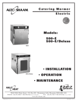
The most accu-
rate method of
measuring safe
temperatures of
both hot and
cold foods is by
internal product
temperature. A
quality ther-
mometer is an
effective tool
for this
purpose, and should be routinely used on all products
that require holding at a specific temperature.
A comprehensive sanitation program should focus
on the training of staff in basic sanitation procedures.
This includes personal hygiene, proper handling of raw
foods, cooking to a safe internal product temperature,
and the routine monitoring of internal temperatures
from receiving through service.
Most food-borne illnesses can be prevented through
proper temperature control and a comprehensive
program of sanitation. Both these factors are important
to build quality service as the foundation of customer
satisfaction. Safe food handling practices to prevent
food-borne illness is of critical importance to the health
and safety of your customers. HACCP, an acronym for
Hazard Analysis (at) Critical Control Points, is a quality
control program of operating procedures to assure food
integrity, quality, and safety. Taking steps necessary to
augment food safety practices are both cost effective and
relatively simple. While HACCP guidelines go far
beyond the scope of this manual, additional information
is available by contacting the USDA/FDA Food-borne
Illness Education Information Center at (301)504-6803.
Chefs, cooks and other specialized food service personnel
employ varied methods of cooking. Proper holding tempera-
tures for a specific food product must be based on the moisture
content of the product, product density, volume, and proper
serving temperatures. Safe holding temperatures must also be
correlated with palatability in determining the length of holding
time for a specific product.
Halo Heat maintains the maximum amount of product mois-
ture content without the addition of water, water vapor, or
steam. Maintaining maximum natural product moisture
preserves the natural flavor of the product and provides a more
genuine taste. In addition to product moisture retention, the
gentle properties of Halo Heat maintain a consistent tempera-
ture throughout the cabinet without the necessity of a heat distri-
bution fan, thereby preventing further moisture loss due to evap-
oration or dehydration.
In an enclosed holding environment, too much moisture
content is a condition which can be relieved. A product
achieving extremely high temperatures in preparation must be
allowed to decrease in temperature before being placed in a
controlled holding atmosphere. If the product is not allowed to
decrease in temperature, excessive condensation will form
increasing the moisture content on the outside of the product.
Most Halo Heat Holding Equipment is provided with a ther-
mostat control between 60° and 200°F (16° to 93°C). If the
unit is equipped with vents, close the vents for moist holding and
open the vents for crisp holding.
If the unit is equipped with a thermostat indicating a range
of between 1 and 10, use a metal-stemmed indicating ther-
mometer to measure the internal temperature of the product(s)
being held. Adjust the thermostat setting to achieve the best
overall setting based on internal product temperature
.
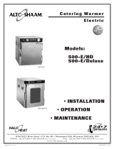
INTERNAL FOOD PRODUCT TEMPERATURES
HOT FOODS
DANGER ZONE 40° TO 140°F(4° TO 60°C)
CRITICAL ZONE 70° TO 120°F (21° TO 49°C)
SAFE ZONE 140° TO 165°F (60° TO 74°C)
COLD FOODS
DANGER ZONE ABOVE 40°F (ABOVE 4°C)
SAFE ZONE 36°F TO 40°F(2°C TO 4°C)
FROZEN FOODS
DANGER ZONE ABOVE 32°F (ABOVE 0°C)
CRITICAL ZONE 0° TO 32°F (-18° TO 0°C)
SAFE ZONE 0°F OR BELOW (-18°C OR BELOW)
#828 Operation & Care Manual - 3.
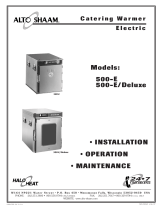
HOLDING TEMPERATURE RANGE
MEAT FAHRENHEIT CELSIUS
BEEF ROAST — Rare 140°F60°C
BEEF ROAST — Med/Well Done 160°F71°C
BEEF BRISKET 160°— 175°F71°— 79°C
CORN BEEF 160°— 175°F71°— 79°C
PASTRAMI 160°— 175°F71°— 79°C
PRIME RIB — Rare 140°F60°C
STEAKS — Broiled/Fried 140°— 160°F60°— 71°C
RIBS — Beef or Pork 160°F71°C
VEAL 160°— 175°F71°— 79°C
HAM 160°— 175°F71°— 79°C
PORK 160°— 175°F71°— 79°C
LAMB 160°— 175°F71°— 79°C
POULTRY
CHICKEN — Fried/Baked 160°— 175°F71°— 79°C
DUCK 160°— 175°F71°— 79°C
TURKEY 160°— 175°F71°— 79°C
GENERAL 160°— 175°F71°— 79°C
FISH/SEAFOOD
FISH — Baked/Fried 160°— 175°F71°— 79°C
LOBSTER 160°— 175°F71°— 79°C
SHRIMP — Fried 160°— 175°F71°— 79°C
BAKED GOODS
BREADS/ROLLS 120°— 140°F49°— 60°C
MISCELLANEOUS
CASSEROLES 160°— 175°F71°— 79°C
DOUGH — Proofing 80°— 100°F27°— 38°C
EGGS —Fried 150°— 160°F66°— 71°C
FROZEN ENTREES 160°— 175°F71°— 79°C
HORS D'OEUVRES 160°— 180°F71°— 82°C
PASTA 160°— 180°F71°— 82°C
PIZZA 160°— 180°F71°— 82°C
POTATOES 180°F82°C
PLATED MEALS 180°F82°C
SAUCES 140°— 200°F60°— 93°C
SOUP 140°— 200°F60°— 93°C
VEGETABLES 160°— 175°F71°— 79°C
THE HOLDING TEMPERATURES LISTED ARE SUGGESTED GUIDELINES ONLY
SANITATION GUIDELINES GENERAL HOLDING GUIDELINES