Page is loading ...

#824 • 5/2002
PRINTED IN U.S .A .
HOT FOOD DISPLAY CABINETS
MODELS: 600-LVD
600-LVD/PT
OPERATION and CARE MANUAL
®
COOK/HOLD/SERVE SYSTEMS
W164 N9221 Water Street
●
P.O. Box 450
●
Menomonee Falls, Wisconsin 53052-0450 U.S.A.
PHONE: 262.251.3800 FAX: 262.251.7067 • 800.329.8744 U.S.A. ONLY WEBSITE:
800.558.8744 U.S.A./CANADA 262.251.1907 INTERNATIONAL www.alto-shaam.com

#824 Operation & Care Manual • 1.
RECEIVING AND INSPECTION
The Alto-Shaam Holding Cabinet has
been thoroughly tested, checked for
calibration, and inspected to insure only
the highest quality cabinet is provided.
When you receive your unit, check for
any possible shipping damage and report
it at once to the delivering carrier.
The cabinet, complete with unattached items and accessories,
may be delivered in one or more packages. Check to ensure that all
the following items have been received as standard with each unit.
12: CHROME PLATED WIRE SHELVES
Save all the information and instructions packed inside the
cabinet. Complete and return the warranty card to the factory as
soon as possible to assure prompt service in the event of a warranty
parts and labor claim.
NOTE: All claims for warranty must include the full model
number and serial number of the cabinet.
ELECTRICAL INSTALLATION
1. An identification tag is permanently mounted on the cabinet.
2. Position the unit so that the power supply cord is easily
accessible in case of an emergency.
3. Plug the cabinet into a properly grounded receptacle ONLY.
If necessary, a proper receptacle or outlet configuration, as
required for this unit, must be installed by a licensed electrician
in accordance with applicable, local electrical codes.
HEATING CHARACTERISTICS
The cabinet is equipped with a special, low-heat-density,
heating cable. Through the Halo Heat concept, the heating cable
is mounted against the walls of the warming compartment to
provide an evenly applied heat source controlled by a thermostat.
The design and operational characteristics of the cabinet eliminates
the need for a moisture pan or a heat circulating fan. Through
even heat application, the quality of a food product is maintained
up to several hours.
START-UP
Read all instructions in this manual thoroughly before use of this
unit. Keep this manual in a safe and easily accessible area.
1. In order to maintain standards established by the National
Sanitation Foundation, all counter-mounted equipment must
be secured flush to the counter and the entire base sealed to the
counter with NSF approved sealant or equipped with 4"
(102mm) legs to provide minimum unobstructed space beneath
the unit. These legs are supplied with the unit. Warranty will
become null and void if these directions are not followed.
2. Before operating the unit, clean both the interior and exterior of
the cabinet with a clean, damp cloth and mild
soap solution. Rinse carefully.
3. Clean and install the cabinet wire shelves.
CARE and CLEANING
The cleanliness and appearance of this equipment
will contribute considerably to operating efficiency
and savory, appetizing food. Good equipment that is kept clean
works better and lasts longer.
CLEAN THE DISPLAY CABINET DAILY
:
1. Disconnect the cabinet from the power source.
2. Remove all detachable items such as wire shelves. Clean these
items separately.
3. Clean the interior metal surfaces of the cabinet
with a clean, damp cloth and any good alkaline
or alkaline chlorinated based commercial
detergent or grease solvent at the recommended
strength. Use a plastic scouring pad or oven
cleaner for difficult areas. Avoid the use of
abrasive cleaning compounds, chloride based
cleaners, or cleaners containing quaternary
salts. Rinse carefully to remove all residue and
wipe dry.
NOTE: Never use hydrochloric acid (muriatic acid) on
stainless steel.
4. To help maintain the protective film coating on
polished stainless steel, clean the exterior of the cabinet
with a cleaner recommended for stainless steel surfaces.
Spray the cleaning agent on a clean cloth and wipe with
the grain of the stainless steel.
5. Clean the glass with a window cleaner.
Always follow appropriate state or local health (hygiene) regulations
regarding all applicable cleaning and sanitation requirements for
equipment.
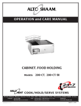
— HOT DISPLAY CABINETS
EXAMPLE
SERIAL NUMBER AND WARRANTY CODE
MAXIMUM RATED
WATTAGE
IDENTIFICATION MODEL NUMBER
MAXIMUM RATED VOLTAGE MAXIMUM RATED FREQUENCY
MODEL
SERIAL NO. WATTS
1 PH
VOLTS
xxx-xx
xxxx-xx xxxx
xx
HZxxx
AC
ALTO-SHAAM INC. MILW. WI. PAT. NO. 3521030
ENSURE POWER SOURCE
MATCHES VOLTAGE STAMPED
ON UNIT NAMEPLATE
®
At no time should the inside or outside
of the cabinet be washed down, flooded
with water or liquid solution. NEVER
STEAM CLEAN. Do not use water
jet to clean. Severe damage
or electrical hazard could result,
voiding the warranty.

600-LVD • OPERATIONAL PROCEDURES
#824 Operation & Care Manual • 2.
SET
prg
!
ERROR CODE
INDICATOR L.E.D.
HEAT
INDICATOR L.E.D.
CHAMBER
TEMPERATURE
L.E.D.
TEMPERATURE
SET
BUTTON
L.E.D.1
INCREASE / DECREASE
BUTTON
200
POWER
ON/OFF
ROCKER SWITCH
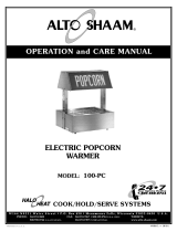
Thermostat Control Description and Function
The L.E.D., Light Emitting Diode, referred to is an electronic
device providing illumination.
The control has a three-digit L.E.D. display. When the
warming cabinet is in operation, the L.E.D. will show the
chamber's internal temperature. The display will also show
programming and diagnostic information.
ON/OFF Rocker Switch
The Power On/Off Rocker Switch positions
may be marked with the international "
I" for
On and "O" for Off.
UP/DOWN Arrow Rocker Button
The UP/DOWN arrow rocker button is used to
increase or decrease the set-point temperature. The
minimum set-point temperature is 90°F (32°C) while
the maximum set-point temperature is 200°F (93°C).
SET Button
The SET button is used to display the current
set-point temperature or program a new set-point
temperature. Pushing the SET button once will
display the set-point temperature value for five
seconds. Holding the SET button allows the
programming mode to become active.
L.E.D. Display
The L.E.D. display will show the set-point
temperature value when programming, or the
warming chamber's temperature when calling
for heat. When programming a new set-point
temperature, the L.E.D.1 indicator with blink.
When a new set-point temperature is chosen,
the Chamber Temperature L.E.D. will flash
three times to confirm.
POWER
ON/OFF
ROCKER SWITCH
SET
°F
CHAMBER
TEMPERATURE
L.E.D.
L.E.D.1
200
HEAT INDICATOR L.E.D.
The Heat Indicator L.E.D. will illuminate and
remain lit while the unit is calling for heat.
It will go out when the air temperature inside
the warming chamber reaches the set-point
temperature on the control.
ERROR CODE DISPLAYS
Open-Circuited
If "ooo" is displayed in the Error Code L.E.D.,
the sensor is open-circuited. Follow Trouble
Shooting Guide instructions in this Operation
and Care Manual.
Short-Circuited
If "CCC" is displayed in the Error Code L.E.D.,
the sensor is short-circuited. Follow Trouble
Shooting Guide instructions in this Operation
and Care Manual.
ERROR CODE INDICATOR L.E.D.
If either of the above mentioned errors codes
should occur, the Error Code Indicator L.E.D. will
be illuminated and remain so until error is cleared.
!
!
°F
ERROR CODE
INDICATOR L.E.D.
HEAT
INDICATOR L.E.D.
ERROR
CODE
DISPLAY
L.E.D.1
ooo
!
°F
ERROR CODE
INDICATOR L.E.D.
HEAT
INDICATOR L.E.D.
ERROR
CODE
DISPLAY
L.E.D.1
CCC

#824 Operation & Care Manual • 3.
Programming and Operating Thermostat Control
Turn Power On
Press the "ON" or "I" position of the
rocker switch to turn on control.
CHANGE SET-POINT TEMPERATURE
Press and hold
the SET button for at least
3 seconds. After L.E.D.1 indicator blinks, release
the Set Button. The control is now in the
programming mode.
Press and hold the UP or
DOWN arrow rocker button to change the value
shown in the display. Store the value by pressing the
SET button.
The new set-point value will flash three times to
confirm.
HEAT INDICATOR L.E.D.
The Heat Indicator L.E.D. will illuminate as the
warming chamber calls for heat. It will extinguish
when the warming chamber's interior temperature
reaches the set-point.
PREHEATING THE UNIT
Always preheat the unit at 200°F (93°C) for 30 minutes before
loading the merchandiser with hot food.
LOADING THE CABINET
Load the merchandiser with hot food only. The purpose of this
unit is to maintain hot food at proper serving temperature. Use a
food thermometer to make certain all food has reached
an internal temperature range of
140° to 160°F (60° to 71°C). Do not
fill cabinet closer than 2" from the
sensor. Make certain door is securely
closed after loading. Reset the control
to 160°F (71°C).
This will not
necessarily be the final setting.
Proper temperature range
for the food being held will depend on the type and quantity of
product. It is advisable to periodically check the internal
temperature of each item to assure maintenance of proper food
serving temperature.
°F
CHAMBER
TEMPERATURE
L.E.D.
L.E.D.1
200
SET
+
CAUTION
The unit should be unplugged and a qualified
service technician should be consulted if any of
the following situations occur:
• The Heat Indicator L.E.D. does not illuminate
after normal start-up.
• The warming cabinet does not hold the
temperature as set.
• The warming cabinet fails to heat with the
L.E.D. illuminated.
• The cabinet heats continuously with the
control “OFF”.
• Refer to Trouble Shooting Guide in this
manual.
ELECTRONIC CONTROL ACCURACY
The electronic control is a precise instrument and is designed to
offer trouble-free service. If you suspect the temperature inside
the warming cabinet does not match the temperature indicated
on the digital display, after stabilizing, follow the instructions
listed below.
1. Make certain the power meets the requirements of the
appliance, voltage and current rating as indicated on
identification tag.
2. Verify the temperature inside the warming cabinet with a
quality thermal indicator.
A. With the exception of the metal shelves, completely
empty the warming cabinet.
B. Make certain the sensor, located inside the warming
cabinet at the ceiling, is completely clean.
C. Suspend the thermal indicator in the center of the
warming cabinet.
D. Allow the temperature, set on the electronic thermostat,
to stabilize for a minimum of one hour before
comparing the digital display with the reading on the
thermal indicator.
DO NOT OPEN THE CABINET DOOR(S) DURING THE
TEMPERATURE STABILIZATION PERIOD.
If the reading on the thermal indicator does not match the digital
display within 10°F (6°C), contact a qualified service technician
for appropriate action.
600-LVD • OPERATIONAL PROCEDURES

#824 Operation & Care Manual • 4.
HOLDING GUIDELINE
Chefs, cooks and other specialized food service personnel employ
varied methods of cooking. Proper holding temperatures for a specific
food product must be based on the moisture content of the product,
product density, volume, and proper serving temperatures. Safe
holding temperatures must also be correlated with palatability in
determining the length of holding time for a specific product.
Halo Heat maintains the maximum amount of product moisture
content without the addition of water, water vapor, or steam.
Maintaining maximum natural product moisture preserves the natural
flavor of the product and provides a more genuine taste. In addition to
product moisture retention, the gentle properties of Halo Heat
maintain a consistent temperature throughout the cabinet without the
necessity of a heat distribution fan, thereby preventing further moisture
loss due to evaporation or dehydration.
In an enclosed holding environment, too much moisture content
is a condition which can be relieved. A product achieving extremely
high temperatures in preparation must be allowed to decrease in
temperature before being placed in a controlled holding atmosphere. If
the product is not allowed to decrease in temperature, excessive
condensation will form increasing the moisture content on the outside
of the product.
HOLDING TEMPERATURE RANGE
MEAT FAHRENHEIT CELSIUS
BEEF ROAST — Rare 140°F 60°C
BEEF ROAST — Med/Well Done 160°F 71°C
BEEF BRISKET 160° — 175°F 71° — 79°C
CORN BEEF 160° — 175°F 71° — 79°C
PASTRAMI 160° — 175°F 71° — 79°C
PRIME RIB — Rare 140°F 60°C
STEAKS — Broiled/Fried 140° — 160°F 60° — 71°C
RIBS — Beef or Pork 160°F 71°C
VEAL 160° — 175°F 71° — 79°C
HAM 160° — 175°F 71° — 79°C
PORK 160° — 175°F 71° — 79°C
LAMB 160° — 175°F 71° — 79°C
POULTRY
CHICKEN — Fried/Baked 160°— 175°F71°— 79°C
DUCK 160°— 175°F71°— 79°C
TURKEY 160°— 175°F71°— 79°C
GENERAL 160°— 175°F71°— 79°C
FISH/SEAFOOD
FISH — Baked/Fried 160°— 175°F71°— 79°C
LOBSTER 160°— 175°F71°— 79°C
SHRIMP — Fried 160°— 175°F71°— 79°C
BAKED GOODS
BREADS/ROLLS 120°— 140°F49°— 60°C
MISCELLANEOUS
CASSEROLES 160°— 175°F71°— 79°C
DOUGH — Proofing 80°— 100°F27°— 38°C
EGGS —Fried 150°— 160°F66°— 71°C
FROZEN ENTREES 160°— 175°F71°— 79°C
HORS D'OEUVRES 160°— 180°F71°— 82°C
PASTA 160°— 180°F71°— 82°C
PIZZA 160°— 180°F71°— 82°C
POTATOES 180°F82°C
PLATED MEALS 180°F82°C
SAUCES 140°— 200°F60°— 93°C
SOUP 140°— 200°F60°— 93°C
VEGETABLES 160°— 175°F71°— 79°C
THE HOLDING TEMPERATURES LISTED ARE SUGGESTED GUIDELINES ONLY
Food flavor and aroma are usually so closely related that it is
difficult, if not impossible, to separate them. There is also an
important, inseparable relationship between cleanliness and food
flavor. Cleanliness, top operating efficiency, and appearance of
equipment contribute considerably to savory, appetizing foods. Good
equipment that is kept clean, works better and lasts longer.
Most food imparts its own particular aroma and many foods also
absorb existing odors. Unfortunately, during this absorption, there is
no distinction between
GOOD and BAD odors. The majority of
objectionable flavors and odors troubling food service operations are
caused by bacteria growth. Sourness, rancidity, mustiness, stale or
other
OFF flavors are usually the result of germ activity.
The easiest way to insure full, natural food flavor is through
comprehensive cleanliness. This means good control of both visible
soil (dirt) and invisible soil (germs). A thorough approach to
sanitation will provide essential cleanliness. It will assure an attractive
appearance of equipment, along with maximum efficiency and utility.
More importantly, a good sanitation program provides one of the key
elements in the prevention of food-borne illnesses.
A controlled holding environment for prepared foods is just one
of the important factors involved in the prevention of food-borne
illnesses. Temperature monitoring and control during receiving,
storage, preparation, and the service of foods are of equal importance.
The most accurate method of measuring safe temperatures of both
hot and cold foods is by internal product temperature. A quality
thermometer is an
effective tool for this
purpose, and should
be routinely used on
all products that
require holding at a
specific temperature.
A comprehensive
sanitation program
should focus on the
training of staff in
basic sanitation
procedures. This includes personal hygiene, proper handling of raw
foods, cooking to a safe internal product temperature, and the routine
monitoring of internal temperatures from receiving through service.
Most food-borne illnesses can be prevented through proper
temperature control and a comprehensive program of sanitation. Both
these factors are important to build quality service as the foundation of
customer satisfaction. Safe food handling practices to prevent food-
borne illness is of critical importance to the health and safety of your
customers. HACCP, an acronym for Hazard Analysis (at) Critical
Control Points, is a quality control program of operating procedures to
assure food integrity, quality, and safety. Taking steps necessary to
augment food safety practices are both cost effective and relatively
simple. While HACCP guidelines go far beyond the scope of this
manual, additional information is available by contacting the
USDA/FDA Food-borne Illness Education Information Center at
(301)504-6803.
INTERNAL FOOD PRODUCT TEMPERATURES
HOT FOODS
DANGER ZONE 40° TO 140°F(4° TO 60°C)
CRITICAL ZONE70° TO 120°F(21° TO 49°C)
SAFE ZONE 140° TO 165°F (60° TO 74°C)
COLD FOODS
DANGER ZONE ABOVE 40°F (ABOVE 4°C)
SAFE ZONE 36°F TO 40°F(2°C TO 4°C)
FROZEN FOODS
DANGER ZONE ABOVE 32°F (ABOVE 0°C)
CRITICAL ZONE0° TO 32°F(-18° TO 0°C)
SAFE ZONE 0°F OR BELOW (-18°C OR BELOW)
SANITATION GUIDELINE

#824 Operation & Care Manual • 5.
Error Code
1. Control displays "OOO".
2. Control displays "CCC".
3. Unit does not operate.
4. No display in electronic control.
5. Cannot control temperature but sensor
and electronic control check OK.
6. Temperature readout incorrect.
Possible Cause
A. Sensor is open circuited.
B. Associated wiring is open circuited.
C. Control is faulty.
A. Sensor is short circuited.
B. Associated wiring is short circuited.
C. Control is faulty.
A. Insufficient power supply.
B. Defective power cord or plug.
A. Faulty power supply board.
B. Faulty electronic control.
A. Faulty relay.
B. Heating element sensor.
A. Dirty or faulty sensor.
B. Faulty control.
Action Required
Detach the sensor from the terminal block.
Use an Ohm meter to measure the resistance
of the sensor. Check sensor at 32°F (0°C)
using a container of ice water. If Ohm
reading is 100, replace display. If Ohm
reading is not 100, replace sensor.
Check wires for integrity. Check for proper
and secure connections at the thermostat and
terminal block. If necessary, re-secure the
faulty connections.
Energize system after the above steps have
been completed. If control still reads
"OOO", contact factory.
Detach the sensor from the terminal block.
Use an Ohm meter to measure the resistance
of the sensor. Check sensor at 32°F (0°C)
using a container of ice water. If Ohm
reading is 100, replace display. If Ohm
reading is not 100, replace sensor.
Check wires for integrity. Check for proper
and secure connections at the thermostat and
terminal block. If necessary, re-secure the
faulty connections.
Energize system after the above steps have
been completed. If control still reads
"CCC", contact factory.
Check power source.
Check and replace if necessary.
Check line voltage for 24V across pins 6 and
7 on the power supply board.
Replace control.
Replace relay.
Replace element.
Detach the sensor from the terminal block.
Use an Ohm meter to measure the resistance
of the sensor. Check sensor at 32°F (0°C)
using a container of ice water. If Ohm
reading is 100, replace display. If Ohm
reading is not 100, replace sensor.
This chart is provided for the assistance of qualified technicians only and is not intended for use by untrained or
unauthorized service personnel. If your unit is not operating properly, check the following before calling your
authorized service agent. Check the power applied to the unit. Plug in outlet? Fuse OK?
Do not attempt to repair or service beyond this point. Contact manufacturer for nearest authorized service agent.
Repairs made by any other service agent without prior authorization by manufacturer will void the warranty on the unit.
Trouble Shooting Guide
DISCONNECT UNIT
FROM POWER SOURCE
BEFORE CLEANING OR
SERVICING.
EXT. WIRES
SENSOR
T-BLOCK
CONNECTORS
EXT. WIRES
SENSOR
T-BLOCK
CONNECTORS
SET
prg
!
°F
ERROR CODE
INDICATOR L.E.D.
HEAT
INDICATOR L.E.D.
ERROR
CODE
DISPLAY
TEMPERATURE
SET
BUTTON
L.E.D.1
INCREASE/DECREASE
ROCKER BUTTON
ooo
POWER
ON/OFF
ROCKER SWITCH
SET
prg
!
°F
ERROR CODE
INDICATOR L.E.D.
HEAT
INDICATOR L.E.D.
ERROR
CODE
DISPLAY
TEMPERATURE
SET
BUTTON
L.E.D.1
INCREASE/DECREASE
ROCKER BUTTON
CCC
POWER
ON/OFF
ROCKER SWITCH

#824 Operation & Care Manual • 6.
600-LVD — REACH-IN
4/20/00
PART DESCRIPTION UNIT ALTO-SHAAM
QUANTITY PART NUMBER
600-LVD/PT — PASS-THRU
4/20/00
PART DESCRIPTION UNIT ALTO-SHAAM
QUANTITY PART NUMBER
SERVICE VIEW PARTS LIST
1. CASING, OUTER - RED (600-LVD) 1 12243
CASING, OUTER - WHITE (LVD-60) 1 13048
CASING MOUNTING SCREWS 2 SC-2425
2. CASING, CONTROL COVER - RED (600-LVD) 1 12244
CASING, CONTROL COVER - WHITE (LVD-60) 1 13049
CASING MOUNTING SCREWS 2 SC-2425
* THREADED BUMPER (not shown) 4 BM-22606
3. SNAP-IN POCKET PULLS 4 PL-22607
4. INSULATION: 20" X 90" (508mm X 2286mm) 1 IN-22364
5. CABLE CONNECTION HARDWARE
6. HEATING CABLE:
LENGTH 111’ (33833mm), 125V 1 CB-3045
LENGTH 134’ (40843mm), 230V 1 CB-3045
7. FAN, 125V (not shown) 1 FA-3973
FAN, 230V (not shown) 1 FA-3974
FAN MOUNTING SCREWS 4 SC-2459
8. POWER SWITCH 1 SW-3962
9. CONTROL CONNECTION INCLUDES:
THERMOSTAT, 125V, 230V 1 TT-33563
—230V (includes thermostat C° faceplate) 1 TT-33564
SENSOR 1 SN-33541
METAL SENSOR GUARD 1 1496
TRANSFORMER, 115/230V 1 TN-33266
RELAY 1 RL-3736
10. CONTROL PANEL OVERLAY - BLUE 1 PE-22622
CUSTOMER PANEL OVERLAY - BLUE 1 PE-22623
11. DECOR PANELS 2 PE-22621
PANEL MOUNTING SCREWS 4 SC-2352
12. BULB, 5 WATTS, 12 VOLT 5 LP-33268
LAMP ASSEMBLY WITH BULB (NOT SHOWN) 5 LP-33267
13. CORDSET, 125V 1 CD-3959
CORDSET, 230V (TYPE HO7 RN-F-VDE-HAR) 1 CD-3922
14. DOOR LATCH, MAGNETIC 8 LT-23187
MAGNETIC CATCH LT-24123
15. DOOR HINGE 6 HG-22611
HINGE MOUNTING SCREWS 12 SC-2352
16. BACK GLASS 1 4927
17. GLASS DOOR 1 4929
DOOR HINGE WASHER 1 WS-2893
GLASS DOOR ASSB. INCLUDES...
—HINGE PIVOT PIN 2 PI-23190
—HANDLE 1 HD-22604
—HANDLE MOUNTING ADHESIVE: 15" (381mm) 1 TA-22122
—HANDLE MOUNTING SCREWS 2 SC-23681
—GASKET: 8' (2438mm) 1 GS-2891
18. WIRE SHELVES, CHROME PLATED 12 SH-22608
SHELF STUDS 48 ST-22605
1. CASING, OUTER - RED (600-LVD/PT) 1 12243
CASING, OUTER - WHITE (LVD-60/P) 1 13048
CASING MOUNTING SCREWS 2 SC-2425
2. CASING, CONTROL COVER - RED (600-LVD/PT) 1 12244
CASING, CONTROL COVER - WHITE (LVD-60/P) 1 13049
CASING MOUNTING SCREWS 2 SC-2425
* THREADED BUMPER (not shown) 4 BM-22606
3. SNAP-IN POCKET PULLS 4 PL-22607
4. INSULATION: 20" X 90" (508mm X 2286mm) 1 IN-22364
5. CABLE CONNECTION HARDWARE
6. HEATING CABLE:
LENGTH 111’ (33833mm), 125V 1 CB-3045
LENGTH 134’ (40843mm), 230V 1 CB-3045
7. FAN, 125V (not shown) 1 FA-3973
FAN, 230V (not shown) 1 FA-3974
FAN MOUNTING SCREWS 4 SC-2459
8. POWER SWITCH 1 SW-3962
9. CONTROL CONNECTION INCLUDES:
THERMOSTAT, 125V, 230V 1 TT-33563
—230V (includes thermostat C° faceplate) 1 TT-33564
SENSOR 1 SN-33541
METAL SENSOR GUARD 1 1496
TRANSFORMER, 115/230V 1 TN-33266
RELAY 1 RL-3736
10. CONTROL PANEL OVERLAY - BLUE 1 PE-22622
CUSTOMER PANEL OVERLAY - BLUE 1 PE-22623
11. DECOR PANELS 2 PE-22621
PANEL MOUNTING SCREWS 4 SC-2352
12. BULB, 5 WATTS, 12 VOLT 5 LP-33268
LAMP ASSEMBLY WITH BULB (NOT SHOWN) 5 LP-33267
13. CORDSET, 125V 1 CD-3959
CORDSET, 230V (TYPE HO7 RN-F-VDE-HAR) 1 CD-3922
14. DOOR LATCH, MAGNETIC 8 LT-23187
MAGNETIC CATCH LT-24123
15. DOOR HINGE 4 HG-22611
HINGE MOUNTING SCREWS 12 SC-2352
16. GLASS DOOR 2 4929
DOOR HINGE WASHER 2 WS-2893
GLASS DOOR ASSB. INCLUDES...
—HINGE PIVOT PIN 4 PI-23190
—HANDLE 2 HD-22604
—HANDLE MOUNTING ADHESIVE: 30" (762mm) 1 TA-22122
—HANDLE MOUNTING SCREWS 4 SC-23681
—GASKET: 8' (2438mm) 2 GS-2891
17. WIRE SHELVES, CHROME PLATED 12 SH-22608
SHELF STUDS 48 ST-22605
OPTIONS
&
ACCESSORIES
Wire Shelf Reinforcement, Two required for each shelf . . . . . . . . . . . . . . . . . . . . . . . . . 12210
Legs, 4" (102mm). . . . . . . . . . . . . . . . . . . . . . . . . . . . . . . . . . . . . . . . . . . . . . . . . . . . . . . 4249
DISCONNECT CABINET
FROM POWER SOURCE
BEFORE CLEANING
OR SERVICING
SERVICE VIEW • PAGE 7
SERVICE VIEW • PAGE 8
Cable Heating Service Kit, 125V . . . . . . . . . . . . No. 4879
includes:
CB-3045 Cable Heating Element . . . . . . . . . . . . . . . . . . . . . . . . . . . 112 feet
CR-3226 Ring Connector . . . . . . . . . . . . . . . . . . . . . . . . . . . . . . . . . . . . . . 6
IN-3488 Insulation Corner . . . . . . . . . . . . . . . . . . . . . . . . . . . . . . . . . 1 foot
BU-3105 Shoulder Bushing . . . . . . . . . . . . . . . . . . . . . . . . . . . . . . . . . . . . . 6
BU-3106 Cup Bushing. . . . . . . . . . . . . . . . . . . . . . . . . . . . . . . . . . . . . . . . . 6
SL-3063 Insulating Sleeve . . . . . . . . . . . . . . . . . . . . . . . . . . . . . . . . . . . . . . 6
TA-3540 Electrical Tape . . . . . . . . . . . . . . . . . . . . . . . . . . . . . . . . . . . . 1 roll
ST-2439 10-32 Stud . . . . . . . . . . . . . . . . . . . . . . . . . . . . . . . . . . . . . . . . . . 6
NU-2215 Nut, Hex. . . . . . . . . . . . . . . . . . . . . . . . . . . . . . . . . . . . . . . . . . . 12
Cable Heating Service Kit, 230V . . . . . . . . . . . . No. 4880
includes:
CB-3045 Cable Heating Element . . . . . . . . . . . . . . . . . . . . . . . . . . . 134 feet
CR-3226 Ring Connector . . . . . . . . . . . . . . . . . . . . . . . . . . . . . . . . . . . . . . 4
IN-3488 Insulation Corner . . . . . . . . . . . . . . . . . . . . . . . . . . . . . . . . . 1 foot
BU-3105 Shoulder Bushing . . . . . . . . . . . . . . . . . . . . . . . . . . . . . . . . . . . . . 4
BU-3106 Cup Bushing. . . . . . . . . . . . . . . . . . . . . . . . . . . . . . . . . . . . . . . . . 4
SL-3063 Insulating Sleeve . . . . . . . . . . . . . . . . . . . . . . . . . . . . . . . . . . . . . . 4
TA-3540 Electrical Tape . . . . . . . . . . . . . . . . . . . . . . . . . . . . . . . . . . . . 1 roll
ST-2439 10-32 Stud . . . . . . . . . . . . . . . . . . . . . . . . . . . . . . . . . . . . . . . . . . 4
NU-2215 Nut, Hex. . . . . . . . . . . . . . . . . . . . . . . . . . . . . . . . . . . . . . . . . . . . 8

#824 Operation & Care Manual • 7.
Hot Display Cabinet
Model 600-LVD

#824 Operation & Care Manual • 8.
Hot Display Cabinet
Model 600-LVD/PT

#824 Operation & Care Manual • 9.

#824 Operation & Care Manual • 10.

TRANSPORTATION
DAMAGE and CLAIMS
All Alto-Shaam equipment is
sold F.O.B. shipping point,
and when accepted by the
carrier, such shipments
become the property of
the consignee.
Should damage occur in shipment, it is a matter between the carrier
and the consignee. In such cases, the carrier is assumed to be
responsible for the safe delivery of the merchandise, unless
negligence can be established on the part of the shipper.
1. Make an immediate inspection while the equipment is still in
the truck or immediately after it is moved to the receiving area.
Do not wait until after the material is moved to a storage area.
2. Do not sign a delivery receipt or a freight bill until you have
made a proper count and inspection of all merchandise received.
3. Note all damage to packages directly on the carrier’s delivery
receipt.
4. Make certain the driver signs this receipt. If he refuses to sign,
make a notation of this refusal on the receipt.
5. If the driver refuses to allow inspection, write the following on
the delivery receipt:
Driver refuses to allow inspection of
containers for visible damage.
6. Telephone the carrier’s office immediately upon finding
damage, and request an inspection. Mail a written confirmation
of the time, date, and the person called.
7. Save any packages and packing material for further inspection
by the carrier.
8. Promptly file a written claim with the carrier and attach copies
of all supporting paperwork.
We will continue our policy of assisting our customers in collecting
claims which have been properly filed and actively pursued. We
cannot, however, file any damage claims for you, assume the
responsibility of any claims, or accept deductions in payment for
such claims.
LIMITED WARRANTY
Alto-Shaam, Inc. warrants to the original purchaser that any
original part that is found to be defective in material or
workmanship will, at our option, subject to provisions hereinafter
stated, be replaced with a new or rebuilt part.
The labor warranty remains in effect one (1) year from installation or
fifteen (15) months from the shipping date, whichever occurs first.
The parts warranty remains in effect one (1) year from installation or
fifteen (15) months from the shipping date, whichever occurs first.
Exceptions to the one year part warranty period are as listed:
A. Halo Heat cook/hold ovens include a five (5) year parts warranty
on the heating element. Labor will be covered under the terms of
the standard warranty period of one (1) year or fifteen (15) months.
B. Alto-Shaam Quickchillers include a five (5) year parts warranty
on the refrigeration compressor. Labor will be covered under the
terms of the standard warranty period of one (1) year or fifteen
(15) months.
This warranty does not apply to:
1. Calibration
2. Replacement of light bulbs and/or the replacement of display
case glass due to damage of any kind.
3. Equipment damage caused by accident, shipping, improper
installation or alteration.
4. Equipment used under conditions of abuse, misuse, carelessness
or abnormal conditions.
5. Any losses or damage resulting from malfunction, including loss
of product or consequential or incidental damages of any kind.
6. Equipment modified in any manner from original model,
substitution of parts other than factory authorized parts,
removal of any parts including legs, or addition of any parts.
This warranty is exclusive and is in lieu of all other warranties,
expressed or implied, including the implied warranties of
merchantability and fitness for purpose. In no event shall the
Company be liable for loss of use, loss of revenue, or loss of product
or profit, or for indirect or consequential damages. This warranty is
in lieu of all other warranties expressed or implied and Alto-Shaam,
Inc. neither assumes or authorizes any persons to assume for it any
other obligation or liability in connection with Alto-Shaam equipment.
ALTO-SHAAM, INC.
Warranty effective January 1, 2000
Record the model and serial numbers of the unit for easy reference.
Always refer to both model and serial numbers in your
correspondence regarding the unit.
Model: _____________________________________________
Serial Number: _______________________________________
Purchased From: ______________________________________
Date Installed: ____________ Voltage: ________________
HALO HEAT COOK/HOLD/SERVE SYSTEMS BY
®
W164 N9221 Water Street
●
P.O. Box 450
●
Menomonee Falls, Wisconsin 53052-0450
●
U.S.A.
PHONE: 262.251.3800 FAX: 262.251.7067
●
800.329.8744 U .S .A ./CANADA WEBSITE:
800.558.8744 U .S .A ./CANADA 262.251.1907 INTERNATIONAL WWW.alto-shaam.com
PRINTED IN U.S .A .

#824 Operation & Care Manual • 12.

#824 Operation & Care Manual • 13.
/