
2/4-Port VGA Switch with Audio
VS0201 / VS0401
User Manual
www.aten.com

VS0201 / VS0401 User Manual
ii
FCC Information
Federal Communication Commission Interference Statement: This equipment
has been tested and found to comply with the limits for a Class B digital
service, pursuant to Part 15 of the FCC rules. These limits are designed to
provide reasonable protection against harmful interference in a residential
installation. Any changes or modifications made to this equipment may void
the user’s authority to operate this equipment. This equipment generates, uses,
and can radiate radio frequency energy. If not installed and used in accordance
with the instructions, may cause harmful interference to radio communications.
However, there is no guarantee that interference will not occur in a particular
installation. If this equipment does cause harmful interference to radio or
television reception, which can be determined by turning the equipment off and
on, the user is encouraged to try to correct the interference by one or more of
the following measures:
Reorient or relocate the receiving antenna.
Increase the separation between the equipment and receiver.
Connect the equipment into an outlet on a circuit different from that to
which the receiver is connected.
Consult the dealer or an experienced radio/TV technician for help.
FCC Caution: Any changes or modifications not expressly approved by
the party responsible for compliance could void the user's authority to
operate this equipment.
RoHS
This product is RoHS compliant.
SJ/T 11364-2006
The following contains information that relates to China.

VS0201 / VS0401 User Manual
iii
User Information
Online Registration
Be sure to register your product at our online support center:
Telephone Support
For telephone support, call this number:
User Notice
All information, documentation, and specifications contained in this manual
are subject to change without prior notification by the manufacturer. The
manufacturer makes no representations or warranties, either expressed or
implied, with respect to the contents hereof and specifically disclaims any
warranties as to merchantability or fitness for any particular purpose. Any of
the manufacturer's software described in this manual is sold or licensed as is.
Should the programs prove defective following their purchase, the buyer (and
not the manufacturer, its distributor, or its dealer), assumes the entire cost of all
necessary servicing, repair and any incidental or consequential damages
resulting from any defect in the software.
The manufacturer of this system is not responsible for any radio and/or TV
interference caused by unauthorized modifications to this device. It is the
responsibility of the user to correct such interference.
The manufacturer is not responsible for any damage incurred in the operation
of this system if the correct operational voltage setting was not selected prior
to operation. PLEASE VERIFY THAT THE VOLTAGE SETTING IS
CORRECT BEFORE USE.
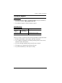
International http://support.aten.com
International 886-2-8692-6959
China 86-400-810-0-810
Japan 81-3-5615-5811
Korea 82-2-467-6789
North America 1-888-999-ATEN ext 4988
United Kingdom 44-8-4481-58923

VS0201 / VS0401 User Manual
iv
Package Contents
The VS0201 / VS0401 package consists of:
1 VS0201 / VS0401 2/4-Port VGA Switch with Audio
1 Power Adapter
1 User Instructions*
Check to make sure that all the components are present and that nothing got
damaged in shipping. If you encounter a problem, contact your dealer.
Read this manual thoroughly and follow the installation and operation
procedures carefully to prevent any damage to the unit, and/or any of the
devices connected to it.
* Features may have been added to the VS0201 / VS0401 since this manual
was published. Please visit our website to download the most up-to-date
version.
© Copyright 2017 ATEN® International Co., Ltd.
Man
ual Date: 2017-09-2
6
A
TEN and the ATEN logo are registered trademarks of ATEN International Co., Ltd. All rights reserved.
All other brand names and trademarks are the registered property of their respective owners.

VS0201 / VS0401 User Manual
v
Contents
FCC Information . . . . . . . . . . . . . . . . . . . . . . . . . . . . . . . . . . . . . . . . . . . . ii
RoHS . . . . . . . . . . . . . . . . . . . . . . . . . . . . . . . . . . . . . . . . . . . . . . . . . . . . . ii
SJ/T 11364-2006 . . . . . . . . . . . . . . . . . . . . . . . . . . . . . . . . . . . . . . . . . . . . ii
User Information . . . . . . . . . . . . . . . . . . . . . . . . . . . . . . . . . . . . . . . . . . . .iii
Online Registration . . . . . . . . . . . . . . . . . . . . . . . . . . . . . . . . . . . . . . . .iii
Telephone Support . . . . . . . . . . . . . . . . . . . . . . . . . . . . . . . . . . . . . . . .iii
User Notice . . . . . . . . . . . . . . . . . . . . . . . . . . . . . . . . . . . . . . . . . . . . .iii
Package Contents . . . . . . . . . . . . . . . . . . . . . . . . . . . . . . . . . . . . . . . . . . .iv
About this Manual . . . . . . . . . . . . . . . . . . . . . . . . . . . . . . . . . . . . . . . . . . vii
Conventions . . . . . . . . . . . . . . . . . . . . . . . . . . . . . . . . . . . . . . . . . . . . . . .viii
Product Information . . . . . . . . . . . . . . . . . . . . . . . . . . . . . . . . . . . . . . . . .viii
1. Introduction
Overview. . . . . . . . . . . . . . . . . . . . . . . . . . . . . . . . . . . . . . . . . . . . . . . . . . .1
Features . . . . . . . . . . . . . . . . . . . . . . . . . . . . . . . . . . . . . . . . . . . . . . . . . . . 2
Requirements . . . . . . . . . . . . . . . . . . . . . . . . . . . . . . . . . . . . . . . . . . . . . .3
Source Device. . . . . . . . . . . . . . . . . . . . . . . . . . . . . . . . . . . . . . . . . . . .3
Display Device . . . . . . . . . . . . . . . . . . . . . . . . . . . . . . . . . . . . . . . . . . .3
Cables. . . . . . . . . . . . . . . . . . . . . . . . . . . . . . . . . . . . . . . . . . . . . . . . . .3
Components . . . . . . . . . . . . . . . . . . . . . . . . . . . . . . . . . . . . . . . . . . . . . . . .4
VS0201 Front View . . . . . . . . . . . . . . . . . . . . . . . . . . . . . . . . . . . . . . . 4
VS0401 Front View. . . . . . . . . . . . . . . . . . . . . . . . . . . . . . . . . . . . . . . . 4
VS0201 Rear View . . . . . . . . . . . . . . . . . . . . . . . . . . . . . . . . . . . . . . . .5
VS0401 Rear View . . . . . . . . . . . . . . . . . . . . . . . . . . . . . . . . . . . . . . . .5
2. Hardware Setup
Installation. . . . . . . . . . . . . . . . . . . . . . . . . . . . . . . . . . . . . . . . . . . . . . . . . . 7
Installation Diagram . . . . . . . . . . . . . . . . . . . . . . . . . . . . . . . . . . . . . . .8
Installing the RS-232 Controller . . . . . . . . . . . . . . . . . . . . . . . . . . . . . .8
3. Operation
Overview. . . . . . . . . . . . . . . . . . . . . . . . . . . . . . . . . . . . . . . . . . . . . . . . . . .9
Manual Source Selection . . . . . . . . . . . . . . . . . . . . . . . . . . . . . . . . . . .9
Remote Control Source Selection. . . . . . . . . . . . . . . . . . . . . . . . . . . . .9
Pushbutton Lock . . . . . . . . . . . . . . . . . . . . . . . . . . . . . . . . . . . . . . . . .10
VS0201 . . . . . . . . . . . . . . . . . . . . . . . . . . . . . . . . . . . . . . . . . . . . .10
VS0401 . . . . . . . . . . . . . . . . . . . . . . . . . . . . . . . . . . . . . . . . . . . . .10
Powering Off and Restarting. . . . . . . . . . . . . . . . . . . . . . . . . . . . . . . .10
RS-232 Serial Interface . . . . . . . . . . . . . . . . . . . . . . . . . . . . . . . . . . . . . .11
Configuring the Serial Port . . . . . . . . . . . . . . . . . . . . . . . . . . . . . . . . .11
Verification . . . . . . . . . . . . . . . . . . . . . . . . . . . . . . . . . . . . . . . . . . . . . 11
Switch Port Command . . . . . . . . . . . . . . . . . . . . . . . . . . . . . . . . . . . . 12
Switch Mode Command . . . . . . . . . . . . . . . . . . . . . . . . . . . . . . . . . . . 13

VS0201 / VS0401 User Manual
vi
Echo Command. . . . . . . . . . . . . . . . . . . . . . . . . . . . . . . . . . . . . . . . . .15
Standby Command . . . . . . . . . . . . . . . . . . . . . . . . . . . . . . . . . . . . . . .16
Dynamic DDC Command . . . . . . . . . . . . . . . . . . . . . . . . . . . . . . . . . .17
Pushbutton Lock Command . . . . . . . . . . . . . . . . . . . . . . . . . . . . . . . .18
Read Firmware Command . . . . . . . . . . . . . . . . . . . . . . . . . . . . . . . . .19
Reset Command . . . . . . . . . . . . . . . . . . . . . . . . . . . . . . . . . . . . . . . . .20
Baud Rate Command . . . . . . . . . . . . . . . . . . . . . . . . . . . . . . . . . . . . .21
4. The Firmware Upgrade Utility
Introduction . . . . . . . . . . . . . . . . . . . . . . . . . . . . . . . . . . . . . . . . . . . . . . . .23
Downloading the Firmware Upgrade Package . . . . . . . . . . . . . . . . . .23
Preparation . . . . . . . . . . . . . . . . . . . . . . . . . . . . . . . . . . . . . . . . . . . . . . . .24
Starting the Upgrade . . . . . . . . . . . . . . . . . . . . . . . . . . . . . . . . . . . . . . . .25
Upgrade Succeeded . . . . . . . . . . . . . . . . . . . . . . . . . . . . . . . . . . . . . . . .27
Upgrade Failed . . . . . . . . . . . . . . . . . . . . . . . . . . . . . . . . . . . . . . . . . . . . .27
Firmware Upgrade Recovery . . . . . . . . . . . . . . . . . . . . . . . . . . . . . . . . . .28
Appendix
Safety Instructions. . . . . . . . . . . . . . . . . . . . . . . . . . . . . . . . . . . . . . . . . . .29
General . . . . . . . . . . . . . . . . . . . . . . . . . . . . . . . . . . . . . . . . . . . . . . . .29
Technical Support . . . . . . . . . . . . . . . . . . . . . . . . . . . . . . . . . . . . . . . . . .31
International . . . . . . . . . . . . . . . . . . . . . . . . . . . . . . . . . . . . . . . . . . . .31
North America . . . . . . . . . . . . . . . . . . . . . . . . . . . . . . . . . . . . . . . . . .31
Specifications . . . . . . . . . . . . . . . . . . . . . . . . . . . . . . . . . . . . . . . . . . . . . .32
Limited Warranty. . . . . . . . . . . . . . . . . . . . . . . . . . . . . . . . . . . . . . . . . . . .33

VS0201 / VS0401 User Manual
vii
About this Manual
This User Manual is provided to help you get the most from your system. It
covers all aspects of installation, configuration and operation. An overview of
the information found in the manual is provided below.
Chapter 1, Introduction, introduces you to the VS0201 / VS0401 system.
Its purpose, features and benefits are presented, and its front and back panel
components are described.
Chapter 2, Hardware Setup, describes how to set up your VS0201 /
VS0401 installation.
Chapter 3, Operation, explains the fundamental concepts involved in
operating the VS0201 / VS0401.
Chapter 4, The Firmware Upgrade Utility, explains how to download the
firmware upgrade utility and install updates on the VS0201 / VS0401.
An Appendix, provides specifications and other technical information
regarding the VS0201 / VS0401.

VS0201 / VS0401 User Manual
viii
Conventions
This manual uses the following conventions:
Product Information
For information about all ATEN products and how they can help you connect
without limits, visit ATEN on the Web or contact an ATEN Authorized
Reseller. Visit ATEN on the Web for a list of locations and telephone numbers:
Monospaced Indicates text that you should key in.
[ ] Indicates keys you should press. For example, [Enter] means to
press the Enter key. If keys need to be chorded, they appear
together in the same bracket with a plus sign between them:
[Ctrl+Alt].
1. Numbered lists represent procedures with sequential steps.
♦ Bullet lists provide information, but do not involve sequential steps.
→ Indicates selecting the option (on a menu or dialog box, for
example), that comes next. For example, Start
→ Run means to
open the Start menu, and then select Run.
Indicates critical information.
International http://www.aten.com
North America http://www.aten-usa.com

1
Chapter 1
Introduction
Overview
The VS0201 / VS0401 2/4-Port VGA Switch with Audio allows you to connect
two/four source computers to a single monitor or projector with full audio and
quickly switch between the devices for use.
The convenient front panel pushbuttons and IR remote control allow you to
easily toggle between VGA/Audio sources, while front panel LEDs indicate
the connected source device at a glance. In addition, with support for up to 300
MHz bandwidth, the VS0201 / VS0401 allows for the transmission of large
amounts of display information at very high speeds for a clear professional
appearance.
Furthermore, for complete systems integration, serial control is standard
through the VS0201 / VS0401’s built-in RS-232 ports, which allow the switch
to be controlled through a high-end controller or PC.
The ability to use high-end serial control devices to initiate RS-232 commands
allows the VS0201 / VS0401 to be controlled by a secondary system to utilize
advanced switch functions such as port switching, auto switching, and front
panel pushbutton lock.
The VS0201 / VS0401 is perfect for the meeting room, media centers, class
rooms, or any presentation environment requiring multiple audio/video sources
to be accessed on a single display.

Chapter 1. Introduction
2
Features
Displays the video output of two (VS0201) or four (VS0401) computers on
a single monitor or projector
Quick and easy switching between VGA/Audio sources via front panel
pushbuttons, RS-232, or IR remote control
Superior video quality – up to 1920 x 1440
Long-distance transmission – up to 65 m
Supports– VGA, SVGA, UXGA, WUXGA, and multisync monitors
Video DynaSync™ - Exclusive ATEN technology eliminates boot-up
display problems and optimizes resolution when switching between ports
Built-in bi-directional RS-232 serial port for high-end system control, and
advanced RS-232 functions*
RS-232 Functions:
Auto Switching – sets the priority for auto switching to a connected
port
Pushbutton Lock – locks use of the front panel pushbuttons
Supports stereo audio
Dynamic DDC compatible
Supports up to 300 MHz bandwidth for optimal video quality
LED indication of power status and source device
All-metal casing provides durability and protection
Plug-and-play – no software installation required
Note: The VS0201 / VS0401 RS-232 AP and GUI instructions can be
downloaded from the ATEN website: www.aten.com.

VS0201 / VS0401 User Manual
3
Requirements
Source Device
The following equipment must be installed on the source device or computer
that acts as a source of VGA/Audio content:
VGA video card with HDB-15 connector
Audio source with stereo output
Display Device
A VGA, SVGA, UXGA, WUXGA or multisync monitor or multimedia
projector with an HDB-15 connector
Stereo and/or balanced audio speakers
Cables
1 VGA/Audio cable for each source device you will be connecting
1 VGA/Audio cable for your display device

Chapter 1. Introduction
4
Components
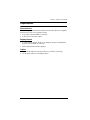
VS0201 Front View
VS0401 Front View
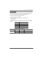
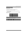
No. Component Function
1Port Selection
Pushbuttons
Pressing a port selection pushbutton routes the
VGA/Audio source from the corresponding input
port to the output port for display.
2 Port LEDs There is one port LED next to each port selection
pushbutton. This lights green to indicate that the
corresponding port has been selected.
The connected port LED will flash when the front
panel pushbuttons are manually locked.
3 Power Pushbutton Push this button to turn on / off the switch.
4 Power LED
The LED (green) lights up when the switch is
powered on.
The LED (orange) lights up to indicate that the
switch is in standby mode.
1
2
4
3
4
3
1
2

VS0201 / VS0401 User Manual
5
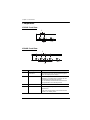
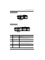
VS0201 Rear View
VS0401 Rear View
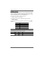
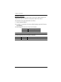
No. Component Function
1 Grounding Terminal The grounding wire used to ground the unit
attaches here.
2 RS-232 Serial Port This is the serial remote port for input source
selection and high-end system control.
3 External IR Receiver
Port
Connect the IR Receiver to this port.
4 Video / Audio Input Each input section is comprised of a VGA
connector and a mini stereo audio jack. The cables
that connect to the video and audio output ports on
the computers/source devices plug in here.
5 Power Jack The power adapter cable plugs in here.
6 Video / Audio Output The cables that connect to the video and audio
ports for the video display and audio output plug in
here.
2
4
3
1
5
6
2
4
3
1
5
6

Chapter 1. Introduction
6
This Page Is Intentionally Left Blank

7
Chapter 2
Hardware Setup
Installation
Installation of the VS0201 / VS0401 is simply a matter of plugging in the
appropriate cables.
To install the switch, refer to the installation diagram on page 8 as you perform
the following steps:
1. Use a VGA/Audio cable to connect the VGA/Audio input of the video
display and speaker devices to the VGA/Audio output ports on the rear of
the VS0201 / VS0401.
2. Use VGA/Audio cables to connect the VGA/Audio output ports on the
source device(s) to the VGA/Audio input ports on the VS0201 / VS0401.
Two/Four VGA/Audio input ports are located on the rear of the switch.
3. Use a grounding wire to ground the unit by connecting one end of the wire
to the grounding terminal, and the other end of the wire to a suitable
grounded object.
4. Plug the provided power adapter into an appropriate AC power source;
plug the power adapter cable into the power jack on the VS0201 / VS0401.
5. (Optional) To control the VS0201 / VS0401 system through the RS-232
port, connect the hardware/software controller here.
6. (Optional) Connect the IR Receiver into the External IR Receiver Input
Port.
The installation is complete, you may power on the display and source devices.
1. Important safety information regarding the placement of this
device is provided on page 29. Please review it before
proceeding.
2. Make sure that the power to all devices connected to the
installation are turned off. You must unplug the power cords of
any computers that have the Keyboard Power On function.

Chapter 2. Hardware Setup
8
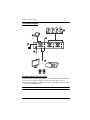
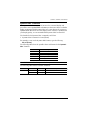
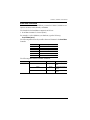
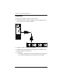
Installation Diagram
Installing the RS-232 Controller
In order to use the RS-232 serial interface to attach a high-end controller (such
as a PC) to the VS0201 / VS0401, use a RS-232 serial cable. The end
connecting to the VS0201 / VS0401 should have a 9-pin male connector. Refer
to step 5 on the diagram above.
Note: To configure the RS-232 serial port see page 11.
4
6
2
1
OR
5
3

9
Chapter 3
Operation
Overview
The VS0201 / VS0401 2/4-Port VGA Switch with Audio offers easy source
device selection with either the front panel pushbuttons, IR remote control, or
RS-232 serial interface. This chapter describes Source Selection, Power on
Detection mode, Pushbutton Lock, Powering Off/Restarting, and the RS-232
serial port configuration and commands.
Note: Whenever the VS0201 / VS0401 is powered on, it automatically
remembers the last connected port being used and connects to it.You
may choose one of the methods outlined below to select a different port.
Manual Source Selection
To select the source device to view on your VGA display, press the front panel
pushbutton that corresponds to the port it is connected to.
Note: The Port LED (green) light indicates which port is currently selected.
Remote Control Source Selection
First plug the External IR Receiver into the rear of the VS0201 / VS0401, place
the receiver where the IR signal can be reached, and aim the remote at the
External IR receiver.
To select a source device with the remote control, press the number button that
corresponds to the port it is connected to, or cycle through the source devices
by pushing the Port Up and Port Down buttons on the remote control unit, as
such:
Use the Port Up button to select the next port in ascending order (from left
to right on the front view panel).
Use the Port Down button to select the previous port in descending order
(from right to left on the front view panel).

Chapter 3. Operation
10
Pushbutton Lock
Pushbutton Lock allows you to secure your device by locking use of the front
panel pushbuttons. To lock/unlock the front panel pushbuttons, do the
following:
VS0201
Press and hold both 1 and 2 port selection pushbuttons for 5 seconds, then
release.
VS0401
Press and hold both 1 and 4 port selection pushbuttons for 5 seconds, then
release.
Note: 1. The front panel port LED will flash at one second intervals to indicate
the pushbutton lock feature is enabled.
2. Repeat the steps above to unlock the front panel pushbuttons.
Powering Off and Restarting
If you power off the VS0201 / VS0401, follow these steps before powering it
on again:
1. Power off the attached devices.
2. Unplug the power adapter cable from the VS0201 / VS0401.
3. Wait 10 seconds, and then plug the power adapter cable back in.
4. After the VS0201 / VS0401 is powered on, power on the attached devices.

VS0201 / VS0401 User Manual
11
RS-232 Serial Interface
The VS0201 / VS0401’s built-in bi-directional RS-232 serial interface allows
system control through a high-end controller, PC, and/or home automation /
home theater software package.
Configuring the Serial Port
The controller’s serial port should be configured as follows:
The RS-232 control commands for Switch Port, Auto Switch, Power on
Detection, Dynamic DDC, Pushbutton Lock, Read Firmware and Reset are
found on the pages that follow.
Verification
In the steps below, after entering a command, a verification message appears
at the end of the command line as follows:
Command OK - indicates that the command is correct and successfully
performed by the switch
Command incorrect - indicates that the command has the wrong format
and/or values.
Baud Rate 19200
Data Bits 8
Parity None
Stop Bits 1
Flow Control None

Chapter 3. Operation
12
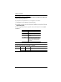
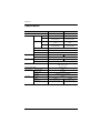
Switch Port Command
The formulas for Switch Port commands are as follows:
1. Switch Command + Input Command + Port Number [Enter]
For example, to switch the input port to port 02, type the following:
sw i02 [Enter]
2. Switch Command + Control [Enter]
For example, to switch to the next port, type the following:
sw + [Enter]
The following tables show the possible values and formats for the Switch Port
formulas:
Note: 1. Each command string can be separated with a space.
2. If the Port Number string is skipped, the default value is used.
The following table shows the available list of commands:
Command Description
sw Switch command
Input Command Description
i Input command
Port number Description
xx 01-04 port (default is 01)
Control Description
+ Switch to next port
- Switch to previous port
Command Input Port Control Enter Description
sw i xx [Enter] Switch to input port xx
+ [Enter] Switch to the next input
- [Enter] Switch to the previous input
Page is loading ...
Page is loading ...
Page is loading ...
Page is loading ...
Page is loading ...
Page is loading ...
Page is loading ...
Page is loading ...
Page is loading ...
Page is loading ...
Page is loading ...
Page is loading ...
Page is loading ...
Page is loading ...
Page is loading ...
Page is loading ...
Page is loading ...
Page is loading ...
Page is loading ...
Page is loading ...
Page is loading ...
Page is loading ...
-
 1
1
-
 2
2
-
 3
3
-
 4
4
-
 5
5
-
 6
6
-
 7
7
-
 8
8
-
 9
9
-
 10
10
-
 11
11
-
 12
12
-
 13
13
-
 14
14
-
 15
15
-
 16
16
-
 17
17
-
 18
18
-
 19
19
-
 20
20
-
 21
21
-
 22
22
-
 23
23
-
 24
24
-
 25
25
-
 26
26
-
 27
27
-
 28
28
-
 29
29
-
 30
30
-
 31
31
-
 32
32
-
 33
33
-
 34
34
-
 35
35
-
 36
36
-
 37
37
-
 38
38
-
 39
39
-
 40
40
-
 41
41
-
 42
42


