14 • FLECK 7000SXT Service Manual
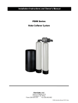
VALVE ASSEMBLY
Item No. QTY Part No. Description
1 .................... 1 .......... 61050 .......................Valve Body Assembly, 7000, 32 mm Dist
2 .................... 1 .......... 61452-10 ..................Piston Assembly, 7000, Softener, D/F 35 gpm
........... 61453-10 ..................Piston Assembly, 7000, Softener, D/F 28 gpm
........... 61452-20 ..................Piston Assembly, 7000, Filter 35 gpm
3 .................... 3 .......... 40576 .......................Clip, H, Plastic, 7000 (see NOTE above)
4 .................... 1 .......... 61438 .......................Seal & Spacer Kit, 7000, D/F
5 .................... 1 .......... 60016-01 ..................Brine Valve Assembly, 7000, 560CD
6 .................... 1 .......... 40577 .......................Turbine Meter Assembly, 7000
7 ................................. 61454-000 ................ Injector Assembly, 7000, #000 Injector -
Brown
........... 61454-00 ..................Injector Assembly, 7000, #00 Injector - Violet
........... 61454-0 ....................Injector Assembly, 7000, #0 Injector - Red
........... 61454-1 ....................Injector Assembly, 7000, #1 Injector - White
........... 61454-2 ....................Injector Assembly, 7000, #2 Injector - Blue
........... 61454-3 ....................Injector Assembly, 7000, #3 Injector - Yellow
........... 61454-4 ....................Injector Assembly, 7000, #4 Injector - Green
........... 61454-5 ....................Injector Assembly, 7000, #5 Injector - Gray
8 .................... 1 .......... 40556 .......................Cap, Injector
9 ................................. 61450-00 .................. BLFC 3/8", Blank
........... 61450-12 ..................BLFC 3/8", 0.125 gpm
........... 61450-25 ..................BLFC 3/8", 0.25 gpm
........... 61450-50 ..................BLFC 3/8", 0.50 gpm
........... 61450-100 ................BLFC 3/8", 1.0 gpm
........... 61451-00 ..................BLFC 1/2", Blank
........... 61451-12 ..................BLFC 1/2", 0.125 gpm
........... 61451-25 ..................BLFC 1/2", 0.25 gpm
........... 61451-50 ..................BLFC 1/2", 0.50 gpm
........... 61451-100 ................BLFC 1/2", 1.0 gpm
10 ............................... 61455-00 .................. DLFC 3/4", Blank
........... 61455-17 ..................DLFC 3/4", 1.7 gpm
........... 61455-20 ..................DLFC 3/4", 2.0 gpm
........... 61455-24 ..................DLFC 3/4", 2.4 gpm
........... 61455-30 ..................DLFC 3/4", 3.0 gpm
........... 61455-35 ..................DLFC 3/4", 3.5 gpm
........... 61455-40 ..................DLFC 3/4", 4.0 gpm
........... 61455-45 ..................DLFC 3/4", 4.5 gpm
........... 61455-50 ..................DLFC 3/4", 5.0 gpm
........... 61455-60 ..................DLFC 3/4", 6.0 gpm
........... 61455-70 ..................DLFC 3/4", 7.0 gpm
........... 61456-00 ..................DLFC 1", Blank
........... 61456-8.0 .................DLFC 1", 8.0 gpm
........... 61456-9.0 .................DLFC 1", 9.0 gpm
........... 61456-10 ..................DLFC 1", 10.0 gpm
........... 61456-12 ..................DLFC 1", 12.0 gpm
........... 61456-15 ..................DLFC 1", 15.0 gpm
........... 61456-20 ..................DLFC 1", 20.0 gpm
........... 61456-25 ..................DLFC 1", 25.0 gpm
........... 61456-30 ..................DLFC 1", 30.0 gpm
11 .................. 1 .......... 43376 .......................O-ring, -021, 7000, CSTM
12 .................. 2 .......... 13302-01 ..................O-ring, -014, 560CD
13 .................. 1 .......... 40946 .......................Clip, Brine Retaining
14 .................. 1 .......... 40945 .......................Clip, Drain Retaining
15 .................. 1 .......... 40950 .......................Screen, Injector, 7000
16 .................. 1 .......... 40951 .......................O-ring, -220
17 .................. 1 .......... 18280 .......................Collector, Top, 1" x .011, Gray
18 .................. 1 .......... 61419 .......................Kit, 1.05" Distributor, Adapter
19 .................. 1 .......... 19054 .......................O-ring, -124
20 .................. 1 .......... 40538 .......................Retainer, 32 mm, O-ring Dist, 7000
23 .................. 1 .......... 61XXX .......................DLFC Kits
24 .................. 1 .......... 13363 .......................Washer, Plain, .145 ID SS
25 .................. 1 .......... 13296 .......................Screw, Hex, Washer, 6-20 x 1/2
Not Shown:
........... 18569 .......................Retainer Tank Seal
........... 40677 .......................Tube, Distributor, 32 mm
........... 40924 .......................Distributor, 32 mm
........... 40697-02 ..................Collector, 32 mm Bayonet
........... 12763-10 ..................Stuffer Tool Assy, 7000
........... 18303 .......................O-ring, -336, Top of Tank
Filter Valves:
........... 40947-01 ..................Plug, Brine Valve, w/O-ring
........... 40990-01 ..................Plug, Injector, w/O-ring
Item No. QTY Part No. Description
61500-7000EXP Rev C
* See NOTE
NOTE: Installers are responsible for
securing the plastic H Clips (p/n
40576 red clips) when attaching
connectors. The red clips will
break if you attempt to force into
position without fully inserting
the connector into the body. If the
connector is inserted properly
the red clip insertion path will be
clear.