Page is loading ...

Dell™XPS™210ServiceManual
Before You Begin
About Your Computer
Technical Overview
Specifications
Troubleshooting
System Setup
Removing the Computer Cover
Removing and Installing Parts
Replacing the Computer Cover
Notes, Notices, and Cautions
Information in this document is subject to change without notice.
©2006DellInc.Allrightsreserved.
Reproduction in any manner whatsoever without the written permission of Dell Inc. is strictly forbidden.
Trademarks used in this text: Dell, the DELL logo, and Dimension are trademarks of Dell Inc.; Intel, Pentium, Intel SpeedStep, and Celeron are registered trademarks of Intel
Corporation; Microsoft and Windows are registered trademarks of Microsoft Corporation.
Other trademarks and trade names may be used in this document to refer to either the entities claiming the marks and names or their products. Dell Inc. disclaims any
proprietary interest in trademarks and trade names other than its own.
August 2006 Rev. A00
NOTE: A NOTE indicates important information that helps you make better use of your computer.
NOTICE: A NOTICE indicates either potential damage to hardware or loss of data and tells you how to avoid the problem.
CAUTION: A CAUTION indicates a potential for property damage, personal injury, or death.

Back to Contents Page
About Your Computer
Dell™XPS™210ServiceManual
Front View
Back View
Front View
--
NOTE: The front panel door does not close when you are using certain Flash Media, IEEE 1394, USB, or headphone connectors.
1
CD/DVD drive
eject button
Press this button to eject a CD/DVD from the drive.
2
CD/DVD drive
activity light
The drive activity light is on when the computer reads data from the
CD or DVD drive.
3
USB 2.0
connectors (2)
Use the front USB connectors for devices that you connect
occasionally, such as joysticks or cameras (see System Setup for more
information on booting to a USB device).
It is recommended that you use the back USB connectors for devices
that typically remain connected, such as printers and keyboards.
4
IEEE 1394
connector
Attach high-speed serial multimedia devices, such as digital video
cameras.
It is recommended that you use the back IEEE 1394 connector for
devices that typically remain connected, such as external hard drives
and other storage devices.
5
vents
For adequate cooling, do not block any of the vents.
NOTICE: Ensure that there is a minimum of two inches of space
between all vents and any object near the vents.
NOTICE: Do not lift or carry the computer by the vents to avoid
damage to the computer.
NOTICE: Keep the vent area clean and dust free to ensure that the
computer is adequately ventilated. Use only a dry cloth to clean the
vent area to avoid water damage to the computer.
6
power button
Press this button to turn on the computer.

Back View
Back Panel Connectors
NOTICE: To avoid losing data, do not use the power button to turn
off the computer. Instead, perform an operating system shutdown.
7
power light
The power light illuminates and indicates different power states:
¡ No light — The computer is turned off.
¡ Steady green — The computer is in a normal operating
state.
¡ Blinking green — The computer is in a power-saving
state.
¡ Blinking or solid amber — See Power Problems in your
computer Owner's Manual.
8
front panel door
release button
Press this button to access the front panel connectors.
9
microphone
connector
Use the pink microphone connector to attach a personal computer
microphone for voice or musical input into a sound or telephony
program.
On computers with a sound card, use the microphone connector on
the card.
10
headphone
connector
Use the green headphone connector to attach headphones and most
kinds of speakers.
11
FlexBay
Use the Flexbay for an optional floppy drive or Media Card Reader.
12
hard drive
activity light
The hard drive activity light is on when the computer reads data from,
or writes data to the hard drive. The light might also be on when a
device such as a CD player is operating.
13
diagnostic lights
For an explanation of the diagnostic light codes, see Diagnostic
Lights.
14
front panel door
This panel covers the CD/DVD drive, the Media Card Reader, and the
optional floppy drive.
1
voltage selection switch (may not be
available on all computers)
See the safety instructions in the Product
Information Guide for more information.
2
power connector
Insert the power cable.
3
back panel connectors
Plug IEEE 1394, USB and other devices into the
appropriate connector.
4
card slots
Access connectors for any installed PCI Express
cards.

Back to Contents Page
1
link integrity
light
l Green — A good connection exists between a 10-Mbps network
and the computer.
l Orange — A good connection exists between a 100-Mbps
network and the computer.
l Off — The computer is not detecting a physical connection to the
network.
2
network
adapter
connector
To attach your computer to a network or broadband device, connect one
end of a network cable to either a network jack or your network or
broadband device. Connect the other end of the network cable to the
network adapter connector on the back panel of your computer. A click
indicates that the network cable has been securely attached.
NOTE: Do not plug a telephone cable into the network connector.
On computers with a network connector card, use the connector on the
card.
It is recommended that you use Category 5 wiring and connectors for
your network. If you must use Category 3 wiring, force the network
speed to 10 Mbps to ensure reliable operation.
3
network
activity light
Flashes a yellow light when the computer is transmitting or receiving
network data. A high volume of network traffic may make this light
appear to be in a steady "on" state.
4
modem
connector
Use the modem connector to connect your computer to the Internet.
5
rear surround
sound
connector
Use the black surround sound connector to attach multichannel-capable
speakers.
6
line-in
connector
Use the blue line-in connector to attach a record/playback device such
as a cassette player, CD player, or VCR.
On computers with a sound card, use the connector on the card.
7
line-out
connector
Use the green line-out connector to attach headphones and most
speakers with integrated amplifiers.
On computers with a sound card, use the connector on the card.
8
microphone
Use the pink connector to attach a personal computer microphone for
voice or musical input into a sound or telephony program.
On computers with a sound card, use the microphone connector on the
card.
9
side surround
sound
connector
Use the grey surround sound connector to attach multichannel-capable
speakers.
10
center/LFE
connector
The LFE (Low Frequency Effects) Audio channel, found in digital surround
sound audio schemes, carries only low frequency information of 80 Hz
and below. The LFE channel drives a subwoofer to provide extremely
low bass extension. Systems not using subwoofers can shunt the LFE
information to the main speakers in the surround sound setup.
11
S/PDIF
connector
This connector is used to transmit digital audio without going through
an analog audio conversion process.
12
VGA connector
If your monitor has a VGA connector, plug it into the VGA connector on
the computer.
13
USB 2.0
connectors (6)
Use the back USB connectors for devices that typically remain
connected, such as printers and keyboards.
It is recommended that you use the front USB connectors for devices
that you connect occasionally, such as joysticks or cameras.
14
IEEE 1394
connector
Attach high-speed serial multimedia devices, such as digital video
cameras.

Back to Contents Page
Before You Begin
Dell™XPS™210ServiceManual
Getting Started
Recommended Tools
Turning Off Your Computer
Before Working Inside Your Computer
Getting Started
This manual provides procedures for removing and replacing the components in your computer. Unless otherwise noted, each procedure assumes that the
following conditions exist:
l You have performed the steps in Turning Off Your Computer and Before Working Inside Your Computer.
l YouhavereadthesafetyinformationinyourDell™Product Information Guide.
l A component can be replaced by performing the removal procedure in reverse order.
Recommended Tools
The procedures in this document may require the following tools:
l Small flat-blade screwdriver
l Phillips #0, #1, or #2 screwdriver
l Flash BIOS update program (download from support.dell.com)
Turning Off Your Computer
1. Shut down the operating system:
a. Save and close any open files, exit any open programs, click the Start button, and then click Shutdown.
b. In the Shut Down Windows window, select Shut Down.
The computer turns off after the operating system shutdown process finishes.
2. Ensure that the computer and any attached devices are turned off. If your computer and attached devices did not automatically turn off when you shut
down your operating system, press and hold the power button for 4 seconds.
Before Working Inside Your Computer
Use the following safety guidelines to help protect your computer from potential damage and to help ensure your own personal safety.
1. Follow the steps in Turning Off Your Computer.
NOTICE: To avoid losing data, save and close any open files and exit any open programs before you turn off your computer.
CAUTION: Before you begin any of the procedures in this section, follow the safety instructions in the ProductInformationGuide.
CAUTION: Handle components and cards with care. Do not touch the components or contacts on a card. Hold a card by its edges or by its metal
mounting bracket. Hold a component such as a processor by its edges, not by its pins.
NOTICE: Only a certified service technician should perform repairs on your computer. Damage due to servicing that is not authorized by Dell is not
covered by your warranty.
NOTICE: When you disconnect a cable, pull on its connector or on its strain-relief loop, not on the cable itself. Some cables have a connector with
locking tabs; if you are disconnecting this type of cable, press in on the locking tabs before you disconnect the cable. As you pull connectors apart, keep
them evenly aligned to avoid bending any connector pins. Also, before you connect a cable, ensure that both connectors are correctly oriented and
aligned.
NOTICE: To avoid damaging the computer, perform the following steps before you begin working inside the computer.

2. Disconnect any telephone or network cables from the computer.
3. Disconnect your computer and all attached devices from their electrical outlets, and then press the power button to ground the system board.
4. Remove the computer cover (see Removing the Computer Cover).
Back to Contents Page
NOTICE: To disconnect a network cable, first unplug the cable from your computer and then unplug it from the network port or device.
CAUTION: To guard against electrical shock, always unplug your computer from the electrical outlet before opening the cover.
NOTICE: Before touching anything inside your computer, ground yourself by touching an unpainted metal surface, such as the metal at the back of the
computer. While you work, periodically touch an unpainted metal surface to dissipate any static electricity that could harm internal components.

Back to Contents Page
Replacing the Computer Cover
Dell™XPS™210ServiceManual
1. Ensure that all cables are connected and folded out of the way.
Gently pull the power cables toward you so that they do not get caught underneath the drives.
2. Ensure that no tools or extra parts are left inside the computer.
3. Install the cover:
a. Align the bottom of the cover with the tabs located along the bottom of edge of the computer.
b. Using the tabs as leverage, rotate the cover downward.
c. Press down on the right side of the cover until it closes.
d. Press down on the left side of the cover until it closes.
e. Ensure that both sides of the cover are locked before moving the computer to the upright position.
4. Connect your computer and devices to electrical outlets, and then turn them on.
Back to Contents Page
CAUTION: Before you begin any of the procedures in this section, follow the safety instructions in the Product Information Guide.
NOTICE: To connect a network cable, first plug the cable into the network port or device, and then plug it into the computer.

Back to Contents Page
Removing the Computer Cover
Dell™XPS™210ServiceManual
1. Follow the procedures in Before You Begin.
2. Lay your computer on its side with the computer cover facing up.
3. Pull back the cover release latch on the top panel.
4. Locate the three hinge tabs on the bottom edge of the computer.
5. Grip the sides of the computer cover and pivot the cover up, using the bottom hinges as leverage points.
6. Lift the cover away and set it aside in a secure location.
Back to Contents Page
CAUTION: Before you begin any of the procedures in this section, follow the safety instructions in the Product Information Guide.
CAUTION: To guard against electrical shock, always unplug your computer from the electrical outlet before opening the cover.
NOTICE: Before touching anything inside your computer, ground yourself by touching an unpainted metal surface, such as the metal at the back of the
computer. While you work, periodically touch an unpainted metal surface to dissipate any static electricity that could harm internal components.
NOTICE: Ensure that sufficient space exists to support the removed cover—at least 30 cm (1 ft) of desktop space.
NOTICE: Ensure that you are working on a level, protected surface to avoid scratching either the computer or the surface on which it is resting.
1
computer cover
2
cover release latch
3
security cable slot

Back to Contents Page
Removing and Installing Parts
Dell™XPS™210ServiceManual
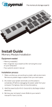
Memory
You can increase your computer memory by installing memory modules on the system board.
Your computer supports unbuffered, non-ECC, DDR2 memory.
DDR2 Memory Overview
DDR2 memory modules should be installed in pairs of matched memory size, speed, and technology. If the DDR2 memory modules are not installed in matched
pairs, the computer will continue to operate, but with a slight reduction in performance. See the label on the module to determine the module capacity.
The recommended memory configurations are:
l A pair of matched memory modules installed in DIMM connectors 1 and 2 (white securing clips)
or
l A pair of matched memory modules installed in DIMM connectors 1 and 2 and another matched pair installed in DIMM connectors 3 and 4 (black securing
clips)
l If you install mixed pairs of DDR2 800-MHz (PC2-6400) and DDR2 533-MHz (PC2-4300) memory, the modules function at the speed of the slowest
module installed.
l Be sure to install a single memory module in DIMM connector 1, the connector closest to the processor, before you install modules in the other
connectors.
Memory
Cards
Hard Drive
CD/DVD Drive
Floppy Drive (Optional)
Media Card Reader (Optional)
Heat Sink Assembly
Fan Assembly
Processor
Modem
Power Supply
System Board
Front I/O Panel
Battery
Front Panel
NOTE: Buffered memory is not supported on this computer.
NOTE: Always install DDR2 memory modules in the order indicated on the system board.
NOTICE: Do not install ECC memory modules.
1
matched pair of memory modules in DIMM connectors 1 and 2 (white securing clips)

Addressing Memory With 4-GB Configurations
Your computer supports a maximum of 4 GB of memory when you use two 2-GB DIMMs. Current operating systems, such as Microsoft®Windows®XP, can use
a maximum of 4 GB of address space; however, the amount of memory available to the operating system is less than 4 GB. Certain components within the
computer require address space in the 4-GB range. Any address space reserved for these components cannot be used by computer memory.
Installing Memory
1. Follow the procedures in Before You Begin.
2. Press out the securing clip at each end of the memory module connector.
3. Align the notch on the bottom of the module with the crossbar in the connector.
4. Insert the module into the connector until the module snaps into position.
If you insert the module correctly, the securing clips snap into the cutouts at each end of the module.
2
matched pair of memory modules in DIMM connectors 3 and 4 (black securing clips)
NOTICE: If you remove your original memory modules from the computer during a memory upgrade, keep them separate from any new modules that
you may have, even if you purchased the new modules from Dell. If possible, do not pair an original memory module with a new memory module.
Otherwise, your computer may not start properly. You should install your original memory modules in pairs either in DIMM connectors 1 and 2 or DIMM
connectors 3 and 4.
NOTE: Memory purchased from Dell is covered under your computer warranty.
CAUTION: Before you begin any of the procedures in this section, follow the safety instructions in the Product Information Guide.
NOTICE: To prevent static damage to components inside your computer, discharge static electricity from your body before you touch any of your
computer's electronic components. You can do so by touching an unpainted metal surface on the computer chassis.
1
memory connector closest to processor
2
securing clips (2)
3
connector
1
notch
2
crossbar
3
memory module
4
cutouts (2)
NOTICE: To avoid damage to the memory module, press the module straight down into the connector while you apply equal force to each end of the
module.

5. Replace the computer cover (see Replacing the Computer Cover).
6. Connect your computer and devices to electrical outlets, and then turn them on.
7. When a message appears stating that memory size has changed, press <F1> to continue.
8. Log on to your computer.
9. Right-click the My Computer icon, then click Properties.
10. Click the General tab.
11. To verify that the memory is installed correctly, check the amount of memory (RAM) listed.
Removing Memory
1. Follow the procedures in Before You Begin.
2. Press out the securing clip at each end of the memory module connector.
3. Grasp the module and pull up.
If the module is difficult to remove, ease the module back and forth to remove it from the connector.
Cards
YourDell™computerprovidesthefollowingslotsforPCIExpresscards:
l One PCI Express x16 card slot
l One PCI Express x1 card slot
NOTICE: To connect a network cable, first plug the cable into the network port or device and then plug it into the computer.
CAUTION: Before you begin any of the procedures in this section, follow the safety instructions in the Product Information Guide.
NOTICE: To prevent static damage to components inside your computer, discharge static electricity from your body before you touch any of your
computer's electronic components. You can do so by touching an unpainted metal surface on the computer chassis.
NOTE: The slots for the PCI Express x16 and PCI Express x1 cards are half-height slots.

If you are installing or replacing a PCI Express card, follow the procedures in the next section. If you are removing but not replacing a card, see Removing a
PCI Express Card.
If you are replacing a card, remove the current driver for the card from the operating system.
Installing a PCI Express Card
1. Follow the procedures in Before You Begin.
2. Gently push the release tab on the card retention door from the inside to pivot the door open. Because the door is attached, it will remain in the open
position.
3. If you are installing a new card, remove the filler bracket to create a card-slot opening, then continue with step 5.
4. If you are replacing a card that is already installed in the computer, grasp the card by its top corners, and ease it out of its connector.
If necessary, disconnect any cables connected to the card.
5. Prepare the card for installation.
See the documentation that came with the card for information on configuring the card, making internal connections, or otherwise customizing it for your
computer.
6. If you are installing the card into the x16 card connector, position the card so the securing slot is aligned with the securing tab, and then gently pull the
securing tab.
1
PCI Express x16 card
2
PCI Express x1 card
3
PCI Express x1 card slot
4
PCI Express x16 card slot
1
retention arm tab
2
PCI Express card
3
edge connector
4
card connector
5
securing tab
6
securing slot
CAUTION: Some network adapters automatically start the computer when they are connected to a network. To guard against electrical shock, be
sure to unplug your computer from its electrical outlet before installing any cards.

7. Place the card in the connector and press down firmly. Ensure that the card is fully seated in the slot.
8. Before you close the card retention door, ensure that:
l The tops of all cards and filler brackets are flush with the alignment bar.
l The notch in the top of the card or filler bracket fits around the alignment guide.
9. Close the card retention door by snapping it into place to secure the cards.
10. Connect any cables that should be attached to the card.
See the documentation that came with the card for information about the card cable connections.
11. Replace the computer cover (see Replacing the Computer Cover).
12. Connect the computer and devices to electrical outlets, and then turn them on.
13. Install any drivers required for the card as described in the card documentation.
1
card not fully seated
2
bracket within slot
3
bracket caught outside of slot
4
card fully seated
1
retention arm
2
PCI Express card
3
edge connector
4
card connector
NOTICE: Do not route card cables over or behind the cards. Cables routed over the cards can prevent the computer cover from closing properly or
cause damage to the equipment.
NOTICE: To connect a network cable, first plug the cable into the network port or device and then plug it into the computer.

Removing a PCI Express Card
1. Follow the procedures in Before You Begin.
2. Gently push the release tab on the card retention door from the inside to pivot the door open. Because the door is attached, it will remain in the open
position.
3. Gently pull back the securing tab, grasp the card by its top corners, and then ease it out of its connector.
If necessary, disconnect any cables connected to the card.
4. If you are removing the card permanently, install a filler bracket in the empty card-slot opening.
If you need a filler bracket, contact Dell.
5. Before you close the card retention door, ensure that:
l The tops of all cards and filler brackets are flush with the alignment bar.
l The notch in the top of the card or filler bracket fits around the alignment guide.
6. Close the card retention door by snapping it into place to secure the cards.
7. Replace the computer cover (see Replacing the Computer Cover).
8. Connect the computer and devices to electrical outlets, and then turn them on.
9. Uninstall the driver for that card.
Hard Drive
Removing a Hard Drive
1. Follow the procedures in Before You Begin.
2. Press in on the blue tabs on each side of the drive, then slide the drive up and out of the computer.
NOTE: Installing filler brackets over empty card-slot openings is necessary to maintain FCC certification of the computer. Filler brackets also keep
dust and dirt out of your computer.
CAUTION: Before you begin any of the procedures in this section, follow the safety instructions in the Product Information Guide.
CAUTION: To guard against electrical shock, always unplug your computer from the electrical outlet before removing the cover.
NOTICE: To avoid damage to the drive, do not set it on a hard surface. Instead, set the drive on a surface, such as a foam pad, that will sufficiently
cushion it.
NOTICE: If you are replacing a hard drive that contains data you want to keep, back up your files before you begin this procedure.
1
tabs (2)
2
hard drive

3. Lift the drive out of the computer and disconnect the power and hard-drive cables from the drive.
Installing a Hard Drive
1. Follow the procedures in Before You Begin.
2. Remove the old hard drive, as needed (see Removing a Hard Drive).
3. Unpack the hard drive, and prepare it for installation.
4. Check the documentation for the drive to verify that it is configured for your computer.
5. Connect the power cable and hard drive or SATA cable to the drive.
NOTICE: Do not pull the drive out of the computer by the drive cables. Doing so may cause damage to the cables and cable connectors.
1
power cable
2
hard drive cable or serial ATA data cable
NOTE: If your replacement hard drive does not have the plastic guide bracket attached, remove the bracket from the old drive by unsnapping it from the
drive. Snap the bracket onto the new drive.
1
tabs (2)
2
drive
3
drive screw holes
4
drive bracket

6. Check all connectors to be certain that they are properly cabled and firmly seated.
7. Gently slide the drive into the open bay until the hard drive plastic latch attaches to the hard drive holder on the chassis.
8. Align the drive screw holes with the screws projecting upwards on the heat sink holder.
9. Firmly press on the blue tab on each side of the drive until you hear a click.
10. Replace the computer cover (see Replacing the Computer Cover).
11. Connect your computer and devices to electrical outlets, and then turn them on.
See the documentation that came with the drive for instructions on installing any software required for drive operation.
CD/DVD Drive
Removing a CD/DVD Drive
1
power cable
2
hard drive plastic latch
3
hard drive cable or serial ATA data cable
4
open bay
1
tabs (2)
2
hard drive
3
hard drive holder on the chassis
4
hard drive plastic latch
NOTICE: To connect a network cable, first plug the cable into the network wall jack and then plug it into the computer.
CAUTION: Before you begin any of the procedures in this section, follow the safety instructions in the Product Information Guide.
CAUTION: To guard against electrical shock, always unplug your computer from the electrical outlet before opening the cover.

1. Follow the procedures in Before You Begin.
2. Pull up on the drive release latch and slide the drive towards the back of the computer.
3. Carefully, lift the drive away from the computer.
4. Disconnect the data cable from the CD/DVD connector on the system board (see System Board Components).
5. Disconnect the power cable and data cable from the back of the drive.
6. Set the drive aside in a secure location.
Installing a CD/DVD Drive
1. Follow the procedures in Before You Begin.
2. Unpack the drive and prepare it for installation.
Check the documentation that accompanied the drive to verify that the drive is configured for your computer.
3. Connect the power and data cables to the drive.
NOTICE: Do not pull the drive out of the computer by the drive cables. Doing so may cause damage to the cables and cable connectors.
1
drive release latch
2
CD/DVD drive
1
data cable
2
power cable
3
CD/DVD connector
4
CD/DVD drive
5
CD/DVD drive bracket

4. Connect the data cable to the CD/DVD connector on the system board.
5. Gently position the drive until it clicks into place.
6. Check all cable connections, and fold cables out of the way to provide airflow for the fan and cooling vents.
7. Replace the computer cover (see Replacing the Computer Cover).
8. Connect your computer and devices to electrical outlets, and then turn them on.
9. See the documentation that came with the drive for instructions on installing any software required for drive operation.
10. Enter System Setup (see Entering System Setup), and then select the appropriate Drive option.
Floppy Drive (Optional)
Removing a Floppy Drive
1. Follow the procedures in Before You Begin.
2. Remove the CD/DVD drive, if installed (see Removing a CD/DVD Drive).
3. Pull up on the drive release latch and slide the floppy drive towards the back of the computer.
1
data cable
2
power cable
3
CD/DVD connector
1
CD/DVD drive
2
CD/DVD drive bracket
CAUTION: Before you begin any of the procedures in this section, follow the safety instructions in the Product Information Guide.
CAUTION: To guard against electrical shock, always unplug your computer from the electrical outlet before removing the cover.

4. Carefully, lift the drive away from the computer.
5. Disconnect the floppy drive interface cable from the system board (see System Board Components).
Installing a Floppy Drive
1. Follow the procedures in Before You Begin.
2. Remove the CD/DVD drive, if installed (see Removing a CD/DVD Drive).
3. Gently slide the floppy drive into place until you hear a click or feel the drive securely installed.
1
drive release latch
2
floppy drive
NOTE: The interface cable is held in place by the metal drive bracket and does not need to be removed from the drive.
1
cable release tab
2
interface cable edge connector
3
interface cable
NOTE: If the replacement or new floppy drive does not have the shoulder screws, use the screws in the drive panel insert.

4. Attach the interface cable to the system board (see System Board Components).
5. Check all cable connections, and fold cables out of the way to avoid blocking the fan and cooling vents.
6. Replace the CD/DVD drive (see Installing a CD/DVD Drive).
7. Replace the computer cover (see Replacing the Computer Cover).
8. Connect your computer and devices to electrical outlets, and then turn them on.
See the documentation that came with the drive for instructions on installing any software required for drive operation.
9. Enter System Setup (see Entering System Setup), and then select the appropriate Drive option.
Media Card Reader
For information about using the Media Card Reader, see your Owner's Manual.
Removing a Media Card Reader
1
cable release tab
2
interface cable edge connector
3
interface cable
NOTICE: To connect a network cable, first plug the cable in to the network port or device, and then plug it in to the computer.
CAUTION: Before you begin any of the procedures in this section, follow the safety instructions in the Product Information Guide.
NOTICE: To prevent static damage to components inside your computer, discharge static electricity from your body before you touch any of your
computer's electronic components. You can do so by touching an unpainted metal surface on the computer chassis.
/