Pulsar S98-CR - v1.0 Operating instructions
- Type
- Operating instructions
Pulsar S98-CR - v1.0 is a complete kit to build a CCTV system based on IP cameras. It is placed in a metal enclosure with recorder space.
Key features of the device:
- 9 10/100 Mb/s ports
- 8 PoE ports (data transfer and power supply)
- 15,4W for each PoE port, supports devices compliant with the IEEE802.3af standard
- Supports auto-learning and auto-aging of MAC addresses (1K size)
- Recorder space of dimensions max 400x345x100mm WxHxD
- LED indication
- Additional assembly elements
- Metal enclosure – color white RAL 9003
- Warranty – 2 years from the production date
Possible use cases:

1
S98-CR
v1.0
The S98-CR 9-port switch for 8 IP cameras
in enclosure with recorder space
PL
Edition: 1 from 01.09.2015
Supercedes the edition: --------------
EN**
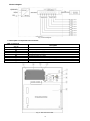
Features:
9 p 10/100 Mb/s ports
8 PoE ports (data transfer and power supply)
15,4W for each PoE port, supports devices complaint
with the IEEE802.3af standard
Supports auto-learning and auto-aging of MAC
addresses (1K size)
Recorder space of dimensions max 400x345x100mm
WxHxD
LED indication
Additional assembly elements
Metal enclosure – color white RAL 9003
warranty – 2 year from the production date
Example of use of the power supply Switch.
1. Technical description
1.1. General description.
The S98-CR is a complete kit to build the CCTV system based on IP cameras. The switch is placed in a metal enclosure
with recorder space.
Automatic detection of any devices powered in the PoE standard is enabled at the 1 – 8 ports of the switch. The UPLINK port is
used for connection of another network device. The LEDs at the front panel indicate the operation status (description in the table
below).
The PoE technology ensures a network connection and reduces installation costs by eliminating the need to supply a separate
power cable for each device. This method allows supplying other network devices, such as IP phone, wireless access point or
router.

2
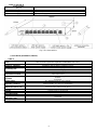
1.2 Block diagram.
Fig. 1. Block diagram.
1.3. Description of components and connectors.
Table 1. (see Fig.2)
Element no.
(Fig. 2)
Description
[1]
Switch
[2]
Switch mode power supply for the switch 48VDC/2,5A/120W
[3]
Potentiometer adjusting the output voltage of the power supply (46÷52V)
[4]
LED light – power supply operation indication
[5]
F 6,3A / 250V fuse socket
[6]
Mounting brackets for cables
[7]
Space for the 48VDC/2,5A/120W power supply of the recorder (desktop type)
[8]
Power Socket of the 230V AC recorder
[9]
Recorder space of dimensions max 400x345x100mm WxHxD
Fig. 2. The enclosure view.

3
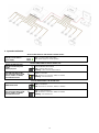
Table 2. (See Fig.3)
Component No.
(Fig. 3)
Description
[1]
8 x PoE port (1÷8)
[2]
1 x UPLINK port
[3]
48VDC power supply socket
Fig. 3 The view switch'a.
1.4. Technical parameters (Table 3.)
Table 3.
Ports
9 10/100Mb/s ports (8 x PoE + 1 x UPLINK)
with connection speed auto-negotiation and MDI/MDIX Auto Cross)
PoE power supply
IEEE 802.3af (1÷8 ports), 48VDC / 15,4W at each port
Protocols, Standards
IEEE802.3, 802.3u, 802.3x CSMA/CD, TCP/IP
Forwarding rate
10BASE-T: 14880pps/port
100BASE-TX: 148800pps/port
Bandwidth
1,6Gbps
Transmission method
Store-and-Forward
Optical indication of
operation
Switch power supply;
Link/Act;
PoE Status
Power supply
90 ÷ 264VAC 50÷60Hz / 2,5A 230VAC
Operating conditions
temperature -10°C ÷ 45°C,
relative humidity 5% - 90%, no condensation
Dimensions (W x H x D)
Switch: 190 x 28 x 115 [mm]
Enclosure: 540 x 440 x 110+14 [mm]
Enclosure
Steel plate, DC01 1,0mm color white RAL 9003
Closing
Cheese screw x 1 (at the front)
Notes
The enclosure does not adjoin the assembly surface so that cables can be led
Gross/Net weight
7,63/8,31kg
Protection class
EN 60950-1:2007
II (second)
Storage temperatur
-20°C ÷ 60°C
Declarations
CE, RoHS

4
2. Installation
2.1. Installation procedure
1. The unit should be mounted by a qualified installer, holding relevant permits and licenses (applicable and required
for a given country) for 230V/AC interference and low-voltage installations.
2. The unit should be mounted in confined spaces, in accordance with the 2nd environmental class, with normal
relative humidity (RH=90% maximum, without condensation) and temperature from -10°C to +45°C.
3. The switch shall work in a vertical position that guarantees sufficient convectional air-flow through ventilating holes
of the enclosure. The power supply load balance should be done before installation. During normal operation, the
total current drawn by the receivers cannot exceed I=2,5A. The device is designed for a continuous operation and
is not equipped with a power-switch. Therefore, an appropriate overload protection in the power supply circuit
should be provided. Moreover, the user should be informed how to disconnect the power supply unit from the
mains supply (usually by assigning an appropriate fuse in the fuse box). The electrical system shall be made in
accordance with applicable standards and regulations.
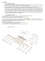
2.2. Installation procedure
1. Before installation, make sure that the voltage in the 230V power-supply circuit is cut off.
2. Mount the PSU in a selected location and connect the wires.
3. Connect the power cables (~230V) to the L-N terminals of the power supply.
4. Connect the ground wire to the terminal marked by the earth symbol PE (power supply module connector). Use a
three-core cable (with a yellow and green PE protection wire) to make the connection. Lead the cables to the appropriate
terminals of the connection board through the insulating bushing.
5. Connect the power (~230V).
6. Connect the camera wires to the RJ45 connectors (PoE connectors).
7. Check the optical indication of the switch operation.
8. After installing and checking proper working, the enclosure can be closed
Connection schemes.

5
3. Operation indication.
OPTICAL INDICATION OF THE SWITCH's POWER SUPPLY
GREEN LED LIGHT (Power)
Indication of the switch's
power supply
OFF – no power supply of the switch
ON – power supply on, normal operation
OPTICAL INDICATION AT THE PoE PORTS (1÷8)
DIODA LED ZIELONA (PoE)
Indication of the PoE power
supply
at the RJ45 ports
OFF- no power supply at the RJ45 port (the device is not connected or not compliant
with the IEEE802.3af standard)
ON – supply at the RJ45 port
Blinking – short-circuit or output overload
YELLOW LED LIGHT (LINK)
The connection status of LAN
devices, 10MB/s or 100Mb/s
and data transmission
OFF- no connection
ON - the device is connected ; 10Mb/s or 100Mb/s
Blinking – data transmission
OPTICAL INDICATION AT THE UPLINK PORT
GREEN LED LIGHT
OFF- no connection
ON – the device is connected ; 10Mb/s or 100Mb/s
YELLOW LED LIGHT (LINK)
The connection status of LAN
devices, 10MB/s or 100Mb/s
and data transmission
OFF- no data transmission
ON - the device is connected : 10Mb/s or 100Mb/s
Blinking – data transmission

6
WEEE LABEL
Waste electrical and electronic equipment must not be disposed of with normal household waste.
According to the European Union WEEE Directive, waste electrical and electronic equipment
should be disposed of separately from normal household waste.
GENERAL WARRANTY CONDITIONS
1. Pulsar (manufacturer) grants a two-year quality warranty for the equipment, starting from the production date.
2. The warranty includes free-of-charge repair or replacement with an appropriate equivalent (selected by the manufacturer) if the
malfunction is due to the manufacturer. It includes manufacturing or material defects, provided that such defects have been
reported within the warranty period (point.1).
3. The equipment subjected to warranty should be brought to the place of purchase or directly to the main office of the
manufacturer.
4. The warranty applies to complete equipment, accompanied by a properly filled warranty claim with a description of the defect.
5. Should the claim be accepted, the manufacturer is obliged to provide warranty repairs, at the earliest convenience, however not
later that within 14 days from the delivery to the service centre of the manufacturer.
6. The repair period mentioned in point 5 may be prolonged, if there are no technical possibilities to carry out the repairs, or if the
equipment has been conditionally accepted, due to the breaking warranty terms by the claimant.
7. All the services are carried out at the service centre of the manufacturer, exclusively.
8. The warranty does not cover the defects of the equipment, resulting from:
- reasons beyond the manufacturer's control,
- mechanical damage,
- improper storage and transport,
- use that violates the operation manual or equipment’s intended use
- fortuitous events, including lightning discharges, power failures, fire, flood, high temperatures and chemical agents,
- improper installation and configuration (failure to follow instruction).
9. The warranty is void in case of construction changes and repairs carried out by any unauthorized service center or in case of
damage or modifications to warranty stickers and serial numbers.
10. The liability of the manufacturer towards the buyer is limited to the value of the equipment determined according to the
wholesale prices suggested by the manufacturer on the day of purchase.
11. The manufacturer takes no responsibility for the defects that result from the damaging, malfunctioning or inability to operate
the equipment especially when resulting from failure to comply with the recommendations and requirements contained in the
manual.
Pulsar
Siedlec 150, 32-744 Łapczyca, Poland
Tel. (+48) 14-610-19-40, Fax. (+48) 14-610-19-50
e-mail: biuro@pulsar.pl, sales@pulsar.pl
http:// www.pulsar.pl, www.zasilacze.pl
-
 1
1
-
 2
2
-
 3
3
-
 4
4
-
 5
5
-
 6
6


Pulsar S98-CR - v1.0 Operating instructions
- Type
- Operating instructions
Pulsar S98-CR - v1.0 is a complete kit to build a CCTV system based on IP cameras. It is placed in a metal enclosure with recorder space.
Key features of the device:
- 9 10/100 Mb/s ports
- 8 PoE ports (data transfer and power supply)
- 15,4W for each PoE port, supports devices compliant with the IEEE802.3af standard
- Supports auto-learning and auto-aging of MAC addresses (1K size)
- Recorder space of dimensions max 400x345x100mm WxHxD
- LED indication
- Additional assembly elements
- Metal enclosure – color white RAL 9003
- Warranty – 2 years from the production date
Possible use cases:
Ask a question and I''ll find the answer in the document
Finding information in a document is now easier with AI
Related papers
-
Pulsar S98-CR - v1.1 Operating instructions
-
-
-
-
-
-
-
-
-