Page is loading ...

Metra. The World’s Best Kits.
®
MetraOnline.com © COPYRIGHT 2020 METRA ELECTRONICS CORPORATION REV. 7/16/20 INST99-8164
INSTALLATION INSTRUCTIONS
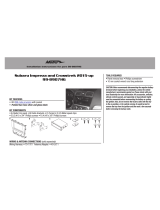
99-8164
Attention! Let the vehicle sit with the key
out of the ignition for a few minutes before
removing the factory radio. When testing the
aftermarket equipment, ensure that all factory
equipment is connected before cycling the
key to ignition.
• ISO DDIN radio provision
• ISO DIN radio provision with pocket
• Custom texture and painted tan or gray to match the factory appearance
• Touchscreen for retention of climate control functions
• Factory amplifier not retained with this product - an amplifier bypass
harness is included
• 99-8164T — Tan w/black trim, 99-8164G — Gray w/black trim
KIT FEATURES
KIT COMPONENTS
• A) Radio trim panel • B) Radio brackets • C) Pocket • D) Panel clips (3) • E) #8 x 3/8” Pan-head Philips screws (8)
• F) Wiring and interfacing (not shown)
TOOLS REQUIRED
• Panel removal tool • Phillips screwdriver
• 10mm Socket wrench
TABLE OF CONTENTS
Dash Disassembly ..................................................2
Kit Preparation .......................................................3
Kit Assembly ..........................................................4
Axxess Interface Installation .............................5-11
Final Assembly .......................................................9
WIRING & ANTENNA CONNECTIONS
Wiring Harness: Included with kit
Antenna Adapter:
Not needed
Lexus RX300 1999-2003
A B C D
E
Visit MetraOnline.com for more detailed information about the product and up-to-date vehicle
specific applications

386.257.1187
|
MetraOnline.com
2
DASH DISASSEMBLY
1. Unsnap and remove the shifter trim.
(Figure A)
2. Remove (4) 10mm bolts and remove the
radio assembly. (Figure B)
3. Depress side tabs to remove the factory
hazard button and passenger airbag
light from the factory radio assembly.
(Figure C)
4. Depress all four side tabs to remove
the factory vents from the factory radio
assembly. (Figure D)
Continue to Kit Preparation
(Figure B) (Figure D)
(Figure A) (Figure C)

REV. 7/16/2020 INST99-8164
3
KIT PREPARATION
1. Attach the (3) supplied panel clips to the
radio trim panel. (Figure A)
2. Snap the passenger airbag light and
hazard button into the radio trim panel
from the back. (Figure B)
3. Attach the factory vents to the radio
trim panel (Figure C)
Continue to Kit Assembly
(Figure A)
(Figure B) (Figure C)

386.257.1187
|
MetraOnline.com
4
KIT ASSEMBLY
ISO-DIN radio provision with pocket
1. Secure the pocket to the radio brackets
using the (4) #8 x 3/8” Phillips screws
supplied. (Figure A)
2. Attach the radio bracket/pocket
assembly to the radio using screws
supplied with the radio. (Figure B)
3. Attach the completed assembly to the
radio trim panel using the supplied (4)
#8 x 3/8” Phillips screws. (Figure C)
Continue to Axxess Interface Installation
ISO-DDIN radio provision
1. Secure the radio brackets to the radio
using screws supplied with the radio.
(Figure A)
2. Attach the completed assembly to the
radio trim panel using the supplied (4)
#8 x 3/8” Phillips screws. (Figure B)
Continue to Axxess Interface Installation
(Figure B)
(Figure C)
(Figure B)
(Figure A)
(Figure A)

REV. 7/16/2020 INST99-8164
5
AXXESS INTERFACE INSTALLATION
INTERFACE FEATURES
INTERFACE COMPONENTS
• Axxess interface (built into the touchscreen display)
• Bean Bus interface
• 8164 harness
• 8164 NAV harness
• 4-pin harness with yellow RCA jacks
• Factory amplifier not retained with this product – an amplifier bypass harness included
TOOLS REQUIRED
• Crimping tool and connectors, or solder gun, solder, and heat shrink • Tape
• Wire cutter • Zip ties
TABLE OF CONTENTS
Connections ............................................................................................................................... 6-8
Installation ....................................................................................................................................9
Programming ................................................................................................................................ 9
Touchscreen display operation ...............................................................................................10-11
• Provides accessory power (12-volt 10-amp)
• Retains R.A.P. (retained accessory power)
• Touchscreen for retention of climate control functions
• Micro “B” USB updatable
5

386.257.1187
|
MetraOnline.com
6
CONNECTIONS
From the LD-8164 harness to the aftermarket radio:
• Connect the Black wire to the ground wire.
• Connect the Yellow wire to the battery wire.
• Connect Red wire to the accessory wire.
• Tape off and disregard the following (4) wires, they will not be used in this application:
Gray, Gray/Black, White, White/Black
*For speaker wire connections, refer to the AX-AB-LX4 amplifier bypass harness Instructions
The Yellow/Black ‘Bean BUS’ wire must be connected properly for this interface to function:
Locate the 13 pin connector in the vehicle.
The following connections will have to be made.
•
‘Bean BUS (Yellow/Black)’
– to the factory Yellow/Black wire.
• Radio’s Illumination wire – to the factory Green wire (if desired)
Illumination (+)
Green wire on factory side
Bean BUS (+)
Yellow/Black wire on factory side
Front of 13 pin connector
Wire side of 13 pin connector
Illumination (+)
Bean BUS
6

REV. 7/16/2020 INST99-8164
7
CONNECTIONS (CONT.)
Use the LD-8164-NAV harness for vehicles with Factory Navigation
From the LD-8164-NAV harness to the aftermarket radio:
• Connect Black to the ground wire
• Connect Yellow to the battery/ memory wire.
• Connect Red to the accessory wire.
• Connect Orange to the Illumination wire.
• Connect Blue to the radio’s Antenna/Remote wire.
• Tape off and disregard the following wires: White, White/Black, Gray, and Gray/Black.*
*For speaker wire connections, refer to the AX-AB-LX4 amplifier bypass harness Instructions.
The Yellow/Black ‘Bean BUS’ wire must be connected properly for this interface to function:
Locate the gray 14 pin connector in the vehicle.
The following connections will have to be made.
• Connect the Yellow/Black wire labelled ‘Bean BUS’ to the Yellow/Black wire on the factory
connector.
A military/lineman splice is recommended to ensure a good connection.*
*Always insulate all connections.
The following connections are only necessary if installing a Multimedia / Navigation radio &
desire the additional outputs:
• Connect the radios
Vehicle Speed Sense
wire to the factory Violet/White wire.
• Connect the radios
Park
wire to the factory Red/White wire.
Gray (Control Panel)
White (Multi Display)
Yellow/Black – ‘Bean BUS’ wire
- Connect to labeled wire on LD-8164
Violet/White – Vehicle Speed Sense
Red/White – Parking Brake
7

386.257.1187
|
MetraOnline.com
8
4-pin harness with yellow RCA jacks:
• Backup camera harness (4-pin harness with yellow RCA jacks):
• There are two different methods for connecting an aftermarket camera. To the touchscreen
or to the aftermarket radio (see radio manual)
• If connecting a backup camera to the touchscreen display is desired, connect the Yellow RCA
jack labeled “Rearview camera”, to the aftermarket camera.
• IF this method is chosen, see camera options in the Configuration Settings section.
• Disregard the Yellow RCA jack labeled “AUX video”, it will not be used in this application.
Amplifier bypass:
Use the included amplifier bypass to connect to the speakers. Take note that there are multiple
speakers with varying impedance. An external amplifier and crossovers are recommended.
AX-AB-LX4:
From the 10p Connector:
Green Rear Left Door Speaker (+)
Green/Black Rear Left Door Speaker (-)
Gray Front Right Speaker / Tweeter (+)
Gray/Black Front Right Speaker / Tweeter (-)
White Front Left Speaker / Tweeter (+)
White/Black Front Left Speaker / Tweeter (-)
From the 6p Connector:
Green/White Subwoofer 1 (+) (If applicable)
White/Red Subwoofer 1 (-) (If applicable)
Purple Rear Right Door Speaker (+)
Purple/Black Rear Right Door Speaker (-)
Brown/Yellow Subwoofer (+)
Brown/Blue Subwoofer (-)
CONNECTIONS (CONT.)
8

REV. 7/16/2020 INST99-8164
99
INSTALLING THE INTERFACE
FINAL ASSEMBLY
PROGRAMMING
• Open the drivers door and keep open during the process.
• Cycle the ignition to on.
• Connect the harnessing to the vehicle.
• Wait until the radio powers on and the touchscreen displays “SWC configured”.
• Cycle the ignition off and back on.
• Test all functions.
It is highly advisable to read the following steps beforehand, to ensure a clear understanding of
what is to be expected. The following steps must be done in the order that they are numbered.
With the vehicle completely off:
Touchscreen display
1. Connect the 8164 harness to the wiring harnesses in the vehicle. Then insert the 8164
harness into port “A” in the touchscreen display.
2. If adding an aftermarket back-up camera to the touchscreen. Connect the 4-pin
harness with yellow RCA jacks into port “C” in the touchscreen display.
3. Disregard port “E” and “B” and “D”, it will not be used in this application.
4. Port “F” is an update port for future firmware upgrades.
5. Locate the factory antenna connector in the dash and complete all necessary
connections to the radio. Metra recommends using the proper mating adapter
from Metra.
A
F
D
C
E
B
1. Secure the completed assembly into the dash using the factory hardware and reassemble
the dash in reverse order of disassembly.

386.257.1187
|
MetraOnline.com
10
TOUCHSCREEN DISPLAY OPERATION
• This is the HVAC control screen which will be displayed on the touchscreen display. This is
considered the main screen.
• The upper right tab with the gear icon will take you to the Configuration Settings screen.
• The climate controls will function in the same manner that they did with the factory
climate controls.
HVAC control screen Configuration Settings screen
Backlight
• For controlling the color of the buttons and back-light intensity.
Backup Camera
• Enable/disable the backup camera image to the touchscreen display. Disabled by default.
System Configuration
• About - Information regarding the software in the kit.
• Vehicle Config – Factory features.
• Reset Vehicle Type - To reset the kit to default settings.
10

REV. 7/16/2020 INST99-8164
11
TOUCHSCREEN DISPLAY OPERATION (CONT.)
Touchscreen calibration:
• Press and hold the upper two soft buttons on either side of the touchscreen for 10 seconds.
• A screen will pop up asking for you to press the target in the screen.
• After pressing the target with your finger, the calibration process will be complete, and the
screen will disappear.
11

KNOWLEDGE IS POWER
Enhance your installation and fabrication skills by
enrolling in the most recognized and respected
mobile electronics school in our industry.
Log onto www.installerinstitute.com or call
800-354-6782 for more information and take steps
toward a better tomorrow.
®
Metra recommends MECP
certified technicians
Metra. The World’s Best Kits.
®
MetraOnline.com © COPYRIGHT 2020 METRA ELECTRONICS CORPORATION REV. 7/16/20 INST99-8164
INSTALLATION INSTRUCTIONS
99-8164
Having difficulties? We’re here to help.
Contact our Tech Support line at:
386-257-1187
Or via email at:
techsupport@metra-autosound.com
Tech Support Hours (Eastern Standard Time)
Monday - Friday: 9:00 AM - 7:00 PM
Saturday: 10:00 AM - 7:00 PM
Sunday: 10:00 AM - 4:00 PM
/