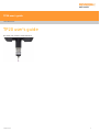
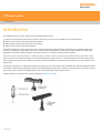
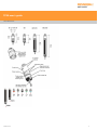
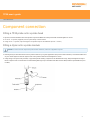
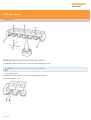
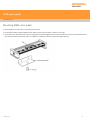
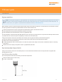
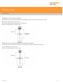
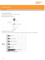
Renishaw TP20 is a versatile touch-trigger probe system with automatic stylus changing, designed to enhance the capabilities of coordinate measuring machines (CMMs). It provides high accuracy and repeatability in various measurement applications, enabling efficient and reliable part inspection. Key features of the TP20 include:
-
Automatic stylus changing: The TP20 allows for quick and easy stylus changes without the need for requalification, increasing productivity and reducing downtime.
-
High accuracy and repeatability: With its precise kinematic design and advanced sensing technology, the TP20 delivers accurate and repeatable measurements, ensuring reliable and consistent results.


-
 1
1
-
 2
2
-
 3
3
-
 4
4
-
 5
5
-
 6
6
-
 7
7
-
 8
8
-
 9
9
-
 10
10
-
 11
11
-
 12
12
-
 13
13
-
 14
14
-
 15
15
-
 16
16
-
 17
17
-
 18
18
-
 19
19
-
 20
20
-
 21
21
-
 22
22
-
 23
23
-
 24
24
-
 25
25
-
 26
26
-
 27
27
-
 28
28
-
 29
29
-
 30
30
-
 31
31
-
 32
32
-
 33
33
-
 34
34
-
 35
35
-
 36
36
-
 37
37
-
 38
38
-
 39
39


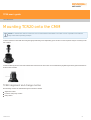
Renishaw TP20 is a versatile touch-trigger probe system with automatic stylus changing, designed to enhance the capabilities of coordinate measuring machines (CMMs). It provides high accuracy and repeatability in various measurement applications, enabling efficient and reliable part inspection. Key features of the TP20 include:
-
Automatic stylus changing: The TP20 allows for quick and easy stylus changes without the need for requalification, increasing productivity and reducing downtime.
-
High accuracy and repeatability: With its precise kinematic design and advanced sensing technology, the TP20 delivers accurate and repeatable measurements, ensuring reliable and consistent results.
Ask a question and I''ll find the answer in the document
Finding information in a document is now easier with AI
Related papers
-
Renishaw TP20 User guide
-
-
-
Renishaw RTP20 User guide
-
-
-
-
Renishaw TP200 User guide
-
-
Other documents
-
König CS2STYLA100 Datasheet
-
Lumens MS-EM1 Installation guide
-
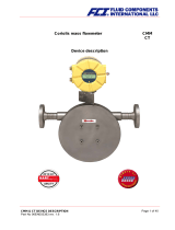 Fluid Components International CMM User guide
-
Conceptronic CSTYLUSREG Datasheet
-
Zeiss MCR20 Owner's manual
-
Sealey PH20.v4 Operating instructions
-
Toshiba TEC EM1-33043A User manual
-
 T2 MD-EM1 Owner's manual
-
NEC V850/SC2 User manual
-
Puretec WH1 Whole House Water Filtration Systems User guide

