Page is loading ...


www.lifebreath.com 1
Pre-Installation Notes
Note
• Due to ongoing research and product development, specifications, ratings, and dimensions are subject
to change without notice. Refer to www.lifebreath.com for the latest product information.
Attention
• Do not apply electrical power to the unit until after the completion of the installation (including
installation of low voltage control wiring).
• Ensure the installation and wiring is in accordance with CEC, NEC, and local electrical codes.
• Plug the unit into a standard designated (120 VAC) electrical outlet with ground.
• The use of an extension cord with this unit is not recommended. If the installation requires further
wiring, have a licensed electrician make all of the electrical connections. The recommended circuit is a
separate 15 A/120 V circuit.
Caution
• Before installation, careful consideration must be given to how this system will operate if connected to
any other piece of mechanical equipment, i.e. a forced air furnace or air handler, operating at a higher
static. After installation, the compatibility of the two pieces of equipment must be confirmed, by
measuring the airflows of the HRV, by using the balancing procedure found in this manual. Never install
a ventilator in a situation where its normal operation, lack of operation or partial failure may result in the
back drafting or improper functioning of vented combustion equipment
• Unit must be installed level to ensure proper condensate drainage. Due to the broad range of installation
and operational conditions, consider the possibility of condensation forming on either the unit or
connecting ducting. Objects below the installation may be exposed to condensate.
• Do not install control wiring alongside electrical wire.
• Pool room air/surfaces must have a heating appliance which does not include the pool water as its
source. The pool room and water must be continuously operated at its original design as any deviation
from this could greatly effect the operation of the unit. The pool unit must be fully commissioned after
installation which includes confirming proper operation of the control, normal operation of the unit, and
drainage through the pans without unintentional leakage.
Warning
• Disconnect the power from the unit before cleaning or servicing.
• To prevent electrical shock, it is extremely important to confirm the polarity of the power line that is
switched by the safety (disconnect) switch. The hot line (black) is the proper line for switching. Use
either a voltmeter or test lamp to confirm the absence of a voltage between the disconnect switch and
ground (on the cabinet) while the door is open. This procedure must be followed, as dwellings are
occasionally wired improperly. Always ensure the proper grounding of the unit.
• Improper installation, adjustment, alteration, service or maintenance can cause property damage,
personal injury or loss of life. Installation and service must be performed by a qualified installer or
service agency.

www.lifebreath.com 2
Table of Contents
1 Location Notes ................................................................................................................................................................ 3
2 The Duct Work System .................................................................................................................................................... 4
3 Sample Duct Layout 1 ..................................................................................................................................................... 5
4 Sample Duct Layout 2 ..................................................................................................................................................... 6
5 Dimensional Drawings .................................................................................................................................................... 7
6 Stale Air Return and Fresh Air Supply System ................................................................................................................ 8
7 Weatherhoods and Grilles .............................................................................................................................................. 9
8 Drain Connections ......................................................................................................................................................... 10
9 Electrical Connections ................................................................................................................................................... 11
10 Modes of Operation for the Pool HRV ...................................................................................................................... 12
11 Calculating the Ventilation Rate for the Pool Room ................................................................................................. 13
12 Table 1 – Evaporation Rates...................................................................................................................................... 14
13 Table 2 – Flow Rate Factors ...................................................................................................................................... 15
14 Make Up Heat ........................................................................................................................................................... 16
15 Defrost Time Adjustment .......................................................................................................................................... 16
16 Reversing the Supply and Defrost Air Ports .............................................................................................................. 17
17 Function and Controls ............................................................................................................................................... 18
18 Main Wall Control ..................................................................................................................................................... 19
19 Dehumidistat ............................................................................................................................................................. 20
20 Balancing the Airflows .............................................................................................................................................. 21
21 Service and Maintenance .......................................................................................................................................... 23
22 Reverse Installation of the HRV ................................................................................................................................ 25
23 Troubleshooting ........................................................................................................................................................ 27
24 Wiring Diagrams (700/1200POOL) ............................................................................................................................ 29
25 Warranty ................................................................................................................................................................... 30
Warranty Information
Refer to the last page in this manual for complete Warranty information.

www.lifebreath.com 3
1 LOCATION NOTES
The HRV must be in a heated space where the surrounding air temperature does not fall below 60°F
(16°C). The unit must be mounted level (horizontal) to obtain proper drainage of water from the heat
exchange element and drip pans. The warranty will be void if these conditions are not met. Typically,
the HRV is positioned close to an outside wall or the roof to simplify the connections and keep the
length of insulated ducting required for the fresh air intake to a minimum.
A minimum clearance of 30 inches (76 cm) in front of the HRV is recommended to service the heat
exchanger cores and the filters. The HRV may be mounted on an equipment platform providing the
drain hoses are clear and there is sufficient space to open the doors for servicing.
Saddle Installation
(1) Threaded rod (not supplied)
(2) Vibration isolators (not supplied)
Hang unit with suspended rods and “U” channel members
Curb Mounted Installation
(3) Curb—Wood or Metal (not supplied)
(4) Vibration isolators (not supplied)
Mount unit on wooden or metal curb assembly. Unit must be
raised an adequate height for installation and slope of drain
lines. May be anchored to floor, leaving space for drain
connections.
Suspended Installation
(5) PVC support straps (not supplied)
Suspend the unit using polyester reinforced PVC support
straps.
Warning
• Flexible duct connectors should be installed between the ERV and the galvanized ductwork.

www.lifebreath.com 4
2 THE DUCT WORK SYSTEM
A properly designed ducting system will allow the HRV to operate at its maximum efficiency. (Air flow
will be restricted by undersized ducting, use of too many elbows, tees, bends, etc.). Always try to
keep duct runs as short and straight as possible.
Proper duct design & duct sizing will:
• Minimize air flow requirements.
• Ensure a comfortable environment by using reheat if required.
• Optimize humidity control, including eliminating condensation on windows by blanketing the
windows with airflow.
Refer to Sample Duct Layout 1 and 2 for typical duct system designs.
All joints must be airtight, sealed and impervious to moisture. See Dimensional Drawings for each
unit for exact duct sizes and location.
To minimize pressure drop and noise, galvanized metal ducts, properly sized, are recommended.
Keep ducting as short as possible and use a minimum of elbows and tees. Connecting sections and
shorter runs may be flexible ducting one size larger than the metal equivalent. Use flexible duct
connectors at the HRV to avoid noise transmission.
All duct joints must be secured with screws, rivets or duct sealant and sealed with aluminum duct
tape to prevent leakage.
Attention
• Fully insulated ducting with an integral vapour barrier must be used on all runs passing through unheated
areas in order to avoid condensation problems and energy losses from the air systems.

www.lifebreath.com 5
3 SAMPLE DUCT LAYOUT 1
System Installation:
It is necessary to design and size the duct distribution system for both the supply and the exhaust air streams.

www.lifebreath.com 6
4 SAMPLE DUCT LAYOUT 2
System Installation:
It is necessary to design and size the duct distribution system for both the supply and the exhaust air streams.

www.lifebreath.com 7
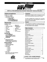
5 DIMENSIONAL DRAWINGS
700POOL Dimensions:
1200POOL Dimensions:

www.lifebreath.com 8
6 STALE AIR RETURN AND FRESH AIR SUPPLY SYSTEM
Stale Air Return System:
Many commercial activities produce air contaminants in the form of dusts, fumes,
mists, vapors and gases. Contaminants should be controlled at the source, so they
are not dispersed through the building or allowed to increase to toxic
concentration levels. The ventilator allows for economical operation of the HVAC
system while effectively removing contaminants from the space. In designing the
exhaust portion of the system, the exhaust grilles are situated to remove the
contaminants while not allowing them to enter the breathing zone of the
occupants.
The stale air return system is used to draw air from the points in the building where the worst air quality problems occur.
Balancing dampers and/or adjustable grilles are recommended on all return air lines which are used during installation to
help balance the “draw” from different areas of the building.
For contaminants lighter than air, grilles should be located high on the wall. If contaminants are heavier than air, a lower
placement of the grilles will be required. Information on a contaminants specific gravity and toxicity should be available
from chemical data sheets.
Alternately, the stale air may be drawn directly from the return air duct. When this system is used, the air handler’s
blower must constantly operate. The exhaust take-off connection must be at least 3 ft (1 m) from a directly connected
ERV supply duct if both are connected to the same duct run. Note and compensate for the static pressure of the air
handlers return system if the static pressure of the return in the air handler exceeds .1 to .15” W.C.
A damper located just prior to the HRV is required to balance the stale air exhausted with the fresh air supply entering
the building.
Return air suction points should be located on the opposite side of the room from the fresh air inlet. The inlets may be in
the ceiling or high on the walls and fitted with inlet grilles.
Fresh Air Supply System:
The fresh air supply ductwork from the HRV may be directly connected to the
furnace return air duct when a dedicated forced air system is present for the
pool room. Check the air flow balance of the HRV with the air handler blower
both “ON” and “OFF” to determine that it does not imbalance the HRV more than
10%. Also, it is advisable to include a short length of flex duct or other non-
metallic connector in this hard ducted line in order to keep the HRV acoustically
isolated and separately grounded (electrically) from the air handler. This will
avoid a possible shock hazard to service people if a short to ground develops in
one of the devices.
When installing an HRV, the designer and installer should be aware of local codes that may require smoke detectors
and/or firestats in the HVAC or HRV ductwork. Because an HRV is designed to bring fresh air into the building, structures
may require supply voltage interrupt when smoke or flame sensors are triggered, or when a central fire alarm system is
activated.
Supply air grilles may be ceiling or high wall mounted. Avoid locating incoming fresh air grilles that could cause a direct
draft on the occupants as the incoming air may be below room temperature. A reheat duct heater can be installed to
improve occupant comfort.

www.lifebreath.com 9
7 WEATHERHOODS AND GRILLES
Outside Weatherhoods:
The weatherhoods must have built-in “bird” screen with 1/4 in (6.35 mm) minimum mesh to prevent birds and
rodents from entering into the ductwork. Do not use smaller mesh as it will be very susceptible to plugging
up. Gravity dampers at the vents must not be used as they will restrict air flow and often “seize up”. The
preferred location of the outside weatherhoods is:
• no less than 10 ft. (3 m) apart from each other
• at least 18 in (46 cm) above snow line or ground level
• away from sources of contaminants, such as automobile exhaust fumes, gas meters, garbage cans,
containers, etc.
• not exposed to prevailing winds
• The outside perimeter of the weatherhood must be caulked to prevent leakage into the building.
• The design and size of the weatherhoods or louvers chosen by the installer must allow for adequate
free area. Water and debris penetration of the system is minimized when the airflow does not exceed
1000 FPM (5.08 m/s) free area velocity.
Ducting from the Weatherhoods:
• Galvanized sheet metal ducting with enough cross section with an integral single piece vapor barrier
should be used to connect the ERV to the weatherhoods.
• A minimum R value of insulation should be equal to 4 (RSI 0.75)
• A good bead of high quality caulking (preferably acoustical sealant) and taping with a high quality
aluminum foil tape is recommended to seal the duct to both the ERV and the weatherhood.
Adjustable Grilles:
The use of balancing dampers or adjustable grilles as supply air diffusers and air exhaust covers are
recommended. TECHGRILLES™ are round, efficient, sound absorbing devices available in 4”, 5”, 6” and 8”
(100, 125, 150, and 200 mm) models.
Part# 99-EAG4 4” diameter Techgrille
Part# 99-EAG5 5” diameter Techgrille
Part# 99-EAG6 6” diameter Techgrille
Part# 99-EAG8 8” diameter Techgrille
Attention
• All ducting must meet UL Class 1 requirements
• Design and install the fresh air intake in an area where the hoods will gather the freshest air.

www.lifebreath.com 10
8 DRAIN CONNECTIONS
The HRV cabinet has pre-punched holes for the drain. The HRV may produce some condensation
during a defrost cycle. This water should flow into a nearby drain or be taken away by a condensate
pump.
Figure Callouts:
(1) Drain Spout
(2) Drain Pan
(3) Lock Nut
(4) Tee Connector
(5) Drain Hose
(6) Drain Line
(7) Zip Tie
Installation Steps:
1. Install the drain spout through the hole in the drain pan.
2. Hand tighten the lock nut which holds the drain spout in place.
3. Construct a P-trap using the plastic tee connector.
4. Cut two lengths of 1/2 in. drain hose (not included) and connect the other ends to the two drain
spouts.
5. Position the tee connector to point upward and connect the drain line. Use a zip tie to secure the drain
line to one of the 1/2 in. drain hoses.
6. Tape or fasten base to avoid any kinks.
7. Pour a cup of water into the drain pan of the HRV after the drain connection is complete. This creates a
water seal which will prevent odours from being drawn up the hose and into the fresh air supply of the
HRV.
Caution
• The HRV and all condensate lines must be installed in a space where the temperature is maintained
above the freezing point.
• Drain trap and tubing must be below bottom of door with 1/4" per foot downwards slope away
from unit.
• A secondary drain pan may be required to protect from condensate leakage.

www.lifebreath.com 11
9 ELECTRICAL CONNECTIONS
It is recommended that a licensed electrician make all electrical connections. It is very important that
the unit be properly grounded. The circuit must be sized to handle the Full Load Amperage (FLA)
indicated on the name tag for the circuit.
.
Unit
Maximum AMP Rating
HIGH
MED.
LOW
700POOL
4.5
-
-
1200POOL
9.4
6.0
4.5
Warning
• Verify the polarity of the power coming into the unit with a test lamp or multimeter. Connect the
multimeter or test lamp probe to the wire being tested and the other probe to ground. The black
line should be “live”. If the white line is “live” the polarity is reversed and must be corrected. If both
lines are live, the voltage is not 120VAC. The black open line from the unit should be connected to
the live line and the white open line should be connected to the neutral line. Some unit have a safety
disconnect rocker switch located just outside of the electrical control box area. The switch
disconnects the live line. Verify that it is working properly with a multimeter or test lamp. Always
ensure the HRV is properly grounded before and after testing.
Caution
• The HRV is designed to operate with ducting. When first starting the HRV, measure the amp draw to
each motor at each speed to ensure it is operating at or below the max rating.

www.lifebreath.com 12
10 MODES OF OPERATION FOR THE POOL HRV
Ventilation Mode
In ventilation mode, both motors are
running, and air is being exchanged with
the outside through the supply and exhaust
ducts.
Recirculation Mode
In recirculation mode the supply motor
continues to run, and a damper moves to
block off air entering from outside, drawing
air instead from the conditioned space. The
exhaust to outside motor is OFF when in
recirculation mode.
Defrost Mode
All pool HRVs have an electronically
controlled damper defrost mechanism. The
defrost timer is activated when outside
temperatures drop below 27°F (-3°C). A
motor driven damper door mechanism
opens the “pool and defrost air port” and
closes off the “supply air from outside”
port. This defrost cycle operates for about
3 minutes and then the damper reverts to
its previous “run time” position.

www.lifebreath.com 13
11 CALCULATING THE VENTILATION RATE FOR THE POOL ROOM
Example:
Pool surface area
16’ x 32’ (512 sq ft)
*Indoor design air temperature
83°F
Pool water temperature
81°F
*Relative humidity
50%
*Outdoor design air temperature
15°F
*Always use design temperatures and outdoor air temperatures. Outdoor design temperatures
are published by organizations such as ASHRAE. Do not use day to day temperatures for this
calculation.
1. From Table 1, select the appropriate evaporation rate based on the room air temperature, water
temperature, and relative humidity:
Evaporation Rate = 0.052
2. From Table 2, select the corresponding flow rate factor depending on the indoor air temperature,
outdoor temperature, and room relative humidity:
Flow Rate Factor = 21.70
3. Multiply the values obtained from Step 1 and Step 2 to obtain the minimum CFM required per square
foot of pool surface area:
Evaporation Rate x Flow Rate Factor = CFM / square foot of water surface area
0.052 x 21.70 = 1.12
4. Multiply the value in Step 3 by the area of the pool:
Area of Pool x Value for Step 3 = CFM
512 x 1.12 = 573
Attention
• Spas/Hot Tubs must be considered when calculating the ventilation rate for a pool room. This ventilation rate
is calculated by adding 10 cfm / ft
2
of Spa/Hot Tub surface area. For example, a 25 ft
2
Spa/Hot Tub will add
250 cfm to your pool calculation.

www.lifebreath.com 14
12 TABLE 1 – EVAPORATION RATES
Indoor
Air
Temp.
(°F)
Indoor Relative Humidity (%)
40
50
60
40
50
60
40
50
60
Evaporation Rate lb / (sq. ft-hr.)
68
0.069
0.063
0.056
0.079
0.073
0.066
0.090
0.084
0.077
70
0.068
0.060
0.053
0.078
0.070
0.063
0.088
0.081
0.074
72
0.065
0.058
0.050
0.075
0.068
0.060
0.086
0.079
0.071
74
0.063
0.055
0.047
0.073
0.065
0.057
0.084
0.076
0.068
76
0.061
0.052
0.043
0.071
0.062
0.053
0.082
0.073
0.064
78
0.059
0.049
0.039
0.069
0.059
0.049
0.080
0.070
0.060
80
0.056
0.046
0.035
0.066
0.056
0.045
0.077
0.067
0.056
82
0.053
0.042
0.031
0.063
0.052
0.041
0.074
0.063
0.052
84
0.050
0.039
0.027
0.060
0.049
0.037
0.071
0.060
0.048
86
0.047
0.065
0.022
0.057
0.045
0.032
0.068
0.056
0.043
88
0.044
0.031
0.017
0.054
0.041
0.027
0.065
0.052
0.038
Water
Temp.
(°F)
78
81
84
Indoor
Air
Temp.
(°F)
Indoor Relative Humidity (%)
40
50
60
40
50
60
40
50
60
Evaporation Rate lb / (sq. ft-hr.)
68
0.102
0.095
0.089
0.115
0.108
0.102
0.129
0.122
0.116
70
0.100
0.093
0.086
0.113
0.106
0.099
0.127
0.120
0.113
72
0.098
0.090
0.083
0.111
0.103
0.096
0.125
0.117
0.110
74
0.096
0.088
0.079
0.109
0.101
0.092
0.123
0.115
0.106
76
0.094
0.085
0.076
0.107
0.098
0.089
0.121
0.112
0.103
78
0.091
0.082
0.072
0.104
0.095
0.085
0.118
0.109
0.099
80
0.089
0.079
0.068
0.102
0.091
0.081
0.116
0.105
0.095
82
0.086
0.075
0.064
0.099
0.088
0.077
0.113
0.102
0.091
84
0.083
0.071
0.060
0.096
0.084
0.073
0.110
0.098
0.087
86
0.080
0.068
0.055
0.093
0.080
0.068
0.107
0.094
0.082
88
0.077
0.063
0.050
0.090
0.076
0.063
0.104
0.090
0.077
Water
Temp.
(°F)
87
90
93

www.lifebreath.com 15
13 TABLE 2 – FLOW RATE FACTORS
Outside Air
Temp. (°F)
Indoor Relative Humidity (%)
40
50
60
40
50
60
40
50
60
Flow Rate Factor (cfa-hr./lb.)
-30
39.70
31.50
26.10
35.70
28.30
23.40
32.10
25.50
21.10
-25
40.20
31.80
26.20
36.10
28.50
23.60
32.40
25.70
21.20
-20
40.80
32.10
26.50
36.50
28.80
23.80
32.80
25.90
21.40
-15
41.60
32.60
26.80
37.20
29.20
24.00
33.30
26.20
21.60
-10
42.60
33.20
27.20
38.00
29.70
24.40
34.00
26.60
21.90
-5
43.90
34.10
27.80
39.00
30.40
24.80
34.80
27.10
22.20
0
45.70
35.10
28.50
40.40
31.20
25.40
25.90
27.80
22.70
5
48.10
36.50
29.40
42.30
32.30
26.10
37.40
28.70
23.20
10
51.50
38.40
30.60
44.90
33.80
27.00
39.40
29.80
24.00
15
56.20
41.00
32.20
48.50
35.80
28.30
42.10
31.40
25.00
20
63.40
44.70
34.50
53.70
38.50
30.00
46.00
33.50
26.30
25
74.90
50.10
37.60
61.70
42.50
32.40
51.80
36.40
28.10
30
95.90
58.70
42.30
75.30
48.50
35.80
61.00
40.80
30.60
35
112.78
69.62
46.60
84.08
54.75
38.60
66.18
44.71
32.53
40
129.66
80.53
50.90
92.86
61.00
41.40
71.36
48.63
34.46
45
146.54
91.45
55.20
101.64
67.25
44.20
76.54
52.55
36.40
50
163.42
102.37
59.50
110.42
73.50
47.00
81.72
56.47
38.30
55
180.30
113.28
63.80
119.20
79.75
49.80
86.90
60.38
40.26
60
243.30
124.20
68.10
127.98
86.00
52.60
92.08
64.30
42.20
Indoor Air
Temp. (°F)
68
71
74
Outside Air
Temp. (°F)
Indoor Relative Humidity (%)
40
50
60
40
50
60
40
50
60
Flow Rate Factor (cfa-hr./lb.)
-30
29.00
23.00
19.00
26.10
20.70
17.20
23.60
18.70
15.50
-25
29.20
23.10
19.10
26.30
20.90
17.20
23.80
18.80
15.60
-20
29.50
23.30
19.20
26.60
21.00
17.40
24.00
19.00
15.70
-15
29.90
23.60
19.40
26.90
21.20
17.50
24.20
19.10
15.80
-10
30.40
23.90
19.60
27.30
21.50
17.70
24.60
19.30
15.90
-5
31.10
24.30
19.90
27.90
21.80
17.90
25.00
19.60
16.10
0
32.00
24.80
20.30
28.60
22.20
18.20
25.60
20.00
16.30
5
33.20
25.50
20.70
29.50
22.80
18.60
26.30
20.40
16.60
10
34.70
26.40
21.30
30.70
23.50
19.00
27.30
21.00
17.00
15
36.80
27.60
22.10
32.40
24.50
19.60
28.60
21.70
17.50
20
39.70
29.30
23.10
34.60
25.70
20.40
30.30
22.70
19.10
25
44.00
31.50
24.50
37.80
27.40
21.50
32.70
24.10
19.00
30
50.50
34.70
26.40
42.50
29.80
23.00
36.20
25.90
20.10
35
57.46
37.32
27.77
46.85
31.63
23.99
39.10
27.20
20.83
40
64.43
39.94
29.13
51.20
33.47
24.97
42.00
28.50
21.57
45
71.39
42.56
30.50
55.50
35.30
25.95
44.90
29.80
22.30
50
78.36
45.18
31.87
59.90
37.13
26.93
47.80
31.10
23.03
55
85.33
47.80
33.23
64.25
39.96
27.92
50.70
32.40
23.76
60
92.30
50.40
34.60
68.60
40.80
28.90
53.60
33.70
24.50
Indoor Air
Temp. (°F)
77
80
83

www.lifebreath.com 16
14 MAKE UP HEAT
Make up heat is usually necessary for pool HRVs that are installed as a Fully Dedicated Duct System. An
electric in line duct heater or hydronic coil will be necessary to bring the Supply Air to Inside back up to room
temperature. Contact your distributor for duct heater sizing and pricing information.
15 DEFROST TIME ADJUSTMENT
Damper Defrost
Damper defrost HRV's have an electronically controlled damper defrost mechanism. If the outside temperature
drops below 27°F (-3°C), the defrost timer is activated. A motor driven damper door mechanism opens the
defrost port and at the same time closes off the supply air from outside. After the defrost period, the damper
operates in the opposite direction to close off the defrost port and reopen the fresh air at the supply port.
Defrost cycle repeats until the temperature again rises above 27° F (-3°C).
• If the indoor air temperature is too low, the defrost time may need to be increased.
• The unit must be mounted level (horizontal) to obtain proper drainage of water from the heat
exchange cores and drip pans. The warranty will be void if these conditions are not met.
Defrost Time Adjustment
DIP switch #8 (located on the Aircom circuit board) will adjust the defrost time.
Factory Setting (DIP Switch 8 OFF)
The HRV enters defrost mode when outdoor
temperatures drop below 27°F (-3°C). The factory
defrost cycle is 4 minutes defrost with a 30 minute
run time.
Increased Defrost Time (DIP Switch 8 ON)
Cooler climates may require a more aggressive
defrost cycle. Positioning DIP switch 8 to ON will
initiate a 4 minute defrost with a 20 minute run
time.
Caution
• Do not change any of the other DIP switch settings.

www.lifebreath.com 17
16 REVERSING THE SUPPLY AND DEFROST AIR PORTS
Sometimes installation is easier if the "Fresh Air from Outside" is ducted from the upper left side port (Defrost
Air) instead of the top port. Changing the functionality of these two ports is easily accomplished by switching
the red and yellow defrost motor wires at the circuit board: switch T37 and T39 on the circuit board.
Switch T37 (red wire) and T39 (yellow wire) on the circuit board if you wish to reverse the "Supply Air from
Outside" and "Defrost Air" ports. This illustration shows the factory configuration.

www.lifebreath.com 18
17 FUNCTION AND CONTROLS
Basic Functions
Pool units normally operate in recirculation mode at the selected speed. When the dehumidistat sense
moisture above the setpoint, the RHV will switch to ventilate mode and operate at the same speed. Once the
dehumidistat is satisfied, the HRV reverts to recirculation mode.
Setup
Speed control is obtained by powering 24V to one of the designated speed taps. Select appropriate operational
speed by installing the jumper wire between one of the designated speed taps on the P1 terminals on the
Aircom circuit board. A jumper wire is factory installed in the low speed position.
Aircom Circuit Board
Optional 3 Speed Control (99-500)
See Page 19 for installation on circuit board.
Optional Dehumidistat (99-DH01)
See Page 20 for installation on circuit board.
Speed
Jumper Wire Placement
High
R
W
Medium
R
Y
Low (factory setting)
R
G

www.lifebreath.com 19
18 MAIN WALL CONTROL
3-Speed Control (99-500) Operation:
(1) High Speed Fan
(2) Medium Speed Fan
(3) Low Speed Fan
Press the applicable Fan Speed button to set the fan speed. Press the
applicable OFF button in order to turn the Fan Speed control off.
3-Speed Control (99-500) Installation:
Connect the wires from the control to the R, W, Y, and G terminals on the circuit board as shown:
Attention
• Use 4 wire; 20 gauge wire (mimium)
• When used in conjunction with the 99-BC02, the BC02 control must be ON for the 99-500 control
to operate. The 99-BC02 will override the 99-500 control when the Dehumidistat is operating or the
control is set to HIGH speed
/