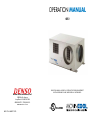
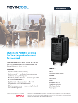
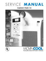
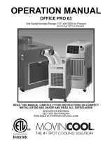
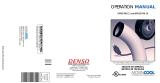
Movincool CM12 is a powerful air conditioning unit designed for commercial use. It features a 12,000 BTU cooling capacity, making it ideal for cooling medium-sized rooms. The CM12 is easy to install and operate, with a variety of features to ensure efficient and reliable cooling. These features include a built-in thermostat, a condensate pump, and a variety of safety features. Whether you're looking to cool a server room, a retail store, or a small office, the Movincool CM12 is a great choice.
Movincool CM12 is a powerful air conditioning unit designed for commercial use. It features a 12,000 BTU cooling capacity, making it ideal for cooling medium-sized rooms. The CM12 is easy to install and operate, with a variety of features to ensure efficient and reliable cooling. These features include a built-in thermostat, a condensate pump, and a variety of safety features. Whether you're looking to cool a server room, a retail store, or a small office, the Movincool CM12 is a great choice.


-
 1
1
-
 2
2
-
 3
3
-
 4
4
-
 5
5
-
 6
6
-
 7
7
-
 8
8
-
 9
9
-
 10
10
-
 11
11
-
 12
12
-
 13
13
-
 14
14
-
 15
15
-
 16
16
-
 17
17
-
 18
18
-
 19
19
-
 20
20
-
 21
21


Movincool CM12 is a powerful air conditioning unit designed for commercial use. It features a 12,000 BTU cooling capacity, making it ideal for cooling medium-sized rooms. The CM12 is easy to install and operate, with a variety of features to ensure efficient and reliable cooling. These features include a built-in thermostat, a condensate pump, and a variety of safety features. Whether you're looking to cool a server room, a retail store, or a small office, the Movincool CM12 is a great choice.
Ask a question and I''ll find the answer in the document
Finding information in a document is now easier with AI
Related papers
-
Movincool CM12 Operating instructions
-
Movincool OFFICEPRO12 Product Catalog
-
-
 Movincool CPD12 Installation guide
-
 Movincool CM25 Specification
-
 Movincool CPD12 Installation guide
-
 Movincool CPD12 Installation guide
-
 Movincool OFFICEPRO63 Operations Manual
-
 Movincool OP24 Owner's manual
-
 Movincool OFFICE PRO 12 Operating instructions


Other documents
-
Denso Air Conditioner OFFICE PRO 18 User manual
-
-
-
-
-
Airwell HRW 042 Installation and Maintenance Manual
-
-
Advent AC135HP Operating instructions
-
 Prime-Line U 9573 Operating instructions
