Page is loading ...

Vintage POW! V3
Colorsound’s awesome
Power Boost and Overdriver
Contents of this document are ©2023 Pedal Parts Ltd.
No reproduction permitted without the express written
permission of Pedal Parts Ltd. All rights reserved.

Before you dig in, ensure you download
and read the General Build Guide.
It contains all the information you need
for a successful outcome.
General
Build
Guide
Your first stop
for build info
Contents of this document are ©2023 Pedal Parts Ltd.
No reproduction permitted without the express written
permission of Pedal Parts Ltd. All rights reserved.

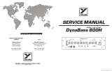
Full board
schematic
This is the full circuit laid out
on the PCB. It has the parts
and connections for both
variations (Power Boost and
Overdriver). The following
pages show only those used
in each version.

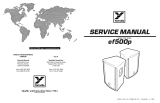
Schematic / BOM - Overdriver
R1 120K
R2 6K8
R3 150K
R4 Jumper
R5 12K
R5B Empty
R6 1K8
R7 4K7
R8 39K
R9 5K6
R10 4K7
R11 33K
R12 150K
R13 1K8
R14 470R
R15 470R
C1 220n
C2 22u elec
C3 22u elec
C4 220p
C5 10u elec
C6 10n
C7 10n
C8 100n
C9 100n
C10 10u elec*
C11 220n
C12 22u elec
C13 100u elec
C14 Empty
C15 Empty
C16 Empty
D1 1N5817
D2-3 Empty
IC1 Empty
Q1-3 BC109
DRIVE 5KC
TREB 100KB
BASS 100KB
VOL 100KA
*Reverse the orientation of C10.
Place a jumper across the pads marked J1.
Transistors should be placed as shown >>>

*Reverse the orientation of C10.
If you wish to power this at 18V from your 9V
supply, include the charge pump parts listed in
green. If you’re using an 18V supply just leave
those out and jumper the pads marked J1.
Transistors should be placed as shown >>>
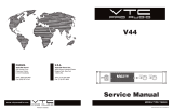
Schematic / BOM - Power Boost
R1 120K
R2 4K7
R3 150K
R4 470R
R5 Empty
R5B 12K
R6 1K8
R7 4K7
R8 39K
R9 5K6
R10 4K7
R11 33K
R12 180K
R13 3K9
R14 1K
R15 1K2
C1 220n
C2 22u elec
C3 22u elec
C4 220p
C5 10u elec
C6 10n
C7 10n
C8 100n
C9 100n
C10 22u elec*
C11 220n
C12 10u elec
C13 100u elec
C14 10u elec
C15 10u elec
C16 10u elec
D1 1N5817
D2-3 1N4148
IC1 7660SEPA
Q1-3 BC169C or BC184L
DRIVE 5KC
TREB 100KB
BASS 100KB
VOL 100KA

PCB layout ©2023 Pedal Parts Ltd.
Snap the small metal tag off the pots so
they can be mounted flush in the box.
You should solder all other board-mounted
components before you solder the pots.
Once they’re in place you’ll have no access to
much of the board.

This template is a rough guide only. You should ensure correct marking of your
enclosure before drilling. You use this template at your own risk.
Pedal Parts Ltd can accept no responsibility for incorrect drilling of enclosures.
FuzzDog.co.uk
32mm
27mm
Drill sizes:
Pots 7mm
Jacks 10mm
Footswitch 12mm
DC Socket 12mm
Toggle switches 6mm
Rotary switches 10mm
Drilling template
Hammond 1590B - 60 x 111 x 31mm
Drill sizes listed are minimum.
It’s a good idea to add 1mm to anything
mounted on the PCB that’ll poke
through the front of the enclosure.
/